WO2020121684A1 - Appareil de congélation - Google Patents
Appareil de congélation Download PDFInfo
- Publication number
- WO2020121684A1 WO2020121684A1 PCT/JP2019/043028 JP2019043028W WO2020121684A1 WO 2020121684 A1 WO2020121684 A1 WO 2020121684A1 JP 2019043028 W JP2019043028 W JP 2019043028W WO 2020121684 A1 WO2020121684 A1 WO 2020121684A1
- Authority
- WO
- WIPO (PCT)
- Prior art keywords
- opening
- compressor
- plate portion
- unit base
- machine room
- Prior art date
- Legal status (The legal status is an assumption and is not a legal conclusion. Google has not performed a legal analysis and makes no representation as to the accuracy of the status listed.)
- Ceased
Links
Images



Classifications
-
- F—MECHANICAL ENGINEERING; LIGHTING; HEATING; WEAPONS; BLASTING
- F24—HEATING; RANGES; VENTILATING
- F24F—AIR-CONDITIONING; AIR-HUMIDIFICATION; VENTILATION; USE OF AIR CURRENTS FOR SCREENING
- F24F1/00—Room units for air-conditioning, e.g. separate or self-contained units or units receiving primary air from a central station
- F24F1/06—Separate outdoor units, e.g. outdoor unit to be linked to a separate room comprising a compressor and a heat exchanger
- F24F1/08—Compressors specially adapted for separate outdoor units
- F24F1/10—Arrangement or mounting thereof
-
- F—MECHANICAL ENGINEERING; LIGHTING; HEATING; WEAPONS; BLASTING
- F25—REFRIGERATION OR COOLING; COMBINED HEATING AND REFRIGERATION SYSTEMS; HEAT PUMP SYSTEMS; MANUFACTURE OR STORAGE OF ICE; LIQUEFACTION SOLIDIFICATION OF GASES
- F25B—REFRIGERATION MACHINES, PLANTS OR SYSTEMS; COMBINED HEATING AND REFRIGERATION SYSTEMS; HEAT PUMP SYSTEMS
- F25B1/00—Compression machines, plants or systems with non-reversible cycle
-
- F—MECHANICAL ENGINEERING; LIGHTING; HEATING; WEAPONS; BLASTING
- F25—REFRIGERATION OR COOLING; COMBINED HEATING AND REFRIGERATION SYSTEMS; HEAT PUMP SYSTEMS; MANUFACTURE OR STORAGE OF ICE; LIQUEFACTION SOLIDIFICATION OF GASES
- F25D—REFRIGERATORS; COLD ROOMS; ICE-BOXES; COOLING OR FREEZING APPARATUS NOT OTHERWISE PROVIDED FOR
- F25D19/00—Arrangement or mounting of refrigeration units with respect to devices or objects to be refrigerated, e.g. infrared detectors
Definitions
- the present invention relates to a refrigeration system.
- a refrigeration system including a refrigerant circuit including a compressor, a condenser, a throttle device, an evaporator and the like has been conventionally used.
- a mixture of the refrigerant and a lubricating oil mainly used for lubricating the sliding portion of the compressor circulates.
- the capacity and efficiency of such refrigeration equipment depend on various parameters.
- One of the parameters is the refrigerant temperature at the compressor outlet. If the pressure of the refrigerant at the compressor outlet reaches a predetermined pressure, the lower the refrigerant temperature at the compressor outlet, the better.
- the conventional refrigeration system had room for improvement regarding the refrigerant temperature at the compressor outlet.
- the present invention has been made in view of such a situation, and an object of the present invention is to provide a refrigeration apparatus capable of reducing the refrigerant temperature at the compressor outlet.
- a refrigerating apparatus includes a compressor that constitutes a refrigerant circuit, and a first plate portion that is arranged below the compressor, and the first plate portion is the first plate portion. Has a first opening that connects the upper region and the lower region and overlaps the orthogonal projection of the compressor on the first plate portion.
- the front view of the refrigerating device concerning one embodiment.
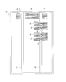
- FIG. The bottom view of a stand leg.
- FIG. 1 is a front view of a refrigerating apparatus 1 according to the present invention.
- the refrigeration system 1 includes a door 2 for opening and closing a cooling chamber (not shown), a handle 3 used for opening and closing the door 2, a hinge 4 for connecting the door 2 to a main body (not shown) for opening and closing, and an operating section 5 operated by a user.
- the refrigerating apparatus 1 has a machine room below the freezing room.
- the machine room is surrounded by a machine room housing 6.
- a ventilation part 7 for taking in air into the machine room is provided on the front side of the machine room housing 6, that is, on the side where the door 2 is attached.
- the refrigeration system 1 includes legs 8 at the lower part of the machine room housing 6, that is, at the bottom of the refrigeration system 1. Since the legs 8 are provided, a space is secured below the machine room.
- FIG. 2 is a perspective view of the inside of the machine room.
- the bottom of the machine room is covered with a base leg 10.
- a leg 8 is provided below the base leg 10.
- the base leg 10 is provided with a plurality of openings (hereinafter, the openings provided in the base leg 10 are referred to as “second openings”), the details of which will be described later.
- a plurality of mesh panels such as the first mesh panel 11 are attached to the base leg 10 so as to cover the second openings.
- the base leg 10 is also referred to as a “second plate portion”.
- the unit base 20 is placed on the base leg 10.
- the unit base 20 is also referred to as a “first plate portion”.
- the unit base 20 is provided with two first openings 23 and 24. The two first openings 23, 24 will be described in detail later.
- the refrigeration system 1 has a first refrigerant circuit and a second refrigerant circuit that are independent of each other.
- Numeral 31 in FIG. 2 is a condenser shared by the first refrigerant circuit and the second refrigerant circuit.
- 32 is a fan that generates an air flow for cooling the condenser 31.
- 33 is a first compressor that constitutes a first refrigerant circuit.
- Reference numeral 34 is a second compressor that constitutes a second refrigerant circuit.
- the pipes that connect the devices shown in FIG. 2 and the cables that supply power or control signals to these devices are not shown.
- the expansion device forming the first refrigerant circuit and the expansion device forming the second refrigerant circuit are not shown.
- the evaporator forming the first refrigerant circuit and the evaporator forming the second refrigerant circuit are arranged outside the machine room.
- FIG. 3 is a perspective view of the base leg 10. Further, FIG. 4 is a bottom view of the base leg 10.
- a rail 12 is attached to the upper surface of the base leg 10.
- the unit base 20 can slide on the rail 12. Therefore, it is easy to remove the unit base 20 to the outside of the machine room. Therefore, the equipment in the machine room can be taken out together with the unit base 20, and the maintenance of the equipment can be easily performed.
- a second mesh panel 13 and a third mesh panel 14 are attached to the base leg 10.
- the first mesh panel 11 covers the second opening 15, the second opening 16 and the second opening 17 provided in the base leg 10.
- the second mesh panel 13 covers the second opening 18 provided in the base leg 10.
- the third mesh panel 14 covers the second opening 19 provided in the base leg 10.
- the first mesh panel 11, the second mesh panel 13, and the third mesh panel 14 all have fine through holes through which air can pass.
- a reinforcement member 41 and a reinforcement member 42 are attached to the lower surface of the base leg 10.
- the reinforcing member 42 located below the second opening 18 and the second opening 19 is provided with an auxiliary opening 43 penetrating in the vertical direction.
- the auxiliary opening 43 is vertically aligned with the second opening 18 or the second opening 19. It is needless to say that either one or both of the reinforcing member 41 and the reinforcing member 42 may be arranged above the base leg 10 as necessary. In that case, the reinforcing member 41 and/or the reinforcing member 42 arranged on the upper side of the base leg 10 may be used instead of the rail 12.
- FIG. 5 is a plan view of the periphery of the first compressor 33 and the second compressor 34.
- the first compressor 33 has four bases 33a, and is installed on the unit base 20 via the bases 33a.
- the second compressor 34 has four bases 34a, and is installed on the unit base 20 via the bases 34a. Needless to say, the number of bases 33a and the number of bases 34a are not limited to four.
- the first compressor 33 and the second compressor 34 have a substantially elliptical shape in plan view, although not particularly limited thereto.
- the first opening 23 is provided in the unit base 20 so that the entire area thereof overlaps the orthogonal projection of the first compressor 33 onto the unit base 20. In other words, the first opening 23 is completely surrounded by the orthographic contour of the first compressor 33 on the unit base 20. Alternatively, it can be said that the first opening 23 is arranged inside a virtual circle that passes through the centers of the four bases 33a.
- the first opening 24 is provided in the unit base 20 so that the entire area thereof overlaps the orthogonal projection of the second compressor 34 onto the unit base 20. In other words, the first opening 24 is completely surrounded by the orthographic contour of the second compressor 34 on the unit base 20. Alternatively, it can be said that the first opening 24 is arranged inside a virtual circle that passes through the centers of the four base portions 34a.
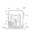
- FIG. 6 is a schematic vertical sectional view of the first compressor 33 or the second compressor 34. Since the second compressor 34 has the same structure as the first compressor 33, only the first compressor 33 will be described below.
- the first compressor 33 has a casing 301.
- a motor 302 is arranged inside the casing 301.
- a piston 303 is connected to the motor 302 via a crank mechanism.
- the piston 303 is arranged so as to be able to reciprocate inside the cylinder 304.
- An inlet 305 serving as a refrigerant inlet to the first compressor 33 and an outlet 306 serving as a refrigerant outlet from the first compressor 33 are attached to a part of the casing 301.
- a terminal box 307 to which a cable for supplying electric power to the motor 302 and a cable for transmitting a signal for controlling the first compressor 33 are connected is attached to the outside of the casing 301.
- the inside of the casing 301 is filled with lubricating oil for reducing the friction of the members such as the piston 303 that move inside the casing 301.
- the bottom of the casing 301 constitutes a lubricating oil sump in which the lubricating oil is stored.
- the refrigeration system 1 configured as described above operates as follows.
- the operation of the first compressor 33 and the second compressor 34 is started, and the refrigerant begins to circulate in the first refrigerant circuit and the second refrigerant circuit.
- the refrigerant circulates as follows.
- first refrigerant circuit or the first compressor 33 may be described, but those descriptions also apply to the second refrigerant circuit or the second compressor 34.
- the refrigerant that has been compressed by the first compressor 33 and has increased in temperature is supplied to the condenser 31.
- the refrigerant supplied to the condenser 31 exchanges heat with the air supplied by the fan 32, is cooled, and is condensed.
- the rotation of the fan 32 draws cooling air from the outside of the refrigeration system 1 through the ventilation part 7.
- the refrigerant condensed in the condenser 31 flows into a throttling device (not shown) to expand, and then flows into an evaporator (not shown) to be evaporated.
- a throttling device not shown
- an evaporator not shown
- the refrigerant cools the cooling chamber of the refrigeration system 1. After that, the refrigerant again flows into the first compressor 33 and is compressed.
- the first compressor 33 becomes hot.
- the refrigerant discharged from the first compressor 33 also becomes hot.
- the cause is the heat generated by the compression of the refrigerant and the heat generated by the operation of machines such as the motor 302 and the piston 303.
- the first compressor 33 is cooled by the mechanism described below, and thus the refrigerant compressed therein is also cooled.
- the airflow generated by the rotation of the fan 32 collides with the outer surface of the first compressor 33. Subsequently, the airflow passes through the first opening 23 and moves from the upper region of the unit base 20 to the lower region. That is, in the present embodiment, it is possible to increase the amount of airflow that contacts the lower region of the first compressor 33.
- the bottom of the casing 301 of the first compressor 33 constitutes a lubricating oil sump in which this lubricating oil is stored. Therefore, by increasing the amount of the air flow that contacts the lower region of the first compressor 33, the heat exchange amount between the air flow and the lubricating oil via the casing 301 can be increased.
- the lubricating oil also plays a role of contacting the refrigerant in the casing 301 and performing heat exchange.
- the heat exchange efficiency between the refrigerant in the first compressor 33 and the air flowing outside the first compressor 33 can be improved, and the first compressor 33 can be improved.
- the temperature of the refrigerant discharged from the can be reduced.
- the first opening 23 also contributes to eliminating the radiation heat radiated from below the casing 301 being absorbed or reflected by the unit base 20. That is, even if the air flow is not supplied from the fan 32, the cooling efficiency of the first compressor 33 is improved only by the existence of the first opening 23.
- the entire area of the first opening 23 overlaps with the orthogonal projection of the first compressor 33 on the unit base 20. Therefore, the airflow colliding with the first compressor 33 can be more efficiently guided to the lower region of the unit base 20, and the cooling efficiency of the first compressor 33 can be increased. ..
- the air flow that collides with the first compressor 33 will fall below the unit base 20. It is possible to guide to the side. Therefore, the entire area of the first opening 23 does not necessarily have to overlap with the orthogonal projection of the first compressor 33 on the unit base 20.
- the unit base 20 is necessary for disposing the first opening 23, the first opening 24, and a member (for example, the condenser 31) for configuring the refrigeration apparatus 1.
- a member for example, the condenser 31 for configuring the refrigeration apparatus 1.
- No opening is provided other than the opening. Therefore, the airflow that has moved from the upper side to the lower side of the unit base 20 via the first opening 23 or the first opening 24 does not return to the upper side of the unit base 20 again. That is, the refrigeration system 1 is configured so that the air flow does not circulate between the upper region and the lower region of the unit base 20. Therefore, it is prevented in advance that the air that has cooled the first compressor 33 and has become high in temperature comes into contact with the first compressor 33 again and reduces the cooling efficiency of the first compressor 33. ..
- the unit base 20 may be provided with openings other than the openings required for arranging the first opening 23, the first opening 24, and members for configuring the refrigerating apparatus 1. In this case, for example, by arranging a rectifying member on the lower side of the unit base 20 so that the airflow that has moved downward through the first opening 23 does not go to the opening, the upper side of the unit base 20 is increased. It is possible to prevent air circulation between the region and the lower region.
- the second leg 15, the second leg 16, the second leg 17, the second leg 18 and the second leg 19 are formed on the base leg 10 that constitutes the bottom of the machine room. It is provided. Therefore, the airflow that has flowed into the lower side of the unit base 20 through the first opening 23 or the first opening 24 does not stay between the unit base 20 and the base leg 10 and does not reach the bottom of the base leg 10. Can flow to the side. Therefore, the air flow from the upper side to the lower side of the unit base 20 can be made smooth via the first opening 23 or the first opening 24.
- the second opening 18 is vertically aligned with the first opening 23, and the second opening 19 is vertically aligned with the first opening 24. Therefore, the air that has flowed over the base leg 10 through the first opening 23 or the first opening 24 can be flowed more smoothly below the base leg 10. That is, by arranging the second opening 18 and the second opening 19 so as to be vertically aligned with the first opening 23 and the first opening 24, the first compressor 33 and the second compressor 34 are arranged. The cooling efficiency of can be further improved.
- the reinforcing member 42 located below the second opening 18 and the second opening 19 is provided with an auxiliary opening 43.
- the position where the auxiliary opening 43 is provided is a position that is vertically aligned with the second opening 18 and the second opening 19, that is, a position that is aligned with the first opening 23 and the first opening 24. Therefore, the flow of air that has flowed into the lower side of the base leg 10 through the second opening 18 or the second opening 19 is smoothly flowed below the reinforcing member 42 without being blocked by the reinforcing member 42. be able to.
- the unit base 20 is not provided with a reinforcing member, but a reinforcing member similar to the reinforcing member 41 and the reinforcing member 42 provided on the base leg 10 may be provided.
- a reinforcing member similar to the reinforcing member 41 and the reinforcing member 42 provided on the base leg 10 may be provided.
- the rail 12 When the rail 12 is located below the first opening 23 or the first opening 24, it goes without saying that the rail 12 may be provided with an opening for flowing air below the base leg 10.
- the base leg 10 configures the bottom of the machine room, but the base leg 10 may be omitted and the unit base 20 may configure the bottom of the machine room.
- a member such as a mesh panel, which allows air to freely flow but does not allow foreign matter to pass, is arranged in the first opening 23 and the first opening 24. Is preferred.
- the first opening 23, the first opening 24, the second opening 15, the second opening 16, the second opening 17, the second opening 18, the second opening 19, and the auxiliary opening 43 are The function of discharging the refrigerant leaking inside the refrigeration system 1 to the outside is also fulfilled.
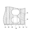
- the unit base 20 is configured by one plate-shaped member, but as illustrated in FIG. 7, the unit base 20 (that is, the first plate portion) has a plurality of plate members. It may be composed of the plate member 25. In this case, the first opening 26 can be formed by a gap between the plate members 25. In addition, 27 in FIG. 7 is a wall of the machine room. That is, the first plate portion may be composed of a plurality of plate members, and the first opening may be composed of a gap between the plate members. Similarly, the second plate portion may be composed of a plurality of plate members, and the second opening may be composed of a gap between the plate members.
- the machine room is arranged below the freezing room, but it goes without saying that the machine room may be arranged at another position.
- a machine room may be arranged beside the freezing room.
- the machine room may be divided into a plurality of, for example, two small machine rooms.
- the two machine rooms may be composed of a first small machine room and a second small machine room arranged above the first small machine room.
- the second opening and the first opening are formed in the base and the unit base arranged below the compressor arranged in the first small machine room, the first small machine is formed.
- the compressor arranged in the chamber can be cooled efficiently.
- the first opening is formed in the plate member, for example, the unit base, which is arranged below the compressor arranged in the second small machine room and above the first small machine room.
- the compressor arranged in the second machine room can be cooled efficiently.
- the first member may be attached to the plate member below the compressor arranged in the second small machine room and above the first small machine room. Needless to say, it is not necessary to form the opening.
- the present invention is preferably used as a refrigeration system.
Landscapes
- Engineering & Computer Science (AREA)
- Mechanical Engineering (AREA)
- General Engineering & Computer Science (AREA)
- Chemical & Material Sciences (AREA)
- Combustion & Propulsion (AREA)
- Physics & Mathematics (AREA)
- Thermal Sciences (AREA)
- Devices That Are Associated With Refrigeration Equipment (AREA)
Abstract
Cet appareil de congélation comprend un compresseur constituant un circuit de fluide frigorigène, et un premier élément de plaque disposé sous le compresseur. Le premier élément de plaque a une première ouverture à travers laquelle une région supérieure et une région inférieure du premier élément de plaque sont reliées, la première ouverture chevauchant une projection orthogonale du compresseur sur le premier élément de plaque.
Priority Applications (2)
| Application Number | Priority Date | Filing Date | Title |
|---|---|---|---|
| JP2020559808A JP7157824B2 (ja) | 2018-12-12 | 2019-11-01 | 冷凍装置 |
| JP2022131786A JP2022159557A (ja) | 2018-12-12 | 2022-08-22 | 冷凍装置 |
Applications Claiming Priority (2)
| Application Number | Priority Date | Filing Date | Title |
|---|---|---|---|
| JP2018232328 | 2018-12-12 | ||
| JP2018-232328 | 2018-12-12 |
Publications (1)
| Publication Number | Publication Date |
|---|---|
| WO2020121684A1 true WO2020121684A1 (fr) | 2020-06-18 |
Family
ID=71076306
Family Applications (1)
| Application Number | Title | Priority Date | Filing Date |
|---|---|---|---|
| PCT/JP2019/043028 Ceased WO2020121684A1 (fr) | 2018-12-12 | 2019-11-01 | Appareil de congélation |
Country Status (2)
| Country | Link |
|---|---|
| JP (2) | JP7157824B2 (fr) |
| WO (1) | WO2020121684A1 (fr) |
Citations (8)
| Publication number | Priority date | Publication date | Assignee | Title |
|---|---|---|---|---|
| JPS59178577U (ja) * | 1983-05-18 | 1984-11-29 | 株式会社日立製作所 | 冷蔵庫の箱体構造 |
| JPH03271583A (ja) * | 1990-03-20 | 1991-12-03 | Hitachi Ltd | スクロール圧縮機及びそれを用いたヘリウム液化用冷凍装置 |
| JPH09243234A (ja) * | 1996-03-05 | 1997-09-19 | Hoshizaki Electric Co Ltd | 冷却貯蔵庫における除霜排水蒸発装置 |
| JPH1130464A (ja) * | 1997-07-10 | 1999-02-02 | Hoshizaki Electric Co Ltd | 機械室の部品配置構造 |
| JP2005042953A (ja) * | 2003-07-24 | 2005-02-17 | Hoshizaki Electric Co Ltd | 冷却貯蔵庫 |
| JP2007101018A (ja) * | 2005-09-30 | 2007-04-19 | Sanyo Electric Co Ltd | 冷凍機ユニットにおける圧縮機の冷却構造 |
| JP2009002352A (ja) * | 2008-08-22 | 2009-01-08 | Daikin Ind Ltd | 圧縮機 |
| JP2017015343A (ja) * | 2015-07-03 | 2017-01-19 | 日立アプライアンス株式会社 | 冷蔵庫 |
Family Cites Families (6)
| Publication number | Priority date | Publication date | Assignee | Title |
|---|---|---|---|---|
| JPS5944531A (ja) * | 1982-09-03 | 1984-03-13 | Sanyo Electric Co Ltd | 一体型空気調和機 |
| JPS60176079U (ja) * | 1984-05-02 | 1985-11-21 | ダイキン工業株式会社 | 冷凍ユニツト |
| JPH07103638A (ja) * | 1993-10-07 | 1995-04-18 | Matsushita Refrig Co Ltd | 冷蔵庫 |
| JP3615345B2 (ja) * | 1997-02-19 | 2005-02-02 | 三洋電機株式会社 | 断熱貯蔵庫 |
| JP4189302B2 (ja) * | 2003-11-20 | 2008-12-03 | ホシザキ電機株式会社 | 冷却貯蔵庫 |
| JP2011021798A (ja) * | 2009-07-15 | 2011-02-03 | Panasonic Corp | 保冷米びつ装置 |
-
2019
- 2019-11-01 WO PCT/JP2019/043028 patent/WO2020121684A1/fr not_active Ceased
- 2019-11-01 JP JP2020559808A patent/JP7157824B2/ja active Active
-
2022
- 2022-08-22 JP JP2022131786A patent/JP2022159557A/ja active Pending
Patent Citations (8)
| Publication number | Priority date | Publication date | Assignee | Title |
|---|---|---|---|---|
| JPS59178577U (ja) * | 1983-05-18 | 1984-11-29 | 株式会社日立製作所 | 冷蔵庫の箱体構造 |
| JPH03271583A (ja) * | 1990-03-20 | 1991-12-03 | Hitachi Ltd | スクロール圧縮機及びそれを用いたヘリウム液化用冷凍装置 |
| JPH09243234A (ja) * | 1996-03-05 | 1997-09-19 | Hoshizaki Electric Co Ltd | 冷却貯蔵庫における除霜排水蒸発装置 |
| JPH1130464A (ja) * | 1997-07-10 | 1999-02-02 | Hoshizaki Electric Co Ltd | 機械室の部品配置構造 |
| JP2005042953A (ja) * | 2003-07-24 | 2005-02-17 | Hoshizaki Electric Co Ltd | 冷却貯蔵庫 |
| JP2007101018A (ja) * | 2005-09-30 | 2007-04-19 | Sanyo Electric Co Ltd | 冷凍機ユニットにおける圧縮機の冷却構造 |
| JP2009002352A (ja) * | 2008-08-22 | 2009-01-08 | Daikin Ind Ltd | 圧縮機 |
| JP2017015343A (ja) * | 2015-07-03 | 2017-01-19 | 日立アプライアンス株式会社 | 冷蔵庫 |
Also Published As
| Publication number | Publication date |
|---|---|
| JPWO2020121684A1 (ja) | 2021-10-21 |
| JP2022159557A (ja) | 2022-10-17 |
| JP7157824B2 (ja) | 2022-10-20 |
Similar Documents
| Publication | Publication Date | Title |
|---|---|---|
| KR102170317B1 (ko) | 공기조화기의 실외기 | |
| EP3745059B1 (fr) | Réfrigérateur incorporé | |
| US10816225B2 (en) | Movable air conditioner | |
| JP4940095B2 (ja) | 電子機器冷却システム | |
| EP3385626B1 (fr) | Machine extérieure | |
| JP5017088B2 (ja) | 電子機器冷却装置 | |
| WO2013046724A1 (fr) | Unité extérieure et dispositif de réfrigération | |
| WO2013046725A1 (fr) | Unité extérieure et dispositif de réfrigération | |
| US12072139B2 (en) | Refrigerator | |
| US9353968B2 (en) | Heat source unit of refrigerating apparatus | |
| KR102218078B1 (ko) | 이동형 공기조화기 | |
| JP7157824B2 (ja) | 冷凍装置 | |
| US20210389021A1 (en) | Air conditioner | |
| JP2009135287A (ja) | 電子機器冷却装置 | |
| JP2009134522A (ja) | 電子機器冷却システム | |
| KR20050008334A (ko) | 전기 냉동/냉장 쇼케이스 | |
| US20250020340A1 (en) | Outdoor unit of air conditioner | |
| JP2009134532A (ja) | 電子機器冷却装置 | |
| JP2001324174A (ja) | 冷凍機ユニット | |
| KR20250009307A (ko) | 공기조화기의 실외기 | |
| JP7058514B2 (ja) | 空気調和装置 | |
| KR20250040437A (ko) | 공기조화기의 실외기 | |
| MX2010008142A (es) | Sistema integrado de circulacion de aire aplicado a refrigeradores. | |
| KR20170001974A (ko) | 전기 전자장비 냉각 시스템 | |
| KR20050087385A (ko) | 공기조화기의 실외기 시스템 |
Legal Events
| Date | Code | Title | Description |
|---|---|---|---|
| 121 | Ep: the epo has been informed by wipo that ep was designated in this application |
Ref document number: 19894424 Country of ref document: EP Kind code of ref document: A1 |
|
| ENP | Entry into the national phase |
Ref document number: 2020559808 Country of ref document: JP Kind code of ref document: A |
|
| NENP | Non-entry into the national phase |
Ref country code: DE |
|
| 122 | Ep: pct application non-entry in european phase |
Ref document number: 19894424 Country of ref document: EP Kind code of ref document: A1 |