WO2020121684A1 - 冷凍装置 - Google Patents
冷凍装置 Download PDFInfo
- Publication number
- WO2020121684A1 WO2020121684A1 PCT/JP2019/043028 JP2019043028W WO2020121684A1 WO 2020121684 A1 WO2020121684 A1 WO 2020121684A1 JP 2019043028 W JP2019043028 W JP 2019043028W WO 2020121684 A1 WO2020121684 A1 WO 2020121684A1
- Authority
- WO
- WIPO (PCT)
- Prior art keywords
- opening
- compressor
- plate portion
- unit base
- machine room
- Prior art date
- Legal status (The legal status is an assumption and is not a legal conclusion. Google has not performed a legal analysis and makes no representation as to the accuracy of the status listed.)
- Ceased
Links
Images



Classifications
-
- F—MECHANICAL ENGINEERING; LIGHTING; HEATING; WEAPONS; BLASTING
- F24—HEATING; RANGES; VENTILATING
- F24F—AIR-CONDITIONING; AIR-HUMIDIFICATION; VENTILATION; USE OF AIR CURRENTS FOR SCREENING
- F24F1/00—Room units for air-conditioning, e.g. separate or self-contained units or units receiving primary air from a central station
- F24F1/06—Separate outdoor units, e.g. outdoor unit to be linked to a separate room comprising a compressor and a heat exchanger
- F24F1/08—Compressors specially adapted for separate outdoor units
- F24F1/10—Arrangement or mounting thereof
-
- F—MECHANICAL ENGINEERING; LIGHTING; HEATING; WEAPONS; BLASTING
- F25—REFRIGERATION OR COOLING; COMBINED HEATING AND REFRIGERATION SYSTEMS; HEAT PUMP SYSTEMS; MANUFACTURE OR STORAGE OF ICE; LIQUEFACTION SOLIDIFICATION OF GASES
- F25B—REFRIGERATION MACHINES, PLANTS OR SYSTEMS; COMBINED HEATING AND REFRIGERATION SYSTEMS; HEAT PUMP SYSTEMS
- F25B1/00—Compression machines, plants or systems with non-reversible cycle
-
- F—MECHANICAL ENGINEERING; LIGHTING; HEATING; WEAPONS; BLASTING
- F25—REFRIGERATION OR COOLING; COMBINED HEATING AND REFRIGERATION SYSTEMS; HEAT PUMP SYSTEMS; MANUFACTURE OR STORAGE OF ICE; LIQUEFACTION SOLIDIFICATION OF GASES
- F25D—REFRIGERATORS; COLD ROOMS; ICE-BOXES; COOLING OR FREEZING APPARATUS NOT OTHERWISE PROVIDED FOR
- F25D19/00—Arrangement or mounting of refrigeration units with respect to devices or objects to be refrigerated, e.g. infrared detectors
Definitions
- the present invention relates to a refrigeration system.
- a refrigeration system including a refrigerant circuit including a compressor, a condenser, a throttle device, an evaporator and the like has been conventionally used.
- a mixture of the refrigerant and a lubricating oil mainly used for lubricating the sliding portion of the compressor circulates.
- the capacity and efficiency of such refrigeration equipment depend on various parameters.
- One of the parameters is the refrigerant temperature at the compressor outlet. If the pressure of the refrigerant at the compressor outlet reaches a predetermined pressure, the lower the refrigerant temperature at the compressor outlet, the better.
- the conventional refrigeration system had room for improvement regarding the refrigerant temperature at the compressor outlet.
- the present invention has been made in view of such a situation, and an object of the present invention is to provide a refrigeration apparatus capable of reducing the refrigerant temperature at the compressor outlet.
- a refrigerating apparatus includes a compressor that constitutes a refrigerant circuit, and a first plate portion that is arranged below the compressor, and the first plate portion is the first plate portion. Has a first opening that connects the upper region and the lower region and overlaps the orthogonal projection of the compressor on the first plate portion.
- the front view of the refrigerating device concerning one embodiment.
- FIG. The bottom view of a stand leg.
- FIG. 1 is a front view of a refrigerating apparatus 1 according to the present invention.
- the refrigeration system 1 includes a door 2 for opening and closing a cooling chamber (not shown), a handle 3 used for opening and closing the door 2, a hinge 4 for connecting the door 2 to a main body (not shown) for opening and closing, and an operating section 5 operated by a user.
- the refrigerating apparatus 1 has a machine room below the freezing room.
- the machine room is surrounded by a machine room housing 6.
- a ventilation part 7 for taking in air into the machine room is provided on the front side of the machine room housing 6, that is, on the side where the door 2 is attached.
- the refrigeration system 1 includes legs 8 at the lower part of the machine room housing 6, that is, at the bottom of the refrigeration system 1. Since the legs 8 are provided, a space is secured below the machine room.
- FIG. 2 is a perspective view of the inside of the machine room.
- the bottom of the machine room is covered with a base leg 10.
- a leg 8 is provided below the base leg 10.
- the base leg 10 is provided with a plurality of openings (hereinafter, the openings provided in the base leg 10 are referred to as “second openings”), the details of which will be described later.
- a plurality of mesh panels such as the first mesh panel 11 are attached to the base leg 10 so as to cover the second openings.
- the base leg 10 is also referred to as a “second plate portion”.
- the unit base 20 is placed on the base leg 10.
- the unit base 20 is also referred to as a “first plate portion”.
- the unit base 20 is provided with two first openings 23 and 24. The two first openings 23, 24 will be described in detail later.
- the refrigeration system 1 has a first refrigerant circuit and a second refrigerant circuit that are independent of each other.
- Numeral 31 in FIG. 2 is a condenser shared by the first refrigerant circuit and the second refrigerant circuit.
- 32 is a fan that generates an air flow for cooling the condenser 31.
- 33 is a first compressor that constitutes a first refrigerant circuit.
- Reference numeral 34 is a second compressor that constitutes a second refrigerant circuit.
- the pipes that connect the devices shown in FIG. 2 and the cables that supply power or control signals to these devices are not shown.
- the expansion device forming the first refrigerant circuit and the expansion device forming the second refrigerant circuit are not shown.
- the evaporator forming the first refrigerant circuit and the evaporator forming the second refrigerant circuit are arranged outside the machine room.
- FIG. 3 is a perspective view of the base leg 10. Further, FIG. 4 is a bottom view of the base leg 10.
- a rail 12 is attached to the upper surface of the base leg 10.
- the unit base 20 can slide on the rail 12. Therefore, it is easy to remove the unit base 20 to the outside of the machine room. Therefore, the equipment in the machine room can be taken out together with the unit base 20, and the maintenance of the equipment can be easily performed.
- a second mesh panel 13 and a third mesh panel 14 are attached to the base leg 10.
- the first mesh panel 11 covers the second opening 15, the second opening 16 and the second opening 17 provided in the base leg 10.
- the second mesh panel 13 covers the second opening 18 provided in the base leg 10.
- the third mesh panel 14 covers the second opening 19 provided in the base leg 10.
- the first mesh panel 11, the second mesh panel 13, and the third mesh panel 14 all have fine through holes through which air can pass.
- a reinforcement member 41 and a reinforcement member 42 are attached to the lower surface of the base leg 10.
- the reinforcing member 42 located below the second opening 18 and the second opening 19 is provided with an auxiliary opening 43 penetrating in the vertical direction.
- the auxiliary opening 43 is vertically aligned with the second opening 18 or the second opening 19. It is needless to say that either one or both of the reinforcing member 41 and the reinforcing member 42 may be arranged above the base leg 10 as necessary. In that case, the reinforcing member 41 and/or the reinforcing member 42 arranged on the upper side of the base leg 10 may be used instead of the rail 12.
- FIG. 5 is a plan view of the periphery of the first compressor 33 and the second compressor 34.
- the first compressor 33 has four bases 33a, and is installed on the unit base 20 via the bases 33a.
- the second compressor 34 has four bases 34a, and is installed on the unit base 20 via the bases 34a. Needless to say, the number of bases 33a and the number of bases 34a are not limited to four.
- the first compressor 33 and the second compressor 34 have a substantially elliptical shape in plan view, although not particularly limited thereto.
- the first opening 23 is provided in the unit base 20 so that the entire area thereof overlaps the orthogonal projection of the first compressor 33 onto the unit base 20. In other words, the first opening 23 is completely surrounded by the orthographic contour of the first compressor 33 on the unit base 20. Alternatively, it can be said that the first opening 23 is arranged inside a virtual circle that passes through the centers of the four bases 33a.
- the first opening 24 is provided in the unit base 20 so that the entire area thereof overlaps the orthogonal projection of the second compressor 34 onto the unit base 20. In other words, the first opening 24 is completely surrounded by the orthographic contour of the second compressor 34 on the unit base 20. Alternatively, it can be said that the first opening 24 is arranged inside a virtual circle that passes through the centers of the four base portions 34a.
- FIG. 6 is a schematic vertical sectional view of the first compressor 33 or the second compressor 34. Since the second compressor 34 has the same structure as the first compressor 33, only the first compressor 33 will be described below.
- the first compressor 33 has a casing 301.
- a motor 302 is arranged inside the casing 301.
- a piston 303 is connected to the motor 302 via a crank mechanism.
- the piston 303 is arranged so as to be able to reciprocate inside the cylinder 304.
- An inlet 305 serving as a refrigerant inlet to the first compressor 33 and an outlet 306 serving as a refrigerant outlet from the first compressor 33 are attached to a part of the casing 301.
- a terminal box 307 to which a cable for supplying electric power to the motor 302 and a cable for transmitting a signal for controlling the first compressor 33 are connected is attached to the outside of the casing 301.
- the inside of the casing 301 is filled with lubricating oil for reducing the friction of the members such as the piston 303 that move inside the casing 301.
- the bottom of the casing 301 constitutes a lubricating oil sump in which the lubricating oil is stored.
- the refrigeration system 1 configured as described above operates as follows.
- the operation of the first compressor 33 and the second compressor 34 is started, and the refrigerant begins to circulate in the first refrigerant circuit and the second refrigerant circuit.
- the refrigerant circulates as follows.
- first refrigerant circuit or the first compressor 33 may be described, but those descriptions also apply to the second refrigerant circuit or the second compressor 34.
- the refrigerant that has been compressed by the first compressor 33 and has increased in temperature is supplied to the condenser 31.
- the refrigerant supplied to the condenser 31 exchanges heat with the air supplied by the fan 32, is cooled, and is condensed.
- the rotation of the fan 32 draws cooling air from the outside of the refrigeration system 1 through the ventilation part 7.
- the refrigerant condensed in the condenser 31 flows into a throttling device (not shown) to expand, and then flows into an evaporator (not shown) to be evaporated.
- a throttling device not shown
- an evaporator not shown
- the refrigerant cools the cooling chamber of the refrigeration system 1. After that, the refrigerant again flows into the first compressor 33 and is compressed.
- the first compressor 33 becomes hot.
- the refrigerant discharged from the first compressor 33 also becomes hot.
- the cause is the heat generated by the compression of the refrigerant and the heat generated by the operation of machines such as the motor 302 and the piston 303.
- the first compressor 33 is cooled by the mechanism described below, and thus the refrigerant compressed therein is also cooled.
- the airflow generated by the rotation of the fan 32 collides with the outer surface of the first compressor 33. Subsequently, the airflow passes through the first opening 23 and moves from the upper region of the unit base 20 to the lower region. That is, in the present embodiment, it is possible to increase the amount of airflow that contacts the lower region of the first compressor 33.
- the bottom of the casing 301 of the first compressor 33 constitutes a lubricating oil sump in which this lubricating oil is stored. Therefore, by increasing the amount of the air flow that contacts the lower region of the first compressor 33, the heat exchange amount between the air flow and the lubricating oil via the casing 301 can be increased.
- the lubricating oil also plays a role of contacting the refrigerant in the casing 301 and performing heat exchange.
- the heat exchange efficiency between the refrigerant in the first compressor 33 and the air flowing outside the first compressor 33 can be improved, and the first compressor 33 can be improved.
- the temperature of the refrigerant discharged from the can be reduced.
- the first opening 23 also contributes to eliminating the radiation heat radiated from below the casing 301 being absorbed or reflected by the unit base 20. That is, even if the air flow is not supplied from the fan 32, the cooling efficiency of the first compressor 33 is improved only by the existence of the first opening 23.
- the entire area of the first opening 23 overlaps with the orthogonal projection of the first compressor 33 on the unit base 20. Therefore, the airflow colliding with the first compressor 33 can be more efficiently guided to the lower region of the unit base 20, and the cooling efficiency of the first compressor 33 can be increased. ..
- the air flow that collides with the first compressor 33 will fall below the unit base 20. It is possible to guide to the side. Therefore, the entire area of the first opening 23 does not necessarily have to overlap with the orthogonal projection of the first compressor 33 on the unit base 20.
- the unit base 20 is necessary for disposing the first opening 23, the first opening 24, and a member (for example, the condenser 31) for configuring the refrigeration apparatus 1.
- a member for example, the condenser 31 for configuring the refrigeration apparatus 1.
- No opening is provided other than the opening. Therefore, the airflow that has moved from the upper side to the lower side of the unit base 20 via the first opening 23 or the first opening 24 does not return to the upper side of the unit base 20 again. That is, the refrigeration system 1 is configured so that the air flow does not circulate between the upper region and the lower region of the unit base 20. Therefore, it is prevented in advance that the air that has cooled the first compressor 33 and has become high in temperature comes into contact with the first compressor 33 again and reduces the cooling efficiency of the first compressor 33. ..
- the unit base 20 may be provided with openings other than the openings required for arranging the first opening 23, the first opening 24, and members for configuring the refrigerating apparatus 1. In this case, for example, by arranging a rectifying member on the lower side of the unit base 20 so that the airflow that has moved downward through the first opening 23 does not go to the opening, the upper side of the unit base 20 is increased. It is possible to prevent air circulation between the region and the lower region.
- the second leg 15, the second leg 16, the second leg 17, the second leg 18 and the second leg 19 are formed on the base leg 10 that constitutes the bottom of the machine room. It is provided. Therefore, the airflow that has flowed into the lower side of the unit base 20 through the first opening 23 or the first opening 24 does not stay between the unit base 20 and the base leg 10 and does not reach the bottom of the base leg 10. Can flow to the side. Therefore, the air flow from the upper side to the lower side of the unit base 20 can be made smooth via the first opening 23 or the first opening 24.
- the second opening 18 is vertically aligned with the first opening 23, and the second opening 19 is vertically aligned with the first opening 24. Therefore, the air that has flowed over the base leg 10 through the first opening 23 or the first opening 24 can be flowed more smoothly below the base leg 10. That is, by arranging the second opening 18 and the second opening 19 so as to be vertically aligned with the first opening 23 and the first opening 24, the first compressor 33 and the second compressor 34 are arranged. The cooling efficiency of can be further improved.
- the reinforcing member 42 located below the second opening 18 and the second opening 19 is provided with an auxiliary opening 43.
- the position where the auxiliary opening 43 is provided is a position that is vertically aligned with the second opening 18 and the second opening 19, that is, a position that is aligned with the first opening 23 and the first opening 24. Therefore, the flow of air that has flowed into the lower side of the base leg 10 through the second opening 18 or the second opening 19 is smoothly flowed below the reinforcing member 42 without being blocked by the reinforcing member 42. be able to.
- the unit base 20 is not provided with a reinforcing member, but a reinforcing member similar to the reinforcing member 41 and the reinforcing member 42 provided on the base leg 10 may be provided.
- a reinforcing member similar to the reinforcing member 41 and the reinforcing member 42 provided on the base leg 10 may be provided.
- the rail 12 When the rail 12 is located below the first opening 23 or the first opening 24, it goes without saying that the rail 12 may be provided with an opening for flowing air below the base leg 10.
- the base leg 10 configures the bottom of the machine room, but the base leg 10 may be omitted and the unit base 20 may configure the bottom of the machine room.
- a member such as a mesh panel, which allows air to freely flow but does not allow foreign matter to pass, is arranged in the first opening 23 and the first opening 24. Is preferred.
- the first opening 23, the first opening 24, the second opening 15, the second opening 16, the second opening 17, the second opening 18, the second opening 19, and the auxiliary opening 43 are The function of discharging the refrigerant leaking inside the refrigeration system 1 to the outside is also fulfilled.
- the unit base 20 is configured by one plate-shaped member, but as illustrated in FIG. 7, the unit base 20 (that is, the first plate portion) has a plurality of plate members. It may be composed of the plate member 25. In this case, the first opening 26 can be formed by a gap between the plate members 25. In addition, 27 in FIG. 7 is a wall of the machine room. That is, the first plate portion may be composed of a plurality of plate members, and the first opening may be composed of a gap between the plate members. Similarly, the second plate portion may be composed of a plurality of plate members, and the second opening may be composed of a gap between the plate members.
- the machine room is arranged below the freezing room, but it goes without saying that the machine room may be arranged at another position.
- a machine room may be arranged beside the freezing room.
- the machine room may be divided into a plurality of, for example, two small machine rooms.
- the two machine rooms may be composed of a first small machine room and a second small machine room arranged above the first small machine room.
- the second opening and the first opening are formed in the base and the unit base arranged below the compressor arranged in the first small machine room, the first small machine is formed.
- the compressor arranged in the chamber can be cooled efficiently.
- the first opening is formed in the plate member, for example, the unit base, which is arranged below the compressor arranged in the second small machine room and above the first small machine room.
- the compressor arranged in the second machine room can be cooled efficiently.
- the first member may be attached to the plate member below the compressor arranged in the second small machine room and above the first small machine room. Needless to say, it is not necessary to form the opening.
- the present invention is preferably used as a refrigeration system.
Landscapes
- Engineering & Computer Science (AREA)
- Mechanical Engineering (AREA)
- General Engineering & Computer Science (AREA)
- Chemical & Material Sciences (AREA)
- Combustion & Propulsion (AREA)
- Physics & Mathematics (AREA)
- Thermal Sciences (AREA)
- Devices That Are Associated With Refrigeration Equipment (AREA)
Abstract
冷凍装置は、冷媒回路を構成する圧縮機と、前記圧縮機の下に配置される第1の板部と、を備え、前記第1の板部は、前記第1の板部の上側領域と下側領域とをつなげ、且つ、前記第1の板部への前記圧縮機の正射影と重なる第1の開口を有している。
Description
本発明は、冷凍装置に関する。
例えば特許文献1に開示されているように、従来、圧縮機、凝縮器、絞り装置及び蒸発器等から構成される冷媒回路を備える冷凍装置が用いられている。この冷媒回路中を、冷媒と、主に圧縮機の摺動部における潤滑に用いられる潤滑油との混合物が循環する。
このような冷凍装置の能力及び効率は、様々なパラメータに左右される。そのうちの一つのパラメータが圧縮機出口における冷媒温度である。圧縮機出口における冷媒の圧力が所定圧力に達するのであれば、圧縮機出口における冷媒温度は低ければ低いほどよい。
従来の冷凍装置は、圧縮機出口における冷媒温度に関し、改良の余地があった。
本発明は、このような状況に鑑みなされたものであり、圧縮機出口における冷媒温度を低下させることができる冷凍装置を提供することを課題とする。
本発明に係る冷凍装置は、冷媒回路を構成する圧縮機と、前記圧縮機の下に配置される第1の板部と、を備え、前記第1の板部は、前記第1の板部の上側領域と下側領域とをつなげ、且つ、前記第1の板部への前記圧縮機の正射影と重なる第1の開口を有している。
本発明によれば、圧縮機出口における冷媒温度を低下させることができる冷凍装置を提供することができる。
以下、本発明の実施形態について、図面を参照しつつ詳細に説明する。なお、以下に説明する実施形態は一例であり、本発明はこの実施形態により限定されるものではない。
図1は、本発明に係る冷凍装置1の正面図である。冷凍装置1は、図示されない冷却室を開閉する扉2、扉2の開閉に使用されるハンドル3、扉2を図示されない本体に開閉可能に連結するヒンジ4、ユーザによって操作される操作部5を備える。
冷凍装置1は、冷凍室の下方に機械室を備える。機械室は、機械室筐体6によって取り囲まれる。機械室筐体6の正面側、つまり、扉2が取り付けられている側には、機械室内に空気を取り込むための通気部7が設けられている。冷凍装置1は、機械室筐体6の下部、つまり、冷凍装置1の最下部に、脚8を備える。脚8があるので、機械室の下方には空間が確保されている。
図2は、機械室の内部の斜視図である。機械室の底部は、台脚10で覆われている。台脚10の下には脚8が設けられている。
台脚10には、後に詳細を説明する複数の開口(以下、台脚10に設けられている開口を「第2の開口」と記載する)が設けられている。第2の開口を覆うように、台脚10には、第1のメッシュパネル11等の複数のメッシュパネルが取り付けられている。なお、本明細書において、台脚10は、「第2の板部」とも称される。
台脚10の上には、ユニットベース20が載置されている。なお、本明細書において、ユニットベース20は、「第1の板部」とも称される。ユニットベース20には、2つの第1の開口23、24が設けられている。2つの第1の開口23、24については後に詳細に説明する。
ユニットベース20の上には、冷媒回路を構成する主要な機器及びその補機等が配置されている。本実施形態において、冷凍装置1は、互いに独立した第1の冷媒回路及び第2の冷媒回路を有している。
図2中の31は、第1の冷媒回路及び第2の冷媒回路に共用される凝縮器である。32は、凝縮器31を冷却する気流を発生させるファンである。33は、第1の冷媒回路を構成する第1の圧縮機である。34は、第2の冷媒回路を構成する第2の圧縮機である。
なお、図2に示される各機器を接続する配管及びこれらの各機器へ電力または制御信号を供給するケーブルの図示は省略されている。また、第1の冷媒回路を構成する絞り装置、及び、第2の冷媒回路を構成する絞り装置は、図示を省略されている。また、第1の冷媒回路を構成する蒸発器、及び、第2の冷媒回路を構成蒸発器は、機械室外に配置されている。
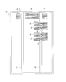
図3は、台脚10の斜視図である。また、図4は、台脚10の底面図である。
台脚10の上面には、レール12が取り付けられている。このレール12の上をユニットベース20はスライドすることができる。よって、機械室の外部への、ユニットベース20の取り外しが容易となっている。したがって、ユニットベース20ごと、機械室内部の機器を取り出すことができ、それら機器のメンテナンスを容易に行うことができる。
台脚10には、第1のメッシュパネル11に加え、第2のメッシュパネル13及び第3のメッシュパネル14が取り付けられている。第1のメッシュパネル11は、台脚10に設けられた第2の開口15、第2の開口16及び第2の開口17を覆っている。第2のメッシュパネル13は、台脚10に設けられた第2の開口18を覆っている。第3のメッシュパネル14は、台脚10に設けられた第2の開口19を覆っている。なお、第1のメッシュパネル11、第2のメッシュパネル13及び第3のメッシュパネル14は、いずれも、空気が通過できる細かい貫通孔を有している。
台脚10の下面には、補強部材41及び補強部材42が取り付けられている。このうち、第2の開口18及び第2の開口19の下方に位置する補強部材42には、上下方向に貫通する補助開口43が設けられている。補助開口43は、第2の開口18または第2の開口19と、上下に並んでいる。なお、必要に応じて、補強部材41と補強部材42のいずれか一方または両方を、台脚10の上側に配置しても良いことは勿論である。その場合、台脚10の上側に配置された補強部材41及び/または補強部材42を、レール12の代わりに用いても良い。
図5は、第1の圧縮機33及び第2の圧縮機34の周辺の平面図である。第1の圧縮機33は4つの基部33aを有しており、基部33aを介して、ユニットベース20上に据え付けられている。第2の圧縮機34は、4つの基部34aを有しており、基部34aを介して、ユニットベース20上に据え付けられている。なお、基部33aの数及び基部34aの数が4に限られないことは言うまでも無い。
第1の圧縮機33及び第2の圧縮機34は、特に限られるわけではないが、平面視で、略楕円形状である。
第1の開口23は、その全領域がユニットベース20への第1の圧縮機33の正射影と重なるように、ユニットベース20に設けられている。換言すると、第1の開口23は、ユニットベース20への第1の圧縮機33の正射影の輪郭に完全に取り囲まれている。あるいは、第1の開口23は、4つの基部33aそれぞれの中心を通過する仮想円の内部に配置されている、と言うことも可能である。
第1の開口24は、その全領域がユニットベース20への第2の圧縮機34の正射影と重なるように、ユニットベース20に設けられている。換言すると、第1の開口24は、ユニットベース20への第2の圧縮機34の正射影の輪郭に完全に取り囲まれている。あるいは、第1の開口24は、4つの基部34aそれぞれの中心を通過する仮想円の内部に配置されている、と言うことも可能である。
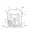
図6は、第1の圧縮機33または第2の圧縮機34の縦断面模式図である。なお、第2の圧縮機34は第1の圧縮機33と同じ構造を有しているので、以下では第1の圧縮機33のみについて説明する。
第1の圧縮機33はケーシング301を有する。ケーシング301の内部にはモータ302が配置されている。モータ302にはクランク機構を介してピストン303が接続されている。ピストン303は、シリンダ304の内部を往復移動可能に配置されている。ケーシング301の一部には、第1の圧縮機33への冷媒入口となる流入口305、及び、第1の圧縮機33からの冷媒出口となる流出口306が取り付けられている。また、ケーシング301の外部には、モータ302へ電力を供給するケーブルや、第1の圧縮機33を制御するための信号が伝わるケーブルが接続される端子箱307が取り付けられている。
ケーシング301の内部には、ピストン303等、ケーシング301の内部で動く部材の摩擦を低減するための潤滑油が封入されている。ケーシング301の底部は、この潤滑油が溜まる潤滑油溜めを構成している。
以上のように構成された冷凍装置1は、次のように作動する。
まず、第1の圧縮機33及び第2の圧縮機34の運転が開始されるとともに、第1の冷媒回路及び第2の冷媒回路中に、冷媒が循環し始める。第1の冷媒回路では以下のように冷媒が循環する。以下、第1の冷媒回路または第1の圧縮機33のみについて説明を行う場合があるが、それらの説明は、第2の冷媒回路または第2の圧縮機34にも当てはまるものである。
第1の冷媒回路においては、第1の圧縮機33で圧縮されるとともに温度上昇した冷媒が、凝縮器31に供給される。凝縮器31に供給された冷媒は、ファン32によって供給された空気と熱交換し、冷却され、凝縮する。なお、ファン32の回転によって、冷凍装置1の外部から、通気部7を通じて、冷却用の空気が誘引される。
凝縮器31で凝縮した冷媒は、図示しない絞り装置に流入して膨張し、続いて、図示しない蒸発器に流入して蒸発する。蒸発器で蒸発する際、冷媒は、冷凍装置1が有する冷却室を冷却する。その後、冷媒は再び第1の圧縮機33に流入し、圧縮される。
以上のように冷凍装置1が作動する際、第1の圧縮機33は、高温になる。それと同時に、第1の圧縮機33から吐出される冷媒も高温となる。その原因は、冷媒の圧縮によって発せられる熱、及び、モータ302及びピストン303等の機械が働くことによって発せられる熱である。
しかしながら、本実施形態に係る冷凍装置1においては、以下に説明するメカニズムによって、第1の圧縮機33が冷却され、ひいては、それらの内部で圧縮される冷媒も冷却される。
まず、ファン32の回転によって生じた気流は、第1の圧縮機33の外面に衝突する。続いて、気流は、第1の開口23を通過して、ユニットベース20の上側の領域から下側の領域に移動する。つまり、本実施形態においては、第1の圧縮機33の下方領域と接触する気流の量を多くすることができる。
前述のとおり、第1の圧縮機33のケーシング301の底部は、この潤滑油が溜まる潤滑油溜めを構成している。よって、第1の圧縮機33の下方領域と接触する気流の量を多くすることによって、ケーシング301を介して気流と潤滑油との熱交換量を多くすることができる。潤滑油はケーシング301内で冷媒に接触し、熱交換を行う役割も果たしている。
すなわち、本実施形態においては、第1の圧縮機33内の冷媒と、第1の圧縮機33の外部を流れる空気との間の熱交換効率を向上させることができ、第1の圧縮機33から吐出される冷媒の温度を低下させることができる。
また、第1の開口23は、ケーシング301の下方から放射される輻射熱が、ユニットベース20によって吸収されるまたは反射されることを無くすることにも寄与している。すなわち、ファン32から気流が供給されなくても、第1の開口23が存在することのみにより、第1の圧縮機33の冷却効率が上がる。
また、本実施形態においては、第1の開口23の全領域は、ユニットベース20への第1の圧縮機33の正射影と重なっている。よって、より効率的に、第1の圧縮機33に衝突した気流を、ユニットベース20の下側の領域に誘導することができ、ひいては、第1の圧縮機33の冷却効率を上げることができる。
なお、第1の開口23の領域の一部が、ユニットベース20への第1の圧縮機33の正射影と重なっていれば、第1の圧縮機33に衝突した気流をユニットベース20の下側へ誘導することが可能である。よって、必ずしも、第1の開口23の全領域が、ユニットベース20への第1の圧縮機33の正射影と重なっていなくてもよい。
また、本実施形態においては、ユニットベース20には、第1の開口23、第1の開口24、及び、冷凍装置1を構成するための部材(例えば凝縮器31)を配置するために必要な開口以外に、開口は設けられていない。よって、第1の開口23または第1の開口24を介してユニットベース20の上側から下側へ移動した気流が、再びユニットベース20の上側に戻ってくることがない。つまり、ユニットベース20の上側領域と下側領域との間で空気の流れが循環しないように、冷凍装置1は構成されている。したがって、第1の圧縮機33を冷却するとともに高温となった空気が、再び第1の圧縮機33に接触し、第1の圧縮機33の冷却効率を低減させることが未然に防止されている。
なお、ユニットベース20に、第1の開口23、第1の開口24、及び、冷凍装置1を構成するための部材を配置するために必要な開口以外に、開口が設けられていても良い。この場合、例えば、ユニットベース20の下側に整流部材を配置し、第1の開口23を介して下側に移動してきた気流が当該開口に向かわないようにすることで、ユニットベース20の上側領域と下側領域との間での空気の循環が生じないようにすることができる。
また、本実施形態においては、機械室の底部を構成する台脚10に、第2の開口15、第2の開口16、第2の開口17、第2の開口18及び第2の開口19が設けられている。よって、第1の開口23または第1の開口24を介してユニットベース20の下側に流れ込んできた気流は、ユニットベース20と台脚10との間に滞留することなく、台脚10の下側に流れ込むことができる。よって、第1の開口23または第1の開口24を介して、ユニットベース20の上側から下側に向かう空気の流れをスムーズにすることができる。
しかも、第2の開口18は、第1の開口23と上下に並んでおり、第2の開口19は、第1の開口24と上下に並んでいる。よって、第1の開口23または第1の開口24を介して台脚10の上に流れ込んできた空気を、よりスムーズに、台脚10の下方に流すことができる。すなわち、第2の開口18及び第2の開口19を、第1の開口23及び第1の開口24と上下に並ぶように配置することで、第1の圧縮機33及び第2の圧縮機34の冷却効率をより向上させることができる。
更に、台脚10の下側に配置されている補強部材41及び補強部材42のうち、第2の開口18及び第2の開口19の下方に位置する補強部材42には、補助開口43が設けられている。補助開口43が設けられている位置は、第2の開口18及び第2の開口19と上下に並ぶ位置、つまり、第1の開口23及び第1の開口24と並ぶ位置である。したがって、第2の開口18または第2の開口19を介して台脚10の下側に流れ込んできた空気の流れを、補強部材42で妨げることなく、よりスムーズに、補強部材42の下方に流すことができる。
前述のとおり、機械室の下方、すなわち、機械室の底部である台脚10の下方には、脚8のおかげで空間が確保されている。よって、第2の開口18等を介して台脚10の下方に流れ込んだ空気は、スムーズに、冷凍装置1の周囲に拡散することができる。ひいては、第1の開口23の上側から下側へ向かう空気の流れをスムーズにすることができる。
なお、本実施形態においては、ユニットベース20には補強部材が設けられていないが、台脚10に設けられている補強部材41及び補強部材42と同様の補強部材が設けられていても良い。ユニットベース20に補強部材が設けられる場合、第1の開口23または第1の開口24と上下に並ぶ位置に、補助開口を設けることで、ユニットベース20の上側領域から下側領域へ向かう空気の流れをスムーズにすることができる。
レール12が第1の開口23または第1の開口24の下方に位置する場合は、レール12に、台脚10の下方に空気を流すための開口が設けられても良いことは勿論である。
また、本実施形態においては、機械室の底部を台脚10が構成しているが、台脚10を省略し、ユニットベース20が機械室の底部を構成しても良い。この場合、機械室内部に異物が混入することを防止するために、第1の開口23及び第1の開口24にメッシュパネル等、空気は自由に流通できるが異物は通過できない部材を配置することが好ましい。
なお、第1の開口23、第1の開口24、第2の開口15、第2の開口16、第2の開口17、第2の開口18、第2の開口19、及び、補助開口43は、冷凍装置1の内部で漏れ出た冷媒を、外部に排出する機能も果たす。これらの開口を設けることにより、例えば、冷媒回路を構成する配管の一部から、万一、可燃性の冷媒が漏れ出るようなことがあっても、機械室内部に冷媒が充満することを防止することができる。
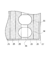
また、本実施形態においては、ユニットベース20が1枚の板状部材で構成されているが、図7に例示されるように、ユニットベース20(すなわち、第1の板部)は、複数の板部材25で構成されていても良い。この場合、第1の開口26は、板部材25同士の隙間で構成することができる。なお、図7中の27は、機械室の壁である。すなわち、第1の板部は、複数枚の板部材で構成され、第1の開口が、それらの板部材の隙間で構成されていてもよい。第2の板部も同様に、複数枚の板部材で構成され、第2の開口が、それらの板部材の隙間で構成されていてもよい。
上記実施形態に係る冷凍装置1は、冷凍室の下方に機械室が配置されていたが、機械室がそのほかの位置に配置されていても良いことは勿論である。例えば、冷凍室の側方に機械室が配置されていても良い。
また、機械室内が、複数、例えば2つの小機械室に分割されていても良い。2つの機械室は、第1の小機械室と、第1の小機械室の上に配置された第2の小機械室とで構成されても良い。この場合、第1の小機械室に配置されている圧縮機の下方に配置される台脚及びユニットベースに、第2の開口及び第1の開口が形成されることで、第1の小機械室に配置されている圧縮機を効率よく冷却することができる。
また、第2の小機械室に配置されている圧縮機の下方であって、第1の小機械室の上方に配置されている板部材、例えばユニットベースに、第1の開口が形成されることで、第2の機械室に配置されている圧縮機を効率よく冷却することができる。もちろん、第1の小機械室の状況次第では、第2の小機械室に配置されている圧縮機の下方であって、第1の小機械室の上方に配置されている板部材に第1の開口を形成しなくても良いことは言うまでも無い。
2018年12月12日出願の特願2018-232328の日本出願に含まれる明細書、特許請求の範囲、図面および要約書の開示内容は、すべて本願に援用される。
本発明は、冷凍装置として好適に利用される。
1 冷凍装置
2 扉
3 ハンドル
4 ヒンジ
5 操作部
6 機械室筐体
7 通気部
8 脚
10 台脚
11 第1のメッシュパネル
12 レール
13 第2のメッシュパネル
14 第3のメッシュパネル
15、16、17、18、19 第2の開口
20 ユニットベース
23、24、26 第1の開口
25 板部材
27 壁
31 凝縮器
32 ファン
33 第1の圧縮機
34 第2の圧縮機
33a、34a 基部
41、42 補強部材
43 補助開口
301 ケーシング
302 モータ
303 ピストン
304 シリンダ
305 流入口
306 流出口
307 端子箱
2 扉
3 ハンドル
4 ヒンジ
5 操作部
6 機械室筐体
7 通気部
8 脚
10 台脚
11 第1のメッシュパネル
12 レール
13 第2のメッシュパネル
14 第3のメッシュパネル
15、16、17、18、19 第2の開口
20 ユニットベース
23、24、26 第1の開口
25 板部材
27 壁
31 凝縮器
32 ファン
33 第1の圧縮機
34 第2の圧縮機
33a、34a 基部
41、42 補強部材
43 補助開口
301 ケーシング
302 モータ
303 ピストン
304 シリンダ
305 流入口
306 流出口
307 端子箱
Claims (10)
- 冷媒回路を構成する圧縮機と、
前記圧縮機の下に配置される第1の板部と、を備え、
前記第1の板部は、前記第1の板部の上側領域と下側領域とをつなげ、且つ、前記第1の板部への前記圧縮機の正射影と重なる第1の開口を有している、
冷凍装置。 - 前記第1の開口の全領域は、前記正射影と重なる、
請求項1に記載の冷凍装置。 - 前記上側領域と前記下側領域との間で空気の流れが循環しないように構成されている、
請求項1または2に記載の冷凍装置。 - 前記第1の板部は、前記第1の開口、及び、前記冷凍装置を構成する部材を配置するために必要な開口以外に、開口を有していない、
請求項3に記載の冷凍装置。 - 前記第1の板部に取り付けられ、且つ、第1の補助開口を有する第1の補強部材を更に備え、
前記第1の補助開口は、前記第1の開口と上下に並ぶ、
請求項1から4のいずれかに記載の冷凍装置。 - 前記第1の板部の下に配置され、且つ、第2の開口を有する第2の板部を更に備える、
請求項1から5のいずれかに記載の冷凍装置。 - 前記第2の開口は、前記第1の開口と上下に並ぶ、
請求項6に記載の冷凍装置。 - 前記第2の板部に取り付けられ、且つ、第2の補助開口を有する第2の補強部材を更に備え、
前記第2の補助開口は、前記第2の開口と上下に並ぶ、
請求項6または7に記載の冷凍装置。 - 前記第1の板部の上に配置され、前記圧縮機に向けて送風するファンを更に備える、
請求項1から8のいずれかに記載の冷凍装置。 - 前記圧縮機は、底部が潤滑油溜まりとなるケーシングを有する、
請求項1から9のいずれかに記載の冷凍装置。
Priority Applications (2)
| Application Number | Priority Date | Filing Date | Title |
|---|---|---|---|
| JP2020559808A JP7157824B2 (ja) | 2018-12-12 | 2019-11-01 | 冷凍装置 |
| JP2022131786A JP2022159557A (ja) | 2018-12-12 | 2022-08-22 | 冷凍装置 |
Applications Claiming Priority (2)
| Application Number | Priority Date | Filing Date | Title |
|---|---|---|---|
| JP2018-232328 | 2018-12-12 | ||
| JP2018232328 | 2018-12-12 |
Publications (1)
| Publication Number | Publication Date |
|---|---|
| WO2020121684A1 true WO2020121684A1 (ja) | 2020-06-18 |
Family
ID=71076306
Family Applications (1)
| Application Number | Title | Priority Date | Filing Date |
|---|---|---|---|
| PCT/JP2019/043028 Ceased WO2020121684A1 (ja) | 2018-12-12 | 2019-11-01 | 冷凍装置 |
Country Status (2)
| Country | Link |
|---|---|
| JP (2) | JP7157824B2 (ja) |
| WO (1) | WO2020121684A1 (ja) |
Citations (8)
| Publication number | Priority date | Publication date | Assignee | Title |
|---|---|---|---|---|
| JPS59178577U (ja) * | 1983-05-18 | 1984-11-29 | 株式会社日立製作所 | 冷蔵庫の箱体構造 |
| JPH03271583A (ja) * | 1990-03-20 | 1991-12-03 | Hitachi Ltd | スクロール圧縮機及びそれを用いたヘリウム液化用冷凍装置 |
| JPH09243234A (ja) * | 1996-03-05 | 1997-09-19 | Hoshizaki Electric Co Ltd | 冷却貯蔵庫における除霜排水蒸発装置 |
| JPH1130464A (ja) * | 1997-07-10 | 1999-02-02 | Hoshizaki Electric Co Ltd | 機械室の部品配置構造 |
| JP2005042953A (ja) * | 2003-07-24 | 2005-02-17 | Hoshizaki Electric Co Ltd | 冷却貯蔵庫 |
| JP2007101018A (ja) * | 2005-09-30 | 2007-04-19 | Sanyo Electric Co Ltd | 冷凍機ユニットにおける圧縮機の冷却構造 |
| JP2009002352A (ja) * | 2008-08-22 | 2009-01-08 | Daikin Ind Ltd | 圧縮機 |
| JP2017015343A (ja) * | 2015-07-03 | 2017-01-19 | 日立アプライアンス株式会社 | 冷蔵庫 |
Family Cites Families (6)
| Publication number | Priority date | Publication date | Assignee | Title |
|---|---|---|---|---|
| JPS5944531A (ja) * | 1982-09-03 | 1984-03-13 | Sanyo Electric Co Ltd | 一体型空気調和機 |
| JPS60176079U (ja) * | 1984-05-02 | 1985-11-21 | ダイキン工業株式会社 | 冷凍ユニツト |
| JPH07103638A (ja) * | 1993-10-07 | 1995-04-18 | Matsushita Refrig Co Ltd | 冷蔵庫 |
| JP3615345B2 (ja) * | 1997-02-19 | 2005-02-02 | 三洋電機株式会社 | 断熱貯蔵庫 |
| JP4189302B2 (ja) * | 2003-11-20 | 2008-12-03 | ホシザキ電機株式会社 | 冷却貯蔵庫 |
| JP2011021798A (ja) * | 2009-07-15 | 2011-02-03 | Panasonic Corp | 保冷米びつ装置 |
-
2019
- 2019-11-01 WO PCT/JP2019/043028 patent/WO2020121684A1/ja not_active Ceased
- 2019-11-01 JP JP2020559808A patent/JP7157824B2/ja active Active
-
2022
- 2022-08-22 JP JP2022131786A patent/JP2022159557A/ja active Pending
Patent Citations (8)
| Publication number | Priority date | Publication date | Assignee | Title |
|---|---|---|---|---|
| JPS59178577U (ja) * | 1983-05-18 | 1984-11-29 | 株式会社日立製作所 | 冷蔵庫の箱体構造 |
| JPH03271583A (ja) * | 1990-03-20 | 1991-12-03 | Hitachi Ltd | スクロール圧縮機及びそれを用いたヘリウム液化用冷凍装置 |
| JPH09243234A (ja) * | 1996-03-05 | 1997-09-19 | Hoshizaki Electric Co Ltd | 冷却貯蔵庫における除霜排水蒸発装置 |
| JPH1130464A (ja) * | 1997-07-10 | 1999-02-02 | Hoshizaki Electric Co Ltd | 機械室の部品配置構造 |
| JP2005042953A (ja) * | 2003-07-24 | 2005-02-17 | Hoshizaki Electric Co Ltd | 冷却貯蔵庫 |
| JP2007101018A (ja) * | 2005-09-30 | 2007-04-19 | Sanyo Electric Co Ltd | 冷凍機ユニットにおける圧縮機の冷却構造 |
| JP2009002352A (ja) * | 2008-08-22 | 2009-01-08 | Daikin Ind Ltd | 圧縮機 |
| JP2017015343A (ja) * | 2015-07-03 | 2017-01-19 | 日立アプライアンス株式会社 | 冷蔵庫 |
Also Published As
| Publication number | Publication date |
|---|---|
| JPWO2020121684A1 (ja) | 2021-10-21 |
| JP2022159557A (ja) | 2022-10-17 |
| JP7157824B2 (ja) | 2022-10-20 |
Similar Documents
| Publication | Publication Date | Title |
|---|---|---|
| KR102170317B1 (ko) | 공기조화기의 실외기 | |
| EP3745059B1 (en) | Built-in refrigerator | |
| US10816225B2 (en) | Movable air conditioner | |
| EP3385626B1 (en) | Outdoor machine | |
| JP4940095B2 (ja) | 電子機器冷却システム | |
| KR101578002B1 (ko) | 냉장고 | |
| JP5017088B2 (ja) | 電子機器冷却装置 | |
| RU2741527C1 (ru) | Холодильник | |
| WO2013046724A1 (ja) | 室外機及び冷凍装置 | |
| US12072139B2 (en) | Refrigerator | |
| WO2013046725A1 (ja) | 室外機及び冷凍装置 | |
| US9353968B2 (en) | Heat source unit of refrigerating apparatus | |
| US11982462B2 (en) | Air conditioner | |
| KR102218078B1 (ko) | 이동형 공기조화기 | |
| JP7157824B2 (ja) | 冷凍装置 | |
| JP2009135287A (ja) | 電子機器冷却装置 | |
| JP2009134522A (ja) | 電子機器冷却システム | |
| KR20250040437A (ko) | 공기조화기의 실외기 | |
| KR20050008334A (ko) | 전기 냉동/냉장 쇼케이스 | |
| US20250020340A1 (en) | Outdoor unit of air conditioner | |
| JP2009134532A (ja) | 電子機器冷却装置 | |
| JP2001324174A (ja) | 冷凍機ユニット | |
| EP4644792A1 (en) | Outdoor unit of air conditioner | |
| JP7058514B2 (ja) | 空気調和装置 | |
| JP2012167856A (ja) | 冷却貯蔵庫 |
Legal Events
| Date | Code | Title | Description |
|---|---|---|---|
| 121 | Ep: the epo has been informed by wipo that ep was designated in this application |
Ref document number: 19894424 Country of ref document: EP Kind code of ref document: A1 |
|
| ENP | Entry into the national phase |
Ref document number: 2020559808 Country of ref document: JP Kind code of ref document: A |
|
| NENP | Non-entry into the national phase |
Ref country code: DE |
|
| 122 | Ep: pct application non-entry in european phase |
Ref document number: 19894424 Country of ref document: EP Kind code of ref document: A1 |