WO2020145313A1 - Tôle en acier électromagnétique orienté ainsi que procédé de fabrication de celle-ci, tôle en acier pour recuit de finition ainsi que procédé de fabrication de celle-ci, et agent de séparation de recuit - Google Patents
Tôle en acier électromagnétique orienté ainsi que procédé de fabrication de celle-ci, tôle en acier pour recuit de finition ainsi que procédé de fabrication de celle-ci, et agent de séparation de recuit Download PDFInfo
- Publication number
- WO2020145313A1 WO2020145313A1 PCT/JP2020/000337 JP2020000337W WO2020145313A1 WO 2020145313 A1 WO2020145313 A1 WO 2020145313A1 JP 2020000337 W JP2020000337 W JP 2020000337W WO 2020145313 A1 WO2020145313 A1 WO 2020145313A1
- Authority
- WO
- WIPO (PCT)
- Prior art keywords
- steel sheet
- primary coating
- annealing
- region
- group
- Prior art date
- Legal status (The legal status is an assumption and is not a legal conclusion. Google has not performed a legal analysis and makes no representation as to the accuracy of the status listed.)
- Ceased
Links
Images


Classifications
-
- C—CHEMISTRY; METALLURGY
- C22—METALLURGY; FERROUS OR NON-FERROUS ALLOYS; TREATMENT OF ALLOYS OR NON-FERROUS METALS
- C22C—ALLOYS
- C22C38/00—Ferrous alloys, e.g. steel alloys
- C22C38/06—Ferrous alloys, e.g. steel alloys containing aluminium
-
- C—CHEMISTRY; METALLURGY
- C21—METALLURGY OF IRON
- C21D—MODIFYING THE PHYSICAL STRUCTURE OF FERROUS METALS; GENERAL DEVICES FOR HEAT TREATMENT OF FERROUS OR NON-FERROUS METALS OR ALLOYS; MAKING METAL MALLEABLE, e.g. BY DECARBURISATION OR TEMPERING
- C21D6/00—Heat treatment of ferrous alloys
- C21D6/008—Heat treatment of ferrous alloys containing Si
-
- C—CHEMISTRY; METALLURGY
- C04—CEMENTS; CONCRETE; ARTIFICIAL STONE; CERAMICS; REFRACTORIES
- C04B—LIME, MAGNESIA; SLAG; CEMENTS; COMPOSITIONS THEREOF, e.g. MORTARS, CONCRETE OR LIKE BUILDING MATERIALS; ARTIFICIAL STONE; CERAMICS; REFRACTORIES; TREATMENT OF NATURAL STONE
- C04B35/00—Shaped ceramic products characterised by their composition; Ceramics compositions; Processing powders of inorganic compounds preparatory to the manufacturing of ceramic products
- C04B35/01—Shaped ceramic products characterised by their composition; Ceramics compositions; Processing powders of inorganic compounds preparatory to the manufacturing of ceramic products based on oxide ceramics
- C04B35/03—Shaped ceramic products characterised by their composition; Ceramics compositions; Processing powders of inorganic compounds preparatory to the manufacturing of ceramic products based on oxide ceramics based on magnesium oxide, calcium oxide or oxide mixtures derived from dolomite
- C04B35/04—Shaped ceramic products characterised by their composition; Ceramics compositions; Processing powders of inorganic compounds preparatory to the manufacturing of ceramic products based on oxide ceramics based on magnesium oxide, calcium oxide or oxide mixtures derived from dolomite based on magnesium oxide
- C04B35/053—Fine ceramics
-
- C—CHEMISTRY; METALLURGY
- C04—CEMENTS; CONCRETE; ARTIFICIAL STONE; CERAMICS; REFRACTORIES
- C04B—LIME, MAGNESIA; SLAG; CEMENTS; COMPOSITIONS THEREOF, e.g. MORTARS, CONCRETE OR LIKE BUILDING MATERIALS; ARTIFICIAL STONE; CERAMICS; REFRACTORIES; TREATMENT OF NATURAL STONE
- C04B35/00—Shaped ceramic products characterised by their composition; Ceramics compositions; Processing powders of inorganic compounds preparatory to the manufacturing of ceramic products
- C04B35/622—Forming processes; Processing powders of inorganic compounds preparatory to the manufacturing of ceramic products
- C04B35/62222—Forming processes; Processing powders of inorganic compounds preparatory to the manufacturing of ceramic products obtaining ceramic coatings
-
- C—CHEMISTRY; METALLURGY
- C04—CEMENTS; CONCRETE; ARTIFICIAL STONE; CERAMICS; REFRACTORIES
- C04B—LIME, MAGNESIA; SLAG; CEMENTS; COMPOSITIONS THEREOF, e.g. MORTARS, CONCRETE OR LIKE BUILDING MATERIALS; ARTIFICIAL STONE; CERAMICS; REFRACTORIES; TREATMENT OF NATURAL STONE
- C04B35/00—Shaped ceramic products characterised by their composition; Ceramics compositions; Processing powders of inorganic compounds preparatory to the manufacturing of ceramic products
- C04B35/622—Forming processes; Processing powders of inorganic compounds preparatory to the manufacturing of ceramic products
- C04B35/626—Preparing or treating the powders individually or as batches ; preparing or treating macroscopic reinforcing agents for ceramic products, e.g. fibres; mechanical aspects section B
- C04B35/62605—Treating the starting powders individually or as mixtures
- C04B35/62625—Wet mixtures
-
- C—CHEMISTRY; METALLURGY
- C21—METALLURGY OF IRON
- C21D—MODIFYING THE PHYSICAL STRUCTURE OF FERROUS METALS; GENERAL DEVICES FOR HEAT TREATMENT OF FERROUS OR NON-FERROUS METALS OR ALLOYS; MAKING METAL MALLEABLE, e.g. BY DECARBURISATION OR TEMPERING
- C21D3/00—Diffusion processes for extraction of non-metals; Furnaces therefor
- C21D3/02—Extraction of non-metals
- C21D3/04—Decarburising
-
- C—CHEMISTRY; METALLURGY
- C21—METALLURGY OF IRON
- C21D—MODIFYING THE PHYSICAL STRUCTURE OF FERROUS METALS; GENERAL DEVICES FOR HEAT TREATMENT OF FERROUS OR NON-FERROUS METALS OR ALLOYS; MAKING METAL MALLEABLE, e.g. BY DECARBURISATION OR TEMPERING
- C21D8/00—Modifying the physical properties of ferrous metals or ferrous alloys by deformation combined with, or followed by, heat treatment
- C21D8/02—Modifying the physical properties of ferrous metals or ferrous alloys by deformation combined with, or followed by, heat treatment during manufacturing of plates or strips
-
- C—CHEMISTRY; METALLURGY
- C21—METALLURGY OF IRON
- C21D—MODIFYING THE PHYSICAL STRUCTURE OF FERROUS METALS; GENERAL DEVICES FOR HEAT TREATMENT OF FERROUS OR NON-FERROUS METALS OR ALLOYS; MAKING METAL MALLEABLE, e.g. BY DECARBURISATION OR TEMPERING
- C21D8/00—Modifying the physical properties of ferrous metals or ferrous alloys by deformation combined with, or followed by, heat treatment
- C21D8/02—Modifying the physical properties of ferrous metals or ferrous alloys by deformation combined with, or followed by, heat treatment during manufacturing of plates or strips
- C21D8/0221—Modifying the physical properties of ferrous metals or ferrous alloys by deformation combined with, or followed by, heat treatment during manufacturing of plates or strips characterised by the working steps
- C21D8/0226—Hot rolling
-
- C—CHEMISTRY; METALLURGY
- C21—METALLURGY OF IRON
- C21D—MODIFYING THE PHYSICAL STRUCTURE OF FERROUS METALS; GENERAL DEVICES FOR HEAT TREATMENT OF FERROUS OR NON-FERROUS METALS OR ALLOYS; MAKING METAL MALLEABLE, e.g. BY DECARBURISATION OR TEMPERING
- C21D8/00—Modifying the physical properties of ferrous metals or ferrous alloys by deformation combined with, or followed by, heat treatment
- C21D8/02—Modifying the physical properties of ferrous metals or ferrous alloys by deformation combined with, or followed by, heat treatment during manufacturing of plates or strips
- C21D8/0221—Modifying the physical properties of ferrous metals or ferrous alloys by deformation combined with, or followed by, heat treatment during manufacturing of plates or strips characterised by the working steps
- C21D8/0236—Cold rolling
-
- C—CHEMISTRY; METALLURGY
- C21—METALLURGY OF IRON
- C21D—MODIFYING THE PHYSICAL STRUCTURE OF FERROUS METALS; GENERAL DEVICES FOR HEAT TREATMENT OF FERROUS OR NON-FERROUS METALS OR ALLOYS; MAKING METAL MALLEABLE, e.g. BY DECARBURISATION OR TEMPERING
- C21D8/00—Modifying the physical properties of ferrous metals or ferrous alloys by deformation combined with, or followed by, heat treatment
- C21D8/12—Modifying the physical properties of ferrous metals or ferrous alloys by deformation combined with, or followed by, heat treatment during manufacturing of articles with special electromagnetic properties
- C21D8/1216—Modifying the physical properties of ferrous metals or ferrous alloys by deformation combined with, or followed by, heat treatment during manufacturing of articles with special electromagnetic properties characterised by the working steps
- C21D8/1233—Cold rolling
-
- C—CHEMISTRY; METALLURGY
- C21—METALLURGY OF IRON
- C21D—MODIFYING THE PHYSICAL STRUCTURE OF FERROUS METALS; GENERAL DEVICES FOR HEAT TREATMENT OF FERROUS OR NON-FERROUS METALS OR ALLOYS; MAKING METAL MALLEABLE, e.g. BY DECARBURISATION OR TEMPERING
- C21D8/00—Modifying the physical properties of ferrous metals or ferrous alloys by deformation combined with, or followed by, heat treatment
- C21D8/12—Modifying the physical properties of ferrous metals or ferrous alloys by deformation combined with, or followed by, heat treatment during manufacturing of articles with special electromagnetic properties
- C21D8/1244—Modifying the physical properties of ferrous metals or ferrous alloys by deformation combined with, or followed by, heat treatment during manufacturing of articles with special electromagnetic properties characterised by the heat treatment
- C21D8/1255—Modifying the physical properties of ferrous metals or ferrous alloys by deformation combined with, or followed by, heat treatment during manufacturing of articles with special electromagnetic properties characterised by the heat treatment with diffusion of elements, e.g. decarburising, nitriding
-
- C—CHEMISTRY; METALLURGY
- C21—METALLURGY OF IRON
- C21D—MODIFYING THE PHYSICAL STRUCTURE OF FERROUS METALS; GENERAL DEVICES FOR HEAT TREATMENT OF FERROUS OR NON-FERROUS METALS OR ALLOYS; MAKING METAL MALLEABLE, e.g. BY DECARBURISATION OR TEMPERING
- C21D8/00—Modifying the physical properties of ferrous metals or ferrous alloys by deformation combined with, or followed by, heat treatment
- C21D8/12—Modifying the physical properties of ferrous metals or ferrous alloys by deformation combined with, or followed by, heat treatment during manufacturing of articles with special electromagnetic properties
- C21D8/1244—Modifying the physical properties of ferrous metals or ferrous alloys by deformation combined with, or followed by, heat treatment during manufacturing of articles with special electromagnetic properties characterised by the heat treatment
- C21D8/1272—Final recrystallisation annealing
-
- C—CHEMISTRY; METALLURGY
- C21—METALLURGY OF IRON
- C21D—MODIFYING THE PHYSICAL STRUCTURE OF FERROUS METALS; GENERAL DEVICES FOR HEAT TREATMENT OF FERROUS OR NON-FERROUS METALS OR ALLOYS; MAKING METAL MALLEABLE, e.g. BY DECARBURISATION OR TEMPERING
- C21D8/00—Modifying the physical properties of ferrous metals or ferrous alloys by deformation combined with, or followed by, heat treatment
- C21D8/12—Modifying the physical properties of ferrous metals or ferrous alloys by deformation combined with, or followed by, heat treatment during manufacturing of articles with special electromagnetic properties
- C21D8/1277—Modifying the physical properties of ferrous metals or ferrous alloys by deformation combined with, or followed by, heat treatment during manufacturing of articles with special electromagnetic properties involving a particular surface treatment
- C21D8/1283—Application of a separating or insulating coating
-
- C—CHEMISTRY; METALLURGY
- C21—METALLURGY OF IRON
- C21D—MODIFYING THE PHYSICAL STRUCTURE OF FERROUS METALS; GENERAL DEVICES FOR HEAT TREATMENT OF FERROUS OR NON-FERROUS METALS OR ALLOYS; MAKING METAL MALLEABLE, e.g. BY DECARBURISATION OR TEMPERING
- C21D9/00—Heat treatment, e.g. annealing, hardening, quenching or tempering, adapted for particular articles; Furnaces therefor
- C21D9/46—Heat treatment, e.g. annealing, hardening, quenching or tempering, adapted for particular articles; Furnaces therefor for sheet metals
-
- C—CHEMISTRY; METALLURGY
- C22—METALLURGY; FERROUS OR NON-FERROUS ALLOYS; TREATMENT OF ALLOYS OR NON-FERROUS METALS
- C22C—ALLOYS
- C22C38/00—Ferrous alloys, e.g. steel alloys
-
- C—CHEMISTRY; METALLURGY
- C22—METALLURGY; FERROUS OR NON-FERROUS ALLOYS; TREATMENT OF ALLOYS OR NON-FERROUS METALS
- C22C—ALLOYS
- C22C38/00—Ferrous alloys, e.g. steel alloys
- C22C38/001—Ferrous alloys, e.g. steel alloys containing N
-
- C—CHEMISTRY; METALLURGY
- C22—METALLURGY; FERROUS OR NON-FERROUS ALLOYS; TREATMENT OF ALLOYS OR NON-FERROUS METALS
- C22C—ALLOYS
- C22C38/00—Ferrous alloys, e.g. steel alloys
- C22C38/004—Very low carbon steels, i.e. having a carbon content of less than 0,01%
-
- C—CHEMISTRY; METALLURGY
- C22—METALLURGY; FERROUS OR NON-FERROUS ALLOYS; TREATMENT OF ALLOYS OR NON-FERROUS METALS
- C22C—ALLOYS
- C22C38/00—Ferrous alloys, e.g. steel alloys
- C22C38/008—Ferrous alloys, e.g. steel alloys containing tin
-
- C—CHEMISTRY; METALLURGY
- C22—METALLURGY; FERROUS OR NON-FERROUS ALLOYS; TREATMENT OF ALLOYS OR NON-FERROUS METALS
- C22C—ALLOYS
- C22C38/00—Ferrous alloys, e.g. steel alloys
- C22C38/02—Ferrous alloys, e.g. steel alloys containing silicon
-
- C—CHEMISTRY; METALLURGY
- C22—METALLURGY; FERROUS OR NON-FERROUS ALLOYS; TREATMENT OF ALLOYS OR NON-FERROUS METALS
- C22C—ALLOYS
- C22C38/00—Ferrous alloys, e.g. steel alloys
- C22C38/04—Ferrous alloys, e.g. steel alloys containing manganese
-
- C—CHEMISTRY; METALLURGY
- C22—METALLURGY; FERROUS OR NON-FERROUS ALLOYS; TREATMENT OF ALLOYS OR NON-FERROUS METALS
- C22C—ALLOYS
- C22C38/00—Ferrous alloys, e.g. steel alloys
- C22C38/16—Ferrous alloys, e.g. steel alloys containing copper
-
- C—CHEMISTRY; METALLURGY
- C22—METALLURGY; FERROUS OR NON-FERROUS ALLOYS; TREATMENT OF ALLOYS OR NON-FERROUS METALS
- C22C—ALLOYS
- C22C38/00—Ferrous alloys, e.g. steel alloys
- C22C38/60—Ferrous alloys, e.g. steel alloys containing lead, selenium, tellurium, or antimony, or more than 0.04% by weight of sulfur
-
- C—CHEMISTRY; METALLURGY
- C23—COATING METALLIC MATERIAL; COATING MATERIAL WITH METALLIC MATERIAL; CHEMICAL SURFACE TREATMENT; DIFFUSION TREATMENT OF METALLIC MATERIAL; COATING BY VACUUM EVAPORATION, BY SPUTTERING, BY ION IMPLANTATION OR BY CHEMICAL VAPOUR DEPOSITION, IN GENERAL; INHIBITING CORROSION OF METALLIC MATERIAL OR INCRUSTATION IN GENERAL
- C23C—COATING METALLIC MATERIAL; COATING MATERIAL WITH METALLIC MATERIAL; SURFACE TREATMENT OF METALLIC MATERIAL BY DIFFUSION INTO THE SURFACE, BY CHEMICAL CONVERSION OR SUBSTITUTION; COATING BY VACUUM EVAPORATION, BY SPUTTERING, BY ION IMPLANTATION OR BY CHEMICAL VAPOUR DEPOSITION, IN GENERAL
- C23C22/00—Chemical surface treatment of metallic material by reaction of the surface with a reactive liquid, leaving reaction products of surface material in the coating, e.g. conversion coatings, passivation of metals
-
- C—CHEMISTRY; METALLURGY
- C23—COATING METALLIC MATERIAL; COATING MATERIAL WITH METALLIC MATERIAL; CHEMICAL SURFACE TREATMENT; DIFFUSION TREATMENT OF METALLIC MATERIAL; COATING BY VACUUM EVAPORATION, BY SPUTTERING, BY ION IMPLANTATION OR BY CHEMICAL VAPOUR DEPOSITION, IN GENERAL; INHIBITING CORROSION OF METALLIC MATERIAL OR INCRUSTATION IN GENERAL
- C23C—COATING METALLIC MATERIAL; COATING MATERIAL WITH METALLIC MATERIAL; SURFACE TREATMENT OF METALLIC MATERIAL BY DIFFUSION INTO THE SURFACE, BY CHEMICAL CONVERSION OR SUBSTITUTION; COATING BY VACUUM EVAPORATION, BY SPUTTERING, BY ION IMPLANTATION OR BY CHEMICAL VAPOUR DEPOSITION, IN GENERAL
- C23C22/00—Chemical surface treatment of metallic material by reaction of the surface with a reactive liquid, leaving reaction products of surface material in the coating, e.g. conversion coatings, passivation of metals
- C23C22/05—Chemical surface treatment of metallic material by reaction of the surface with a reactive liquid, leaving reaction products of surface material in the coating, e.g. conversion coatings, passivation of metals using aqueous solutions
- C23C22/06—Chemical surface treatment of metallic material by reaction of the surface with a reactive liquid, leaving reaction products of surface material in the coating, e.g. conversion coatings, passivation of metals using aqueous solutions using aqueous acidic solutions with pH less than 6
- C23C22/07—Chemical surface treatment of metallic material by reaction of the surface with a reactive liquid, leaving reaction products of surface material in the coating, e.g. conversion coatings, passivation of metals using aqueous solutions using aqueous acidic solutions with pH less than 6 containing phosphates
-
- C—CHEMISTRY; METALLURGY
- C23—COATING METALLIC MATERIAL; COATING MATERIAL WITH METALLIC MATERIAL; CHEMICAL SURFACE TREATMENT; DIFFUSION TREATMENT OF METALLIC MATERIAL; COATING BY VACUUM EVAPORATION, BY SPUTTERING, BY ION IMPLANTATION OR BY CHEMICAL VAPOUR DEPOSITION, IN GENERAL; INHIBITING CORROSION OF METALLIC MATERIAL OR INCRUSTATION IN GENERAL
- C23C—COATING METALLIC MATERIAL; COATING MATERIAL WITH METALLIC MATERIAL; SURFACE TREATMENT OF METALLIC MATERIAL BY DIFFUSION INTO THE SURFACE, BY CHEMICAL CONVERSION OR SUBSTITUTION; COATING BY VACUUM EVAPORATION, BY SPUTTERING, BY ION IMPLANTATION OR BY CHEMICAL VAPOUR DEPOSITION, IN GENERAL
- C23C22/00—Chemical surface treatment of metallic material by reaction of the surface with a reactive liquid, leaving reaction products of surface material in the coating, e.g. conversion coatings, passivation of metals
- C23C22/73—Chemical surface treatment of metallic material by reaction of the surface with a reactive liquid, leaving reaction products of surface material in the coating, e.g. conversion coatings, passivation of metals characterised by the process
- C23C22/74—Chemical surface treatment of metallic material by reaction of the surface with a reactive liquid, leaving reaction products of surface material in the coating, e.g. conversion coatings, passivation of metals characterised by the process for obtaining burned-in conversion coatings
-
- H—ELECTRICITY
- H01—ELECTRIC ELEMENTS
- H01F—MAGNETS; INDUCTANCES; TRANSFORMERS; SELECTION OF MATERIALS FOR THEIR MAGNETIC PROPERTIES
- H01F1/00—Magnets or magnetic bodies characterised by the magnetic materials therefor; Selection of materials for their magnetic properties
- H01F1/01—Magnets or magnetic bodies characterised by the magnetic materials therefor; Selection of materials for their magnetic properties of inorganic materials
- H01F1/03—Magnets or magnetic bodies characterised by the magnetic materials therefor; Selection of materials for their magnetic properties of inorganic materials characterised by their coercivity
- H01F1/12—Magnets or magnetic bodies characterised by the magnetic materials therefor; Selection of materials for their magnetic properties of inorganic materials characterised by their coercivity of soft-magnetic materials
- H01F1/14—Magnets or magnetic bodies characterised by the magnetic materials therefor; Selection of materials for their magnetic properties of inorganic materials characterised by their coercivity of soft-magnetic materials metals or alloys
- H01F1/147—Alloys characterised by their composition
-
- H—ELECTRICITY
- H01—ELECTRIC ELEMENTS
- H01F—MAGNETS; INDUCTANCES; TRANSFORMERS; SELECTION OF MATERIALS FOR THEIR MAGNETIC PROPERTIES
- H01F1/00—Magnets or magnetic bodies characterised by the magnetic materials therefor; Selection of materials for their magnetic properties
- H01F1/01—Magnets or magnetic bodies characterised by the magnetic materials therefor; Selection of materials for their magnetic properties of inorganic materials
- H01F1/03—Magnets or magnetic bodies characterised by the magnetic materials therefor; Selection of materials for their magnetic properties of inorganic materials characterised by their coercivity
- H01F1/12—Magnets or magnetic bodies characterised by the magnetic materials therefor; Selection of materials for their magnetic properties of inorganic materials characterised by their coercivity of soft-magnetic materials
- H01F1/14—Magnets or magnetic bodies characterised by the magnetic materials therefor; Selection of materials for their magnetic properties of inorganic materials characterised by their coercivity of soft-magnetic materials metals or alloys
- H01F1/147—Alloys characterised by their composition
- H01F1/14766—Fe-Si based alloys
- H01F1/14775—Fe-Si based alloys in the form of sheets
-
- H—ELECTRICITY
- H01—ELECTRIC ELEMENTS
- H01F—MAGNETS; INDUCTANCES; TRANSFORMERS; SELECTION OF MATERIALS FOR THEIR MAGNETIC PROPERTIES
- H01F1/00—Magnets or magnetic bodies characterised by the magnetic materials therefor; Selection of materials for their magnetic properties
- H01F1/01—Magnets or magnetic bodies characterised by the magnetic materials therefor; Selection of materials for their magnetic properties of inorganic materials
- H01F1/03—Magnets or magnetic bodies characterised by the magnetic materials therefor; Selection of materials for their magnetic properties of inorganic materials characterised by their coercivity
- H01F1/12—Magnets or magnetic bodies characterised by the magnetic materials therefor; Selection of materials for their magnetic properties of inorganic materials characterised by their coercivity of soft-magnetic materials
- H01F1/14—Magnets or magnetic bodies characterised by the magnetic materials therefor; Selection of materials for their magnetic properties of inorganic materials characterised by their coercivity of soft-magnetic materials metals or alloys
- H01F1/16—Magnets or magnetic bodies characterised by the magnetic materials therefor; Selection of materials for their magnetic properties of inorganic materials characterised by their coercivity of soft-magnetic materials metals or alloys in the form of sheets
-
- C—CHEMISTRY; METALLURGY
- C04—CEMENTS; CONCRETE; ARTIFICIAL STONE; CERAMICS; REFRACTORIES
- C04B—LIME, MAGNESIA; SLAG; CEMENTS; COMPOSITIONS THEREOF, e.g. MORTARS, CONCRETE OR LIKE BUILDING MATERIALS; ARTIFICIAL STONE; CERAMICS; REFRACTORIES; TREATMENT OF NATURAL STONE
- C04B2235/00—Aspects relating to ceramic starting mixtures or sintered ceramic products
- C04B2235/02—Composition of constituents of the starting material or of secondary phases of the final product
- C04B2235/30—Constituents and secondary phases not being of a fibrous nature
- C04B2235/32—Metal oxides, mixed metal oxides, or oxide-forming salts thereof, e.g. carbonates, nitrates, (oxy)hydroxides, chlorides
- C04B2235/3205—Alkaline earth oxides or oxide forming salts thereof, e.g. beryllium oxide
- C04B2235/3208—Calcium oxide or oxide-forming salts thereof, e.g. lime
-
- C—CHEMISTRY; METALLURGY
- C04—CEMENTS; CONCRETE; ARTIFICIAL STONE; CERAMICS; REFRACTORIES
- C04B—LIME, MAGNESIA; SLAG; CEMENTS; COMPOSITIONS THEREOF, e.g. MORTARS, CONCRETE OR LIKE BUILDING MATERIALS; ARTIFICIAL STONE; CERAMICS; REFRACTORIES; TREATMENT OF NATURAL STONE
- C04B2235/00—Aspects relating to ceramic starting mixtures or sintered ceramic products
- C04B2235/02—Composition of constituents of the starting material or of secondary phases of the final product
- C04B2235/30—Constituents and secondary phases not being of a fibrous nature
- C04B2235/32—Metal oxides, mixed metal oxides, or oxide-forming salts thereof, e.g. carbonates, nitrates, (oxy)hydroxides, chlorides
- C04B2235/3205—Alkaline earth oxides or oxide forming salts thereof, e.g. beryllium oxide
- C04B2235/3213—Strontium oxides or oxide-forming salts thereof
-
- C—CHEMISTRY; METALLURGY
- C04—CEMENTS; CONCRETE; ARTIFICIAL STONE; CERAMICS; REFRACTORIES
- C04B—LIME, MAGNESIA; SLAG; CEMENTS; COMPOSITIONS THEREOF, e.g. MORTARS, CONCRETE OR LIKE BUILDING MATERIALS; ARTIFICIAL STONE; CERAMICS; REFRACTORIES; TREATMENT OF NATURAL STONE
- C04B2235/00—Aspects relating to ceramic starting mixtures or sintered ceramic products
- C04B2235/02—Composition of constituents of the starting material or of secondary phases of the final product
- C04B2235/30—Constituents and secondary phases not being of a fibrous nature
- C04B2235/32—Metal oxides, mixed metal oxides, or oxide-forming salts thereof, e.g. carbonates, nitrates, (oxy)hydroxides, chlorides
- C04B2235/3205—Alkaline earth oxides or oxide forming salts thereof, e.g. beryllium oxide
- C04B2235/3215—Barium oxides or oxide-forming salts thereof
-
- C—CHEMISTRY; METALLURGY
- C04—CEMENTS; CONCRETE; ARTIFICIAL STONE; CERAMICS; REFRACTORIES
- C04B—LIME, MAGNESIA; SLAG; CEMENTS; COMPOSITIONS THEREOF, e.g. MORTARS, CONCRETE OR LIKE BUILDING MATERIALS; ARTIFICIAL STONE; CERAMICS; REFRACTORIES; TREATMENT OF NATURAL STONE
- C04B2235/00—Aspects relating to ceramic starting mixtures or sintered ceramic products
- C04B2235/02—Composition of constituents of the starting material or of secondary phases of the final product
- C04B2235/30—Constituents and secondary phases not being of a fibrous nature
- C04B2235/32—Metal oxides, mixed metal oxides, or oxide-forming salts thereof, e.g. carbonates, nitrates, (oxy)hydroxides, chlorides
- C04B2235/3224—Rare earth oxide or oxide forming salts thereof, e.g. scandium oxide
- C04B2235/3225—Yttrium oxide or oxide-forming salts thereof
-
- C—CHEMISTRY; METALLURGY
- C04—CEMENTS; CONCRETE; ARTIFICIAL STONE; CERAMICS; REFRACTORIES
- C04B—LIME, MAGNESIA; SLAG; CEMENTS; COMPOSITIONS THEREOF, e.g. MORTARS, CONCRETE OR LIKE BUILDING MATERIALS; ARTIFICIAL STONE; CERAMICS; REFRACTORIES; TREATMENT OF NATURAL STONE
- C04B2235/00—Aspects relating to ceramic starting mixtures or sintered ceramic products
- C04B2235/02—Composition of constituents of the starting material or of secondary phases of the final product
- C04B2235/30—Constituents and secondary phases not being of a fibrous nature
- C04B2235/32—Metal oxides, mixed metal oxides, or oxide-forming salts thereof, e.g. carbonates, nitrates, (oxy)hydroxides, chlorides
- C04B2235/3224—Rare earth oxide or oxide forming salts thereof, e.g. scandium oxide
- C04B2235/3227—Lanthanum oxide or oxide-forming salts thereof
-
- C—CHEMISTRY; METALLURGY
- C04—CEMENTS; CONCRETE; ARTIFICIAL STONE; CERAMICS; REFRACTORIES
- C04B—LIME, MAGNESIA; SLAG; CEMENTS; COMPOSITIONS THEREOF, e.g. MORTARS, CONCRETE OR LIKE BUILDING MATERIALS; ARTIFICIAL STONE; CERAMICS; REFRACTORIES; TREATMENT OF NATURAL STONE
- C04B2235/00—Aspects relating to ceramic starting mixtures or sintered ceramic products
- C04B2235/02—Composition of constituents of the starting material or of secondary phases of the final product
- C04B2235/30—Constituents and secondary phases not being of a fibrous nature
- C04B2235/32—Metal oxides, mixed metal oxides, or oxide-forming salts thereof, e.g. carbonates, nitrates, (oxy)hydroxides, chlorides
- C04B2235/3224—Rare earth oxide or oxide forming salts thereof, e.g. scandium oxide
- C04B2235/3229—Cerium oxides or oxide-forming salts thereof
-
- C—CHEMISTRY; METALLURGY
- C04—CEMENTS; CONCRETE; ARTIFICIAL STONE; CERAMICS; REFRACTORIES
- C04B—LIME, MAGNESIA; SLAG; CEMENTS; COMPOSITIONS THEREOF, e.g. MORTARS, CONCRETE OR LIKE BUILDING MATERIALS; ARTIFICIAL STONE; CERAMICS; REFRACTORIES; TREATMENT OF NATURAL STONE
- C04B2235/00—Aspects relating to ceramic starting mixtures or sintered ceramic products
- C04B2235/02—Composition of constituents of the starting material or of secondary phases of the final product
- C04B2235/50—Constituents or additives of the starting mixture chosen for their shape or used because of their shape or their physical appearance
- C04B2235/54—Particle size related information
- C04B2235/5418—Particle size related information expressed by the size of the particles or aggregates thereof
- C04B2235/5436—Particle size related information expressed by the size of the particles or aggregates thereof micrometer sized, i.e. from 1 to 100 micron
-
- C—CHEMISTRY; METALLURGY
- C04—CEMENTS; CONCRETE; ARTIFICIAL STONE; CERAMICS; REFRACTORIES
- C04B—LIME, MAGNESIA; SLAG; CEMENTS; COMPOSITIONS THEREOF, e.g. MORTARS, CONCRETE OR LIKE BUILDING MATERIALS; ARTIFICIAL STONE; CERAMICS; REFRACTORIES; TREATMENT OF NATURAL STONE
- C04B2235/00—Aspects relating to ceramic starting mixtures or sintered ceramic products
- C04B2235/02—Composition of constituents of the starting material or of secondary phases of the final product
- C04B2235/50—Constituents or additives of the starting mixture chosen for their shape or used because of their shape or their physical appearance
- C04B2235/54—Particle size related information
- C04B2235/5418—Particle size related information expressed by the size of the particles or aggregates thereof
- C04B2235/5445—Particle size related information expressed by the size of the particles or aggregates thereof submicron sized, i.e. from 0,1 to 1 micron
-
- C—CHEMISTRY; METALLURGY
- C04—CEMENTS; CONCRETE; ARTIFICIAL STONE; CERAMICS; REFRACTORIES
- C04B—LIME, MAGNESIA; SLAG; CEMENTS; COMPOSITIONS THEREOF, e.g. MORTARS, CONCRETE OR LIKE BUILDING MATERIALS; ARTIFICIAL STONE; CERAMICS; REFRACTORIES; TREATMENT OF NATURAL STONE
- C04B2235/00—Aspects relating to ceramic starting mixtures or sintered ceramic products
- C04B2235/02—Composition of constituents of the starting material or of secondary phases of the final product
- C04B2235/50—Constituents or additives of the starting mixture chosen for their shape or used because of their shape or their physical appearance
- C04B2235/54—Particle size related information
- C04B2235/5463—Particle size distributions
-
- C—CHEMISTRY; METALLURGY
- C04—CEMENTS; CONCRETE; ARTIFICIAL STONE; CERAMICS; REFRACTORIES
- C04B—LIME, MAGNESIA; SLAG; CEMENTS; COMPOSITIONS THEREOF, e.g. MORTARS, CONCRETE OR LIKE BUILDING MATERIALS; ARTIFICIAL STONE; CERAMICS; REFRACTORIES; TREATMENT OF NATURAL STONE
- C04B2235/00—Aspects relating to ceramic starting mixtures or sintered ceramic products
- C04B2235/02—Composition of constituents of the starting material or of secondary phases of the final product
- C04B2235/50—Constituents or additives of the starting mixture chosen for their shape or used because of their shape or their physical appearance
- C04B2235/54—Particle size related information
- C04B2235/5463—Particle size distributions
- C04B2235/5472—Bimodal, multi-modal or multi-fraction
-
- C—CHEMISTRY; METALLURGY
- C21—METALLURGY OF IRON
- C21D—MODIFYING THE PHYSICAL STRUCTURE OF FERROUS METALS; GENERAL DEVICES FOR HEAT TREATMENT OF FERROUS OR NON-FERROUS METALS OR ALLOYS; MAKING METAL MALLEABLE, e.g. BY DECARBURISATION OR TEMPERING
- C21D2201/00—Treatment for obtaining particular effects
- C21D2201/05—Grain orientation
-
- C—CHEMISTRY; METALLURGY
- C21—METALLURGY OF IRON
- C21D—MODIFYING THE PHYSICAL STRUCTURE OF FERROUS METALS; GENERAL DEVICES FOR HEAT TREATMENT OF FERROUS OR NON-FERROUS METALS OR ALLOYS; MAKING METAL MALLEABLE, e.g. BY DECARBURISATION OR TEMPERING
- C21D8/00—Modifying the physical properties of ferrous metals or ferrous alloys by deformation combined with, or followed by, heat treatment
- C21D8/12—Modifying the physical properties of ferrous metals or ferrous alloys by deformation combined with, or followed by, heat treatment during manufacturing of articles with special electromagnetic properties
- C21D8/1244—Modifying the physical properties of ferrous metals or ferrous alloys by deformation combined with, or followed by, heat treatment during manufacturing of articles with special electromagnetic properties characterised by the heat treatment
- C21D8/1261—Modifying the physical properties of ferrous metals or ferrous alloys by deformation combined with, or followed by, heat treatment during manufacturing of articles with special electromagnetic properties characterised by the heat treatment following hot rolling
-
- Y—GENERAL TAGGING OF NEW TECHNOLOGICAL DEVELOPMENTS; GENERAL TAGGING OF CROSS-SECTIONAL TECHNOLOGIES SPANNING OVER SEVERAL SECTIONS OF THE IPC; TECHNICAL SUBJECTS COVERED BY FORMER USPC CROSS-REFERENCE ART COLLECTIONS [XRACs] AND DIGESTS
- Y02—TECHNOLOGIES OR APPLICATIONS FOR MITIGATION OR ADAPTATION AGAINST CLIMATE CHANGE
- Y02P—CLIMATE CHANGE MITIGATION TECHNOLOGIES IN THE PRODUCTION OR PROCESSING OF GOODS
- Y02P10/00—Technologies related to metal processing
- Y02P10/20—Recycling
Definitions
- the present invention relates to a grain-oriented electrical steel sheet, a steel sheet for finish annealing, an annealing separator, a method for producing a grain-oriented electrical steel sheet, and a method for manufacturing a steel sheet for finish annealing.
- Oriented electrical steel sheet is a steel sheet containing 0.5 to 7% by mass of Si and having crystal orientations accumulated in ⁇ 110 ⁇ 001> orientation (goss orientation). A catastrophic grain growth phenomenon called secondary recrystallization is used to control the crystal orientation.
- the method of manufacturing grain-oriented electrical steel is as follows. A slab is heated and hot rolling is performed to manufacture a hot rolled steel sheet. The hot rolled steel sheet is annealed as necessary. Pickling the hot rolled steel sheet. The hot-rolled steel sheet after pickling is cold-rolled at a cold rolling ratio of 80% or more to produce a cold-rolled steel sheet. Decarburization annealing is performed on the cold-rolled steel sheet to develop primary recrystallization. Finish annealing is performed on the cold-rolled steel sheet after decarburization annealing to cause secondary recrystallization. Through the above steps, the grain-oriented electrical steel sheet is manufactured.
- an annealing separating agent containing MgO as a main component is attached to the surface of the cold rolled steel sheet.
- the method is carried out by applying an aqueous slurry containing an annealing separator component to a cold rolled steel sheet and drying. After the cold-rolled steel sheet to which the annealing separating agent is attached is wound on a coil, finish annealing is performed.
- MgO in the annealing separator reacts with SiO 2 in the internal oxide layer formed on the surface of the cold-rolled steel sheet during decarburization annealing, and mainly contains forsterite (Mg 2 SiO 4 ).
- a primary coating is formed on the steel plate surface.
- an insulating coating liquid also referred to as a secondary coating
- the primary coating and the insulating coating have a coefficient of thermal expansion smaller than that of the base steel sheet. Therefore, the primary coating, together with the insulating coating, imparts tension to the base steel sheet to reduce iron loss.
- the primary coating further enhances the adhesion of the insulating coating to the base steel sheet. Higher adhesion of the primary coating to the base steel sheet is preferred.
- a base material steel plate contains a magnetic property improving element (Cu, Sn, Sb, Bi, Te, Pb, Se, etc.) that strengthens the action of an inhibitor (precipitate that suppresses normal grain growth). .. Thereby, the integration of the crystal orientation in the Goss orientation is enhanced, and the magnetic flux density of the grain-oriented electrical steel sheet can be enhanced.
- a magnetic property improving element Cu, Sn, Sb, Bi, Te, Pb, Se, etc.
- the base material steel plate/primary coating interface is formed so that the interface energy is as low as possible, the aforementioned base material steel plate/primary coating interface is flat.
- the base steel sheet contains a magnetic property improving element, it tends to become flatter. If the base steel sheet/primary coating interface becomes flatter, the insertion structure of the primary coating that creates the physical bonding force between the primary coating and the base steel sheet is lost, and the primary coating is transferred to the base steel sheet. Adhesion of is reduced. In particular, due to the compressive stress generated by bending, peeling is likely to occur, and the adhesiveness is significantly reduced.
- Patent Documents 4 and 5 disclose techniques for improving the adhesion of the primary coating to the steel sheet.
- Patent Document 4 0.001 to 0.1 mass% of Ce is contained in the slab component, and a primary coating film containing 0.01 to 1000 mg/m 2 of Ce is formed on the surface of the steel sheet.
- the grain-oriented electrical steel sheet contains Si: 1.8 to 7% by mass, has a primary coating containing forsterite as a main component on its surface, and Ce, La, Pr, Nd is contained in the primary coating.
- Sc, Y in an amount of 0.001 to 1000 mg/m 2 per one side in a basis weight, and one or more of Sr, Ca, Ba in a basis weight in a total amount per side. It is characterized by containing 0.01 to 100 mg/m 2 .
- Patent Document 5 discloses a manufacturing method including a series of steps in which an annealing separator is applied to the surface of a base steel sheet subjected to decarburization annealing, followed by drying and finish annealing.
- a method for producing a grain-oriented electrical steel sheet excellent in magnetic properties and primary coating adhesion characterized in that two or more kinds are contained in a total amount of 0.01 to 14 mass% with respect to MgO in terms of metal. It is disclosed.
- JP-A-6-88171 Japanese Patent Laid-Open No. 8-269552 JP, 2005-290446, A JP, 2008-127634, A JP 2012-214902 A
- the adhesion of the primary coating is referred to as an effect of reducing end surface peeling caused by shearing, but as to peeling resistance to bending, bending of about several tens of mm ⁇ is required. It is not evaluated as being less worked than shearing. Since the peeling behavior due to shearing and bending is different, it is more difficult than conventional to secure the adhesion of the primary coating to the base material steel sheet as an electromagnetic steel sheet for iron core manufacturing methods with a high degree of bending in recent years. Adhesion is required so that the primary coating does not peel off when subjected to bending, and even a material having no problem with peeling resistance of the sheared end face may not necessarily obtain severe resistance to bending.
- gas such as nitrogen contained in the steel plate escapes.
- the primary coating slows gas permeation.
- the gas pressure becomes high at the interface between the primary coating and the base metal, and the primary coating may be blown off and destroyed.
- dot-shaped exposed base metal portions having a size that can be visually identified appear on the surface of the steel sheet. If these dot-shaped exposed portions of the base material are generated at a somewhat high number density over a wide range on the surface of the steel sheet, they become serious defects in terms of insulation and appearance quality. Since the above-mentioned technique for improving the adhesion of the primary coating does not necessarily suppress the point defects, a control technique of the primary coating form that does not cause the point defects is required.
- the object of the present invention is excellent in magnetic properties and adhesion to the base material steel sheet of the primary coating, the grain-oriented electrical steel sheet with few defects in which the base material is exposed in spots, and finish annealing steel sheet, annealing separator, direction To provide a method for producing a strong electromagnetic steel sheet and a method for producing a steel sheet for finish annealing.
- the present invention controls and regulates the characteristics of the structure of the interface between the primary coating of a grain-oriented electrical steel sheet and the base material steel sheet to specify the structure of the primary coating.
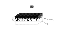
- the primary coating is divided into two regions in the plate thickness direction based on the geometrical features schematically shown in FIG. 1 to define the structure in each region.
- the term "surface oxide layer (1)” on the surface side and the term "inserted oxide layer (2)" on the base material steel sheet side are used to express two regions.
- the surface oxide layer (1) is a plate thickness at which a primary coating part that covers the surface of the base steel sheet relatively uniformly (hereinafter, this may be referred to as “surface oxide”) is present. This is the area of the direction.
- the inlaid oxide layer (2) is a region in the plate thickness direction in which a primary coating portion (hereinafter, sometimes referred to as “inlaid oxide”) that has digged into the base steel sheet exists.
- the reference value H0 of the depth for dividing the two will be described later.
- the structure of the interface is defined by the morphological characteristics of the primary coating observed from the mother steel sheet side. Details will be described later together with the measuring method.
- the structure of the interface between the primary coating film and the base steel sheet, particularly the characteristic of the shape, may be generally expressed by using the term "root".
- the interface between the primary coating of the grain-oriented electrical steel sheet and the base steel sheet has an uneven shape in which the inlaid oxide penetrates into the base steel sheet.
- the penetration depth of the embedded oxide becomes deep and the number density (number/ ⁇ m 3 ) of the number of oxide particles increases, the adhesion of the primary coating to the base material steel plate increases due to the so-called anchor effect.
- the infiltrated oxide penetrates too much into the base steel sheet, it becomes a factor that hinders the crystal grain growth of the steel sheet during secondary recrystallization and the domain wall movement during magnetization, deteriorating the magnetic properties.
- the primary coating has the effect of imparting tension to the steel sheet and reducing iron loss.
- the surface oxide layer (1) of the primary coating preferably has a high content of Mg 2 SiO 4 having a small linear expansion coefficient, and the surface oxide layer (1) is thick. Is desirable.
- the present inventors have found that the magnetic properties of the grain-oriented electrical steel sheet containing a magnetic property improving element and the annealing containing Y, La, Ce compounds and Ca, Sr, Ba compounds.
- the adhesiveness of the primary coating formed by using the separating agent was investigated and examined.
- the present inventors have obtained the following findings.
- one or more elements selected from the group consisting of Y, La, and Ce are collectively referred to as “Y group element”, and one or more elements selected from the group consisting of Ca, Sr, and Ba.
- the elements may be collectively described as "Ca group element".
- the coating adhesion to the shearing process may be sufficient, but the coating adhesion to the bending process may not be sufficiently obtained. .. Further, if a large amount of the Y group element and the Ca group element are added at the same time in order to improve the adhesion of the coating film against bending, iron loss and magnetic flux density may decrease. Further, even if the surface area of the inlaid oxide layer (2) is increased in order to control the morphology of the primary coating and enhance the coating adhesion, the primary coating is blown off by the gas generated from the steel sheet during finish annealing. As a result, defects may occur in which the base material is exposed in spots.
- the embedded oxide layer (2) becomes thick. This improves the film adhesion to shearing. Further, when the annealing separator contains a Ca group element, the number density of the inlaid oxide layer (2) of the formed primary coating increases, and the coating adhesion to shearing improves. Furthermore, as the total content of the Ca group elements specified below in the primary coating, the total content of the Ca group elements contained as impurities in the MgO raw material powder and the compound of the Ca group element contained outside the MgO raw material powder If the content of is adjusted to an appropriate ratio, the adhesion of the coating film to bending is enhanced, deterioration of magnetic properties is suppressed, and point defects are also suppressed.
- the thickness of the surface oxide layer (1) becomes uniform and the Mg 2 SiO 4 phase increases. Furthermore, the embedded oxide layer (2) becomes longer not only in the plate thickness direction but also in the longitudinal width direction.
- the improvement of the film adhesion to bending is that the thickness of the surface oxide layer (1) becomes uniform, and the local stress is concentrated on the region where the thickness of the surface oxide layer (1) during bending is thin. It is thought that this is due to the avoidance of. Further, it is considered that the improvement of the magnetic properties is caused by the increase in the tension acting on the steel sheet because the amount of Mg 2 SiO 4 phase in the surface oxide layer (1) increases.
- the primary coating having such good characteristics is characterized not only by the shape of the interface irregularities but also by the morphology of Al existing near the interface of the primary coating. Further, the characteristics of the annealing separator used to form such a primary coating were clarified. Since the interface between the base steel sheet and the primary coating has a complicated three-dimensional shape having irregularities as shown in FIG. 1, an attempt was made to define the structural characteristics of the interface having this three-dimensional shape.
- the steel sheet for finish annealing for producing the grain-oriented electrical steel sheet satisfies the following condition (9).
- (9) Number density D42 of particles containing a Ca group element in the Ca group element concentrated region of the annealing separator layer: 0.005 to 1.400 particles/ ⁇ m 3 .
- the primary separator and the annealing separator capable of forming the annealing separator layer satisfy the following conditions (10) to (17).
- the gist of the present invention obtained from these findings is as follows.
- the grain-oriented electrical steel sheet according to the present invention is, in mass %, C: 0.0050% or less, Si: 2.5 to 4.5%, Mn: 0.02 to 0.20%, from the group consisting of S and Se.
- One or more selected elements 0.005% or less in total, sol.
- a primary coating containing 2 SiO 4 as a main component and in the plate thickness direction of the steel plate, the primary coating surface of the steel plate when the direction from the primary coating to the base steel plate is positive
- the information of the unevenness is projected and developed on a plane parallel to the steel plate surface, and the median value of the surface height of the primary coating on the base material steel plate side is defined as H0.
- the primary coating is classified as an "inserted oxide layer area” and the primary coating existing on the primary coating side with respect to H0 + 0.2 ⁇ m is classified as a "surface oxide layer area", and the information of the primary coating is parallel to the steel sheet surface.
- the maximum value of the characteristic X-ray intensity of Al (aluminum) is specified in the characteristic X-ray intensity and unevenness correlation distribution chart projected and developed on a flat surface, and 20% or more of the maximum value of the characteristic X-ray intensity of Al is specified.
- the primary coating is (1) Number density D3 of the Al concentrated region: 0.015 to 0.150/ ⁇ m 2 , (2) (Area S5 of the area which is the inlaid oxide layer area and is the Al concentrated area)/(Area S3 of the Al concentrated area) ⁇ 0.30, (3) Distance H5 obtained by subtracting H0 from the average value of the height in the plate thickness direction of the area that is the inlaid oxide layer area and that is the Al concentrated area, H5: 0.4 to 4.0 ⁇ m, (4) (peripheral length L5 of the area that is the above-mentioned inlaid oxide layer area and that is the above Al concentrated area)/(observation area S0): 0.020 to 0.500 ⁇ m/ ⁇ m 2 , (5) It is characterized in that the condition of (area S1 of the fitting oxide layer region)/(observation area S0) ⁇ 0.15 is satisfied.
- the primary coating contains one or more elements selected from the group consisting of Y, La, and Ce, and one or more elements selected from the group consisting of Ca, Sr, and Ba.
- the maximum value of the characteristic X-ray intensity of each of Ca, Sr, and Ba is specified, and 20% or more of the maximum value of the characteristic X-ray intensity of Ca is contained.
- the area where the characteristic X-ray intensity of Ca is obtained the area where the characteristic X-ray intensity of Sr is 20% or more of the maximum value of the characteristic X-ray intensity of Sr, and the maximum value of the characteristic X-ray intensity of Ba.
- the steel sheet for finish annealing for producing the grain-oriented electrical steel sheet is, in mass %, C: 0.1% or less, Si: 2.5 to 4.5%, Mn: 0.02 to 0.20. %, one or more elements selected from the group consisting of S and Se: 0.005 to 0.07% in total, sol.
- the maximum value of the characteristic X-ray intensity of each of Ca, Sr, and Ba is specified, and a region where the characteristic X-ray intensity of Ca of 20% or more of the maximum value of the characteristic X-ray intensity of Ca is obtained, and the characteristic X of Sr.
- a region where a characteristic X-ray intensity of Sr of 20% or more of the maximum value of the line intensity is obtained and a region where the characteristic X-ray intensity of Ba of 20% or more of the maximum value of the characteristic X-ray intensity of Ba is combined.
- the annealing separator layer is (9) Ca, Sr in the Ca group element enriched region existing in a region of 0 to 3.0 ⁇ m from the base steel plate surface. , Ba satisfying the number density D42: 0.005 to 1.400 particles/ ⁇ m 3 of particles containing at least one element selected from the group consisting of Ba, Ba and Ba.
- the annealing separating agent according to the present invention is an annealing separating agent containing MgO as a main component, and comprises one or more elements selected from the group consisting of Y, La, and Ce, and a group consisting of Ca, Sr, and Ba. Containing one or more elements selected, the content of Mg, Y, La, Ce, Ca, Sr, Ba contained in the annealing separator with respect to the content of MgO contained in the annealing separator.
- the production method of the grain-oriented electrical steel sheet according to the present invention comprises, in mass%, C: 0.1% or less, Si: 2.5 to 4.5%, Mn: 0.02 to 0.20%, S and Se.
- the manufacturing method of the steel sheet for finish annealing is, in mass %, C: 0.1% or less, Si: 2.5 to 4.5%, Mn: 0.02 to 0.20%, a group consisting of S and Se.
- the method is characterized by comprising a step of producing and a step of applying an aqueous slurry on the surface of the decarburized annealed plate and drying the same, wherein the aqueous slurry contains the above-mentioned annealing separator.
- the grain-oriented electrical steel sheet according to the present invention has excellent magnetic properties and excellent adhesion of the primary coating to the base material steel sheet.
- the method for producing a grain-oriented electrical steel sheet according to the present invention can produce the grain-oriented electrical steel sheet described above.
- the annealing separator according to the present invention is applied to the above manufacturing method, whereby the grain-oriented electrical steel sheet of the present invention can be manufactured.
- the steel sheet for finish annealing according to the present invention is for producing the grain-oriented electrical steel sheet of the present invention.
- the method for producing a steel sheet for finish annealing according to the present invention can produce the steel sheet for finish annealing described above.
- the surface of the side that was in close contact with the base material steel sheet of the primary coating separated from the grain-oriented electrical steel sheet is observed.
- This observation surface is analyzed by a scanning confocal laser scanning microscope to obtain the unevenness distribution of the interface (information in the depth direction of the interface). Further, the observation surface is analyzed using SEM-EDS, and the concentration distribution of various elements existing in the primary coating is obtained from the characteristic X-ray intensity.
- the obtained information is the information of the primary coating having a three-dimensional structure (concavities and convexities, characteristic X-ray intensity) on the steel sheet surface. It is projected on parallel planes. It is first noted that the following description of the interface in the present specification uses the "features on the projection plane". For example, the “area” related to the structure of the interface is the area obtained on the projection plane, and the region where the element exists is specified based on the characteristic X-ray intensity of the element obtained on the projection plane.
- the characteristics obtained on these projection planes can well define the characteristics of the present invention, and the present invention will be described by the information of the primary film on these projection planes. It goes without saying that does not impair the meaning of the present invention.
- the notation “A to B” for the numerical values A and B means “not less than A and not more than B” unless otherwise specified. When a unit is attached only to the numerical value B in this notation, the unit is also applied to the numerical value A.
- the “main component” means a component contained in a certain substance in an amount of 50% by mass or more, preferably 70% by mass or more, and more preferably 90% by mass or more.
- a method for producing a grain-oriented electrical steel sheet and a grain-oriented electrical steel sheet according to the present invention an annealing separator used in the production of a grain-oriented electrical steel sheet, a finish annealing steel sheet for producing a grain-oriented electrical steel sheet and a finish annealing steel sheet.
- the manufacturing method will be described in detail.
- % relating to the content of an element means mass% unless otherwise specified.
- the grain-oriented electrical steel sheet according to the present invention comprises a base material steel sheet and a primary coating formed on the surface of the base material steel sheet.
- the chemical composition of the base steel sheet forming the grain-oriented electrical steel sheet described above contains the following elements.
- the feature of the present invention resides in the primary coating, and the base steel sheet does not need to be special.
- the base steel sheet is produced by performing cold rolling using a hot-rolled steel sheet having a chemical composition described later, and the components lost during finish annealing. Therefore, the chemical composition of the base steel sheet and the chemical composition of the hot-rolled steel sheet constituting the grain-oriented electrical steel sheet are significantly different.
- Carbon (C) is an element effective for controlling the structure until the completion of the decarburization annealing step in the manufacturing process, but if the C content exceeds 0.0050%, it is a product plate. The magnetic properties of the grain-oriented electrical steel sheet deteriorate. Therefore, the C content is 0.0050% or less. It is preferable that the C content is as low as possible. However, even if the C content is reduced to less than 0.0001%, only the manufacturing cost is required, and the above effect does not change so much. Therefore, the preferable lower limit of the C content is 0.0001%.
- Si 2.5-4.5%
- Si increases the electrical resistance of steel and reduces eddy current loss. If the Si content is less than 2.5%, the above effect cannot be sufficiently obtained. On the other hand, if the Si content exceeds 4.5%, the cold workability of the steel deteriorates. Therefore, the Si content is 2.5 to 4.5%.
- the lower limit of the Si content is preferably 2.6%, and more preferably 2.8%.
- the upper limit of the Si content is preferably 4.0%, and more preferably 3.8%.
- Mn 0.02 to 0.20%
- Manganese (Mn) combines with S and Se described later to form MnS and MnSe during the manufacturing process. These precipitates function as inhibitors (inhibitors of normal grain growth) and cause secondary recrystallization in steel. Mn further enhances the hot workability of steel. If the Mn content is less than 0.02%, the above effect cannot be sufficiently obtained. On the other hand, if the Mn content exceeds 0.20%, secondary recrystallization does not occur and the magnetic properties of the steel may deteriorate. Therefore, the Mn content is 0.02 to 0.20%.
- the preferable lower limit of the Mn content is 0.03%, more preferably 0.04%.
- the preferable upper limit of the Mn content is 0.13%, more preferably 0.1%.
- One or more elements selected from the group consisting of S and Se 0.005% or less in total Sulfur (S) content and selenium (Se) combine with Mn during the manufacturing process to function as an inhibitor. MnS and MnSe are formed. However, if the total content of these elements exceeds 0.005%, the magnetic properties deteriorate due to the remaining inhibitors. Further, segregation of S and Se may cause surface defects in the grain-oriented electrical steel sheet. Therefore, in the grain-oriented electrical steel sheet, the total content of one or more elements selected from the group consisting of S and Se is 0.005% or less. The total content of S and Se in the grain-oriented electrical steel sheet is preferably as low as possible.
- the preferable lower limit of the total content of at least one selected from the group consisting of S and Se in the grain-oriented electrical steel sheet is 0.0001%.
- sol. Al 0.010% or less
- Aluminum (Al) combines with N to form AlN and functions as an inhibitor during the production process of the grain-oriented electrical steel sheet.
- the Al content is 0.010% or less.
- the preferable upper limit of the Al content is 0.004%, and more preferably 0.003%. sol.
- the Al content is preferably as low as possible.
- the preferable lower limit of the Al content is 0.0001%. In the present specification, sol.
- Al means acid-soluble Al. Therefore, sol.
- the Al content is the content of acid-soluble Al.
- Al which is a feature of the primary coating of the present invention, is derived from the base steel sheet, as will be described later. Therefore, at first glance, the fact that the Al content of the base steel sheet is zero seems to contradict with the presence of Al in the primary coating, but the concentration in the primary coating is " In the grain-oriented electrical steel sheet of the present invention, which is "Al contained in the steel sheet", by the high temperature heat treatment also called “purification annealing” in one process of finish annealing after the concentration of Al, which is a feature of the present invention, occurs. Al of the base steel sheet is discharged out of the system. Therefore, there is no contradiction that the final base material steel plate does not contain Al and that the final primary coating film contains Al derived from the base material steel plate.
- N 0.010% or less Nitrogen (N) forms AlN by combining with Al during the manufacturing process of the grain-oriented electrical steel sheet, and functions as an inhibitor.
- N content in the grain-oriented electrical steel sheet exceeds 0.010%, the above-mentioned inhibitor excessively remains in the grain-oriented electrical steel sheet, and the magnetic properties deteriorate. Therefore, the N content is 0.010% or less.
- the preferable upper limit of the N content is 0.004%, and more preferably 0.003%.
- the N content is preferably as low as possible. However, even if the total content of N in the grain-oriented electrical steel sheet is reduced to less than 0.0001%, the manufacturing cost only increases and the above effect does not change so much. Therefore, the preferable lower limit of the N content in the grain-oriented electrical steel sheet is 0.0001%.
- the balance of the chemical composition of the base steel sheet of the grain-oriented electrical steel sheet according to the present invention consists of Fe and impurities.
- the impurities when industrially producing the base steel sheet, ore as a raw material, scrap, or those mixed from the production environment, or in the steel without being completely purified in the purification annealing.
- the following remaining elements and the like are meant as long as they are permitted within a range that does not adversely affect the grain-oriented electrical steel sheet of the present invention.
- a grain-oriented electrical steel sheet having a primary coating film formed on its surface is subjected to constant potential electrolysis in an electrolytic solution so that only the base material steel sheet is dissolved, and then the primary coating film is separated from the base material steel sheet to obtain an observation sample.
- electrolysis for sampling since the base material steel sheet at the interface is selectively electrolyzed, it is not necessary to electrolyze all the base material steel sheet, and an appropriate amount of electrolysis may be set.
- the amount of electrolysis is, for example, 80 C (80 C/cm 2 ) per 1 cm 2 of the steel plate area.
- this separated coating may be referred to as an “interface observation sample”, and the surface of the primary coating to be observed, which is in close contact with the base steel sheet, may be referred to as an “observation surface”.
- the interface observation sample is observed with various observation devices from the direction perpendicular to the original steel plate surface (the thickness direction of the grain-oriented electrical steel plate). Therefore, the data obtained from each device is the information of the interface observation sample developed on the projection plane.
- the following description will be made on the premise of data on this projection plane. That is, for example, the description “at the interface” is a description of the situation of data on the projection plane.
- the plate thickness direction the direction from the primary coating film side to the base material steel plate side is positive.
- the term “height” used below means that the direction from the primary coating side to the base steel sheet side is high.
- a region of 20 ⁇ m ⁇ 15 ⁇ m or more is analyzed with a scanning confocal laser microscope (model number: VK9710, manufactured by KEYENCE) to obtain surface irregularity data on the projection plane.
- the scanning step is 0.1 ⁇ m or less.
- Smoothing is performed once on the obtained 30,000 or more (200 ⁇ 150) concavo-convex data by a Gaussian filter of size 3 ⁇ 3 (FIG. 2).
- automatic quadratic surface correction is performed on the unevenness data after smoothing with the center line in the width direction and the center line in the height direction as the reference, and this data is developed on the projection plane to obtain 200 pieces ⁇ 150 pieces.
- a final unevenness distribution map is obtained.
- FIG. 3 is a schematic view showing a three-dimensional structure of the back surface of the peeled primary coating and the fitting portion.
- H0 is the median value of the surface height of the primary coating.
- H1 is an average value of the heights of the fitting portions existing at positions higher than H0. This position (H1-H0) is 0.40 to 2.00 ⁇ m in the present invention.
- the projection of FIG. 3 on a plane parallel to the steel plate surface is a projection plane having height unevenness distribution information. Further, within the observation region, characteristic X-ray intensity analysis of Ca, Sr, Ba and Al is performed using SEM-EDS (model number: JSM-7900F, manufactured by JEOL Ltd.).
- the scanning step is set to 0.1 ⁇ m or less, and a characteristic X-ray intensity distribution chart of 200 ⁇ 150 pixels on the projection plane is obtained.
- an area of 200 ⁇ 150 pixels or more is made to overlap the unevenness distribution map with reference to the resolution of the characteristic X-ray intensity distribution map. That is, for each pixel in the area of 200 ⁇ 150 pixels or more of the digital image of the characteristic X-ray intensity distribution map, at least one or more (preferably all points) height data of the unevenness distribution map of the corresponding area is associated.
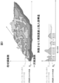
- this is referred to as a characteristic X-ray intensity and unevenness correlation distribution chart, and a schematic diagram showing this is shown in FIG. A method for identifying the morphology of the film using the information obtained from this figure will be described.
- the areas A0 to A5 are determined in the observation area by the following procedure.
- A0 In the schematic view of the characteristic X-ray intensity and unevenness correlation distribution chart shown in FIG. 4, all the observation areas in the outermost frame are indicated by A0.
- the region filled with dark gray is a region higher than the median value H0 of the unevenness.
- the inside of the frame indicated by the light gray line is a region (inserted oxide region) A1 which is 0.2 ⁇ m higher than H0. Outside the frame indicated by the light gray line is the surface oxide layer region A2.
- the Al (aluminum) concentrated region is represented by A3 (shown by dots) and A5 (shown by black).
- A5 indicates an Al (aluminum) concentrated region existing in the inlaid oxide region (A1).
- the area A4 (inside the frame of the dotted line) shows the Ca group element concentrated area described below.
- the area A0 is the entire observation area, that is, an area of at least 20 ⁇ m ⁇ 15 ⁇ m or more, and all the pixels of the characteristic X-ray and the unevenness correlation distribution map correspond to this area A0.
- A0 may be described as an “observation region”.
- the area A1 and the area A2 are divided based on the characteristic X-ray intensity and the unevenness correlation distribution chart.
- the primary coating is classified into two regions in the thickness direction based on the position H0 in the thickness direction of the steel sheet, the "inserted oxide layer (2)" and the "surface oxide layer (1)".
- Areas A1 and A2 are areas where this classification is developed on the projection plane.
- H0 is the median value of the height data of the characteristic X-ray intensity and the unevenness correlation distribution chart. Here, it is an arithmetic average value of two height values of 200 ⁇ 150 close to the center.
- the region having a height of H0+0.2 ⁇ m or more is the “inserted oxide layer (2)”, and the one seen on the projection plane is the “inserted oxide layer region” A1.
- the area having a height of less than H0+0.2 ⁇ m is the “surface oxide layer (1)”, and is the “surface oxide layer area” A2 on the projection plane.
- the areas A3 and A4 are divided based on the characteristic X-ray intensity and the unevenness correlation distribution chart.
- the maximum value of the characteristic X-ray intensity of Al (aluminum) is specified, and the region in which the intensity is 20% or more of the maximum value of the characteristic X-ray intensity of Al is A3. is there.
- the region A3 will be referred to as "Al concentrated region”.
- the characteristic X-ray intensities of Ca, Sr, and Ba are specified, and the characteristic X-ray intensity of Ca that is 20% or more of the maximum value of the characteristic X-ray intensity of Ca is obtained.
- A4 is the area including the area where is obtained. That is, the region A4 is a region in which the characteristic X-ray intensity of any element of Ca, Sr, and Ba is 20% or more of the maximum characteristic X-ray intensity of the element.
- A4 is described as "Ca group element concentrated region”.
- A5 a region existing in the inlaid oxide layer region A1 and being an Al (aluminum) concentrated region A3 is specified as A5.
- the area A5 will be referred to as an “inserted Al (aluminum) area”.
- the number density (number/ ⁇ m 2 ) of the number of each region, the total area ( ⁇ m 2 ) of each region, and the position (height ( ⁇ m)) in the plate thickness direction of each region are specified. Areas are required for the areas A0, A1, A3, and A5, and the respective areas are S0, S1, S3, and S5. It is A3 and A4 that the number density of the number of regions is required. The number densities of the numbers of A3 and A4 areas are D3 and D4, respectively.
- one region is defined as a region in which pixels are vertically or horizontally contiguous in pixel units, and a region composed of four or more pixels is specified to calculate the number.
- D3 is the area of the observation area A0 (that is, the total observation area S0, which is the total number of areas measured by regarding the area A3 in which the pixels are continuous in pixels as one area). ) Divided by. D4 is calculated by the same method.
- the region A5 is required to have a position in the plate thickness direction.
- the position of the area A5 is H5.
- This position is specified with reference to H0, which is the boundary between the surface oxide layer (1) and the fitting oxide layer (2). Specifically, it is a value obtained by subtracting H0 from the average value of the heights of all the pixels in the area A5. Since the area A5 exists at a position where the height in the characteristic X-ray intensity and the unevenness correlation distribution diagram is H0+0.2 ⁇ m or more, the average value of the height of the pixels in the area A5 is always H0+0.2 ⁇ m or more, and the result H5 has a value of 0.2 ⁇ m or more.
- the characteristic primary coating film of the present invention will be described below.
- the primary coating of the present invention contains Mg 2 SiO 4 as a main component, it has a great feature in the Al distribution in the vicinity of the interface between the primary coating and the base steel sheet.
- the characteristics of the intercalated oxide layer (2) will be described first, and then the characteristics of the entire primary coating will be described.
- the present invention is characterized in that D3, which is the number density of the Al concentrated region A3 near the interface, is D3: 0.015 to 0.150/ ⁇ m 2 . If D3 is out of this range, the effect of improving the coating adhesion to bending cannot be obtained.
- a region that is a fitting oxide layer region that is, a region that is a fitting oxide layer region A1 and is an Al (aluminum)-rich region A3 (fitting Al region A5) has a peripheral length L5 of
- the ratio to the observed area, L5/S0 is in the range of 0.020 to 0.500 ⁇ m/ ⁇ m 2 . If this ratio is less than 0.02 ⁇ m/ ⁇ m 2 , the effect of improving the coating adhesion to bending cannot be obtained. On the other hand, if it exceeds 0.500 ⁇ m/ ⁇ m 2 , the core loss characteristics deteriorate.
- the perimeter L5 is the total of the perimeters of the fitting Al region A5, and the perimeter of the fitting Al region A5 is the perimeter of consecutive pixels forming one fitting Al region A5. Furthermore, the position H5 in the plate thickness direction of the fitted Al region is H5: 0.4 to 4.0 ⁇ m. If this value is less than 0.4 ⁇ m, the effect of improving the coating adhesion to bending cannot be obtained. On the other hand, if it exceeds 4.0 ⁇ m, the embedded oxide is excessively elongated in the plate thickness direction, so that the circumferential length is reduced, the gas escape property is not improved, and point defects occur.
- Al is an element having a strong tendency to form an oxide
- Al is selectively oxidized on the surface of the steel sheet during finish annealing, and Al diffuses from the inside of the base steel sheet toward the surface.
- MgAl 2 O 4 the amount of Mg 2 SiO 4 is reduced, the amount thereof is decreased, and the linear expansion coefficient is increased.
- the thickness of the surface oxide layer (1) mainly composed of Mg 2 SiO 4 becomes nonuniform.
- the present invention has a structure in which the Al-based oxide is formed at the tip position of the inlaid oxide deeply penetrating the mother steel plate, thereby improving the magnetic properties and improving the adhesion of the coating film against bending. It seems that they have achieved both at the same time.
- the specified value representing this is H5, and in the present invention, H5 is 0.4 ⁇ m or more, that is, the inserted Al region is formed at a position separated from H0 by 0.4 ⁇ m or more to the steel plate inner side (the tip side of the inserted oxide).
- the above structure is achieved by setting the peripheral length L5 of the fitted Al region per observation area to be 0.02 ⁇ m or more.
- the fact that such an inserted Al region A5 is at the tip of the inserted oxide also leads to D3 being a numerical value within an appropriate range. That is, if the number density of the inserted Al regions A5 is small, D3 is low. Further, even if a situation occurs in which the density of the inlaid Al regions becomes excessively high temporarily, the distance between the adjacent inlaid Al regions A5 becomes short, so they are united as the primary coating grows. Finally, D3 is unlikely to be an excessively high value.
- Al diffused from the inside of the steel sheet will not reach the surface oxide layer (1), so that S5/S3 is inevitably high.
- the state of Al in the Al-concentrated region A3 is not specified at all, but considering that the main component of the primary coating is Mg 2 SiO 4 , Al in A3 is an oxide. It is reasonable to think that it exists as.
- the shape of the inlaid oxide layer (2) cannot be said to have a remarkable external characteristic, but the above-mentioned characteristic Al distribution of the inlaid oxide layer (2) is not so remarkable. Since the phenomenon in the tip region is utilized, it is difficult to form a characteristic Al distribution unless the inlaid oxide itself exists. Therefore, the area ratio of the embedded oxide layer region on the projection plane is defined as the presence of the embedded oxide.
- the specified numerical range itself is such that it can be observed even in grain-oriented electrical steel sheets with excellent coating adhesion in general shearing, but it is important as a necessary condition for obtaining a characteristic Al distribution. Can also be said.
- the primary coating of the present invention contains forsterite (Mg 2 SiO 4 ) as a main component. More specifically, the primary coating contains 50-95 wt% Mg 2 SiO 4 .
- the balance is generally known oxides such as MgAl 2 O 4 and sulfides such as MnS.
- the primary coating of the present invention has a total Y group element content of 0.1 to 6.00 mass% and a total Ca group element content of 0.1 to 6.0% by mass relative to the content of Mg 2 SiO 4 in the primary coating film. It is preferably contained in an amount of up to 6.00 mass %.
- an annealing separator containing a Y group element in order to realize the above-mentioned Al oxidation state.
- the Y group element remains in the primary coating after the finish annealing.
- the total content of the Y group element in the primary coating is less than 0.1% by mass, the content of the Y group element in the annealing separator cannot be said to be sufficient, and the coating adhesion to bending is not improved. If it exceeds 6.00 mass %, the thickness of the inlaid oxide layer (2) becomes too thick, and the oxide hinders the domain wall movement during magnetization, so that the adverse effect on the magnetic properties becomes remarkable.
- an annealing separator containing a Ca group element in order to realize the above-described Al oxidation state, it is preferable to use an annealing separator containing a Ca group element.
- the Ca group element will remain in the primary coating after the finish annealing. If the total content of Ca group elements in the primary coating is less than 0.1% by mass, the content of Ca group elements in the annealing separator cannot be said to be sufficient, and the coating adhesion in bending cannot be improved. If it exceeds 6.00% by mass, the number density of the intruding oxide layer (2) becomes too high, and the intruding oxides adjacent to each other are united and integrated, so that not only the number density of the intruding oxide decreases as a result. Since it is not possible to obtain a characteristic Al distribution, it is not possible to improve the coating adhesion in bending.
- the content of Mg 2 SiO 4 in the primary coating is quantitatively analyzed by inductively coupled plasma mass spectrometry (ICP-MS) using the primary coating separated from the magnetic steel sheet by the method described above as a sample.
- the product of the obtained quantitative value (mass %) and the molecular weight of Mg 2 SiO 4 is divided by twice the atomic weight of Mg to obtain the content of Mg 2 SiO 4 .
- quantitative analysis is performed by the same method as described above, and the same calculation as above is performed for the obtained content value (mass %). Then, the contents of these elements were calculated.
- the obtained total content of Ca, Ba, and Sr was defined as "Ca group element content”
- the obtained total content of Y, La, and Ce was defined as "Y group element content”.
- the "number density of Ca group element concentrated regions A4" D4 on the projection plane is 0.005/ ⁇ m 2 or more.
- the number density D4 of the Ca group element-enriched region A4 in the primary coating defined here represents a form in which the Ca group element that has acted on the formation of the inlaid oxide during the formation of the primary coating remains in the primary coating.
- D4 is preferably 2.000/ ⁇ m 2 or less.
- An example of the method for manufacturing the grain-oriented electrical steel sheet according to the present invention will be described.
- An example of a method for producing a grain-oriented electrical steel sheet includes a steel making step, a hot rolling step, a hot rolled sheet annealing, a cold rolling step, a decarburizing annealing step, a finishing annealing step, a flattening annealing step, and a film baking. And a magnetic domain control step.
- each step will be described.
- molten steel is melted by a usual method such as a converter, and a well-known refining process and casting process are carried out to manufacture a slab having the following chemical composition.
- a well-known refining process and casting process are carried out to manufacture a slab having the following chemical composition.
- each element of the chemical composition of the slab is removed to some extent from the components in the steel in the finish annealing step described later.
- S, Al, N, etc. which function as inhibitors, are largely removed. Therefore, the chemical composition of the slab described here is different from the chemical composition of the steel plate of the final product.
- the C content in the slab is 0.1 mass% or less.
- the preferable upper limit of the C content in the slab is 0.092% by mass, more preferably 0.085% by mass.
- the C content is less than 0.005 mass%, the dispersed state of precipitates such as MnS, MnSe, and AlN and the steel grain structure after decarburization annealing cannot be uniformly obtained, and Goss after secondary recrystallization is not obtained.
- the azimuth integration degree may be deteriorated. Therefore, the lower limit of the C content in the slab is 0.005% by mass.
- a preferred lower limit of the C content in the slab is 0.02% by mass, more preferably 0.04% by mass.
- Si 2.5 to 4.5 mass%
- Si enhances the electric resistance of steel, but if it is present in excess, the cold workability deteriorates.
- the Si content in the slab is 2.5 to 4.5 mass %
- the Si content in the grain-oriented electrical steel sheet after the finish annealing step will be 2.5 to 4.5 mass %.
- the preferable upper limit of the Si content in the slab is 4.0% by mass, and the more preferable upper limit is 3.8% by mass.
- the preferable lower limit of the Si content in the slab is 2.6%, and the more preferable lower limit is 2.8% by mass.
- Mn 0.02 to 0.20 mass%
- Mn combines with S and Se to form a precipitate during the manufacturing process, and functions as an inhibitor. Mn further enhances the hot workability of steel.
- the Mn content in the slab is 0.02 to 0.20 mass %
- the Mn content in the grain-oriented electrical steel sheet after the finish annealing step is 0.05 to 0.20 mass %.
- the preferable upper limit of the Mn content in the slab is 0.13% by mass, and the more preferable upper limit is 0.10% by mass.
- a preferable lower limit of the Mn content in the slab is 0.03% by mass, and a more preferable lower limit thereof is 0.04% by mass.
- One or more elements selected from the group consisting of S and Se 0.005 to 0.070 mass% in total
- sulfur (S) and selenium (Se) combine with Mn to form MnS and MnSe. Both MnS and MnSe function as inhibitors necessary for suppressing grain growth during secondary recrystallization. If the total content of one or more elements selected from the group consisting of S and Se is less than 0.005% by mass, it is difficult to obtain the above effect. On the other hand, if the total content of one or more elements selected from the group consisting of S and Se exceeds 0.070 mass %, secondary recrystallization does not occur during the manufacturing process and the magnetic properties of the steel deteriorate. To do.
- the total content of one or more elements selected from the group consisting of S and Se is 0.005 to 0.070 mass %.
- a preferable lower limit of the total content of at least one selected from the group consisting of S and Se is 0.008% by mass, and more preferably 0.016% by mass.
- a preferable upper limit of the total content of one or more kinds selected from the group consisting of S and Se is 0.060% by mass, and more preferably 0.050% by mass.
- sol. Al 0.005 to 0.050 mass%
- AlN functions as an inhibitor.
- the Al content is 0.005 to 0.050 mass %.
- the preferable upper limit of the Al content is 0.040% by mass, and more preferably 0.035% by mass.
- the preferable lower limit of the Al content is 0.010% by mass, and more preferably 0.015% by mass.
- N 0.0030 to 0.0300 mass%
- nitrogen (N) combines with Al to form AlN that functions as an inhibitor. If the N content in the slab is less than 0.0030% by mass, the above effect cannot be obtained. On the other hand, if the N content in the slab exceeds 0.0300 mass %, AlN becomes coarse. In this case, AlN becomes difficult to function as an inhibitor, and secondary recrystallization may not occur. Therefore, the N content in the slab is 0.0030 to 0.0300 mass %.
- the preferable upper limit of the N content in the slab is 0.0200% by mass, more preferably 0.0150% by mass.
- the preferable lower limit of the N content in the slab is 0.0040 mass%, more preferably 0.0060 mass%.
- the balance of the chemical composition in the slab of the present invention consists of Fe and impurities.
- the impurities are those that are mixed in from the ore as a raw material, scrap, or the manufacturing environment when the slab is industrially manufactured, and are allowed within a range that does not adversely affect the slab of the present embodiment. Means something.
- the slab according to the present invention may further contain one or more kinds selected from the group consisting of Cu, Sn and Sb in total of 0.60% by mass or less in place of a part of Fe. All of these elements are arbitrary elements.
- One or more elements selected from the group consisting of Cu, Sn and Sb: 0 to 0.60 mass% in total Copper (Cu), tin (Sn) and antimony (Sb) are all optional elements and may not be contained.
- Cu, Sn and Sb all increase the magnetic flux density of the grain-oriented electrical steel sheet. If Cu, Sn, and Sb are contained in any amount, the above effect can be obtained to some extent. However, if the total content of Cu, Sn and Sb exceeds 0.6% by mass, it becomes difficult to form the internal oxide layer during decarburization annealing.
- the total content of one or more elements selected from the group consisting of Cu, Sn and Sb is 0 to 0.6% by mass.
- a preferable lower limit of the total content of one or more elements selected from the group consisting of Cu, Sn, and Sb is 0.005% by mass, and more preferably 0.007% by mass.
- the preferable upper limit of the total content of one or more elements selected from the group consisting of Cu, Sn and Sb is 0.50% by mass, and more preferably 0.45% by mass.
- the slab according to the present invention may further contain one or more selected from the group consisting of Bi, Te and Pb in total of 0.030 mass% or less in place of a part of Fe. All of these elements are arbitrary elements.
- One or more elements selected from the group consisting of Bi, Te and Pb: 0 to 0.030% in total Bismuth (Bi), tellurium (Te), and lead (Pb) are all optional elements, but they are noteworthy elements in the present invention from the following viewpoints. These elements increase the magnetic flux density of the grain-oriented electrical steel sheet.
- the lower limit value of the total content of one or more selected from the group consisting of Bi, Te and Pb is 0.0005%, and more preferably 0.001% by mass.
- the inlaid oxide layer (2) does not become thick and the coating adhesion of the primary coating deteriorates.
- the amount of addition has to be limited to about 0.005 mass% or less in order to secure the adhesion of the coating film, although it has the effect of increasing the magnetic flux density. Since the effect of the present invention improves the film adhesion by changing the structure of the oxide to be inserted, it is also particularly effective when a manufacturing method containing these elements is applied. When the present invention is applied, even if these elements are 0.010% by mass or more, and further 0.015% by mass or more, it becomes possible to secure good film adhesion. However, if it is contained in excess, the lowering of the adhesiveness cannot be avoided even with the effect of the present invention, so the upper limit is made 0.030 mass %. A preferable upper limit is 0.020%, and a more preferable upper limit is 0.015% by mass.
- Hot rolling process A slab having the above chemical composition is heated.
- the heating temperature of the slab is, for example, more than 1280°C to 1350°C.
- Hot rolling is performed on the heated slab to produce a hot rolled steel sheet.
- the hot-rolled steel sheet may be annealed if necessary.
- the conditions for hot-rolled sheet annealing are, for example, 900 to 1100° C. and 3 to 5 minutes.
- Cold rolling process In the cold rolling step, cold rolling is performed on the hot rolled steel sheet to produce a cold rolled steel sheet.
- Cold rolling is performed on the prepared hot-rolled steel sheet to produce a cold-rolled steel sheet which is the base steel sheet.
- Cold rolling may be carried out only once, or may be carried out plural times.
- intermediate annealing for the purpose of softening is performed, and then cold rolling is further performed.
- Cold rolling is performed once or a plurality of times to manufacture a cold rolled steel sheet having a product sheet thickness (sheet thickness as a product).
- the cold rolling rate in one or more times of cold rolling is 80% or more.
- the cold rolling rate (%) is defined as follows.
- Cold rolling rate (%) 1-plate thickness of cold rolled steel plate after the last cold rolling/plate thickness of hot rolled steel plate before the start of the first cold rolling ⁇ 100
- the preferable upper limit of the cold rolling rate is 95%. Further, before performing cold rolling on the hot rolled steel sheet, heat treatment may be performed on the hot rolled steel sheet, or pickling may be performed.
- Decarburization annealing is performed on the cold rolled steel sheet manufactured by the cold rolling step, and nitriding annealing is performed as necessary.
- the decarburization annealing is performed in a well-known wet atmosphere containing hydrogen and nitrogen.
- the decarburization annealing reduces the C concentration of the grain-oriented electrical steel sheet to 50 ppm or less, which can suppress the magnetic aging deterioration.
- Decarburization annealing further causes primary recrystallization in the steel sheet structure to release the processing strain introduced by the cold rolling process. Further, in the decarburization annealing step, an internal oxide layer containing SiO 2 as a main component is formed on the surface layer portion of the base steel sheet.
- the SiO 2 formed here reacts with MgO in the aqueous slurry containing the annealing separator applied subsequently during the finish annealing to form a primary coating whose morphology is controlled in the present invention.
- the annealing temperature in the decarburization annealing step is well known and is, for example, 750 to 950°C.
- the holding time at the annealing temperature is, for example, 1 to 5 minutes.
- the “annealing separating agent” refers to a substance formed on the surface of the above decarburized and annealed plate, which is subjected to finish annealing, to impart a seizure prevention function during finish annealing.
- the layer of the annealing separating agent formed on the surface of the decarburized annealing plate is referred to as "annealing separating agent layer”.
- an aqueous slurry containing a compound that constitutes the annealing separator is prepared.
- the aqueous slurry is prepared by adding the elements constituting the annealing separator described later as pure compounds to pure water and stirring.
- This slurry is applied to the surface of the above decarburized and annealed plate with a roll coater, a spray, or the like.
- the steel sheet coated with the slurry is inserted into a furnace kept at 400 to 1000° C. and kept for 10 to 90 seconds to dry the slurry on the surface.
- the temperature of the steel sheet itself rises only up to about 400° C. (no change in crystal structure such as recrystallization occurs).
- the annealing separator in the present invention and the state in which the annealing separator adheres to the surface of the steel sheet before finish annealing is called the annealing separator layer.
- the annealing separator finally covering the surface of the steel sheet before finish annealing is simply a mixture of various compounds used as the raw materials.
- finish annealing After the annealing separator is dried, finish annealing is performed.
- the annealing temperature is set to 1150 to 1250° C. and the base steel sheet (cold rolled steel sheet) is soaked.
- the soaking time is, for example, 15 to 30 hours.
- the atmosphere in the furnace during finish annealing is a known atmosphere.
- a part of the elements such as S, Al, and N that function as inhibitors are discharged out of the system. This process is sometimes called "purification (annealing)".
- a primary coating film containing Mg 2 SiO 4 as a main component is formed.
- the interface structure between the base steel sheet and the primary coating satisfies the requirements of the present invention, and the coating adhesion is improved.
- each element of the chemical composition of the hot rolled steel sheet is removed to some extent from the components in the steel by the decarburization annealing process and the finish annealing process.
- S, Al, N, etc. which function as inhibitors, are largely removed. Therefore, as compared with the chemical composition of the hot rolled steel sheet, the element content in the chemical composition of the base steel sheet of the grain-oriented electrical steel sheet is low as described above. If the above-mentioned manufacturing method is carried out using a hot rolled steel sheet having the above-mentioned chemical composition, a grain-oriented electrical steel sheet having the base material steel sheet having the above-mentioned chemical composition can be produced.
- an insulating film forming step may be further performed after the finish annealing step.
- baking is performed after applying an insulating coating agent mainly containing colloidal silica and phosphate on the surface of the grain-oriented electrical steel sheet after the temperature has been decreased during the finish annealing.
- an insulating coating which is a tension coating, is formed on the primary coating.
- the grain-oriented electrical steel sheet according to the present invention may be further subjected to a well-known magnetic domain subdivision treatment step after cold rolling, decarburization annealing, finish annealing step, insulating film forming step, or the like.
- the magnetic domain subdivision processing step the surface of the grain-oriented electrical steel sheet is irradiated with laser light having a magnetic domain subdivision effect, or a groove is formed on the surface. In this case, a grain-oriented electrical steel sheet having further excellent magnetic properties can be manufactured.
- the annealing separator of the present invention contains magnesium oxide (MgO) as a main component, and further comprises one or more elements (Y group elements) selected from the group consisting of Y, La, and Ce, and Ca, Sr, and Ba. It contains at least one element (Ca group element) selected from the group consisting of
- the annealing separator represents the ratio of the respective contents of Y, La, Ce, and Mg with respect to the content of MgO in the annealing separator by%, and represents [Y], [La], [Ce], and [Mg]. To do.
- the annealing separator has the following formula: (0.00562[Y]+0.00360[La]+0.00712[Ce])/0.0412[Mg] ⁇ 100(%): 0.20 to 1.60(%) Meet
- the respective coefficients of the above equation are obtained by assuming that Y, La, Ce, and Mg atoms present in the annealing separator are the stable oxides Y 2 O 3 , La 2 O 3 , Ce 2 O 3, and MgO, respectively. It is a coefficient for determining the abundance ratio that is considered to be contained, and is calculated as follows.
- (0.00562[Y]+0.00360[La]+0.00714[Ce])/0.0412[Mg] ⁇ 100 is the total calculated by converting the Y group element in the annealing separator as a stable oxide of each element. It is the ratio (percentage) of the above-mentioned content and MgO which is a main constituent substance in the annealing separator. In other words, it can also be said to be an index showing the magnitude of the influence of the Y group element on Mg in the oxide. Below, (0.00562[Y]+0.00360[La]+0.00714[Ce])/0.0412[Mg] ⁇ 100 is described as CY.
- the Y group element needs to be contained as a compound containing oxygen or a compound that is oxidized during finish annealing to be converted into a compound containing oxygen.
- the compound of the Y group element is, for example, an oxide, or a hydroxide, a carbonate, a sulfate or the like, which is partially or wholly converted into an oxide by the baking treatment (drying treatment) and finish annealing treatment described later.
- CY is 0.20 to 1.60%.
- the preferable lower limit of CY is 0.40%, more preferably 0.50%.
- the preferable upper limit is 1.40%, and more preferably 1.30%.
- the reason why the adhesion can be improved by controlling the content of the Y group element is not completely clear, but it is considered as follows. That is, the group Y element containing oxygen releases oxygen during finish annealing, maintains the oxygen partial pressure between the steel sheets of the coil during finish annealing, and develops the inlaid oxide layer (2) of the primary coating.
- the inlaid oxide layer is composed of Mg 2 SiO 4 formed by the reaction between MgO in the annealing separator and SiO 2 inside the base steel sheet. That is, in order to obtain a fitting structure with severe irregularities, it is necessary that SiO 2 which is an oxide in the steel sheet originally has severe irregularities.
- SiO 2 having such an interface has a high interfacial energy, it is unstable during finish annealing performed at a high temperature. Therefore, during finish annealing, SiO 2 formed inside the base material steel plate once decomposes and diffuses as Si and O in the base material steel plate, and is flattened. Furthermore, since the finish annealing is performed in a hydrogen atmosphere, the oxygen supply to the base steel sheet is small. In addition, the formation of an Al-based oxide, which is a more stable oxide than SiO 2 , reduces oxygen in the base steel sheet and makes SiO 2 more and more unstable.
- the decomposition of SiO 2 existing inside the base steel sheet becomes more remarkable than the depth formed by the Al-based oxide, and the SiO 2 becomes even more flattened through diffusion after decomposition, and the embedded oxide layer of the primary coating ( 2) is also flattened.
- the Y group element containing oxygen contained in the annealing separator releases oxygen, the oxygen partial pressure between the steel sheets of the coil during finish annealing becomes high. Due to the increase of the oxygen partial pressure between the steel sheets, oxygen is supplied into the base steel sheet, and the flattening of the internal oxide SiO 2 is delayed. Delaying the flattening of SiO 2 during finish annealing means that Mg 2 SiO 4 with severe irregularities is formed. Mg 2 SiO 4 is more stable than SiO 2 and its morphological change due to subsequent finish annealing is small. As a result, the irregularities of the inlaid oxide layer (2) of the primary coating become severe.
- the total content of Ca group elements contained in the annealing separator, the total content of Ca group elements contained as impurities in the MgO raw material powder contained in the annealing separator, and the ratio of these contents are defined. To do.
- the annealing separator represents the ratio of the respective contents of Ca, Sr, Ba and Mg to the content of MgO contained in the annealing separator in%, and represents [Ca], [Sr], [Ba], [Mg ]]
- the annealing separator is Ca, Sr, Ba, Mg content contained in the MgO raw powder with respect to the content of MgO in the MgO raw powder contained in the annealing separator is [Ca'], [Sr'], Let [Ba'] and [Mg'].
- the annealing separator has the following formula: (0.0249[Ca']+0.0114[Sr']+0.0073[Ba'])/0.0412[Mg'] ⁇ 100(%): 0.010 to 0.080(%) are satisfied.
- the total content of Ca group elements contained in the annealing separator and the total content of Ca group elements in the MgO raw material powder contained in the annealing separator are (Ca of MgO raw material powder contained in the annealing separator).
- the total content of group elements)/(total content of Ca group elements contained in the annealing separator): 0.020 to 0.200 is satisfied.
- each coefficient of the above formula is obtained by containing Ca, Ba, Sr, and Mg atoms present in the annealing separator or MgO raw material powder as the respective stable oxides CaO, BaO, SrO, and MgO.
- the coefficient calculated to compare the substance ratio can be calculated as follows.
- the total abundance ratio (0.0249[Ca]+0.0114[Sr]+0.0073[Ba])/0.0412[Mg] ⁇ 100(%) of Ca group elements contained in the annealing separator is CC
- the total abundance ratio of Ca group elements contained as impurities in the MgO raw material powder contained in the annealing separator (0.0249[Ca']+0.0114[Sr']+0.0073[Ba'])/0. 0412 [Mg'] x 100 (%) is described as CC'.
- the Ca group element is, for example, an oxide, or a hydroxide, a carbonate, or a sulfate, which is partially or wholly converted into an oxide by the baking treatment (drying treatment) and finish annealing treatment described later.
- the Ca group element diffuses in the primary coating during finish annealing, reaches the interface of the primary coating on the mother steel sheet side, and reacts with SiO 2 existing in the surface area of the mother steel sheet serving as the starting point for forming the primary coating to form an intrusion oxide.
- SiO 2 existing in the surface area of the mother steel sheet serving as the starting point for forming the primary coating to form an intrusion oxide.
- the base steel sheet is oxidized by decarburization annealing, and SiO 2 is formed in the surface layer region.
- This is the phenomenon itself in which Mg contained as an element diffuses toward the inner side of the base material steel sheet of SiO 2 and forms Mg 2 SiO 4 there.
- the Al-enriched region which is a feature of the present invention, is concentrated in the region due to Al diffused from the inside of the steel sheet reacting with Mg 2 SiO 4 .
- the Al-enriched region is also formed on the inner side of the mother steel sheet.
- the Ca group element has a function similar to that of Mg and forms a composite oxide of Ca group element oxide and Si oxide. It is considered that when this composite oxide reacts with Al, it concentrates Al in the reaction region.
- the Ca group element is faster, and when the Ca group element is present in the annealing separator, the composite oxide of SiO 2 and Ca group element is It increases the speed at which the inlaid oxide, which is formed in the inner region of the base steel sheet and advances into the steel sheet earlier than Mg 2 SiO 4 which is a composite oxide of SiO 2 and Mg, advances.
- the annealing separator containing the Ca group element not only increases the thickness of the inlaid oxide layer (2), but also increases the Al concentration position in the oxide, that is, H5. Become.
- the Ca group element becomes a compound containing an oxide or oxygen before the aqueous slurry is prepared or after the drying step and is dispersed in the annealing separator.
- the MgO raw material powder contains Ca group element as an impurity, the reactivity of the raw material powder MgO with SiO 2 is increased, and the MgO raw material powder functions as a relatively stable Ca group element source even in the latter stage of annealing.
- the primary coating film oxide can be stabilized by supplying a Ca group element source to.
- unstable SiO 2 can be replaced with a stable oxide film such as CaMgSi 2 O 6 at an early stage, and CaMgSi 2 O 6 is stabilized as a Ca group element source that does not limit the supply route of Mg.
- CaMgSi 2 O 6 is stabilized as a Ca group element source that does not limit the supply route of Mg.
- the form can be maintained until CaMgSi 2 O 6 is replaced with Mg 2 SiO 4 .
- the impurity Ca group element in MgO becomes excessively large, the amount of Ca supplied becomes excessive with respect to Mg, and for forming CaMgSi 2 O 6 necessary for maintaining the morphology of the primary coating in a complicated manner.
- the supply of Mg group elements decreases with respect to Ca group elements, and the formation of more stable MgSi 2 O 4 is delayed, so that the primary coating film undergoes a morphological change due to the thermal effect of annealing, and it becomes complicated to prevent point defects.
- the complicated primary film morphology cannot be maintained.
- point defects increase.
- the impurity Ca group element in MgO is excessively small, even if the Ca group element-containing additive added to the outside of the MgO raw material powder supplies sufficient Ca group element, the supply of Mg is relatively small.
- the more stable formation of MgSi 2 O 4 is delayed, and the point defects increase for the same reason.
- CC is less than 0.20, the above effect cannot be sufficiently obtained.
- the CC exceeds 1.80, the inlaid oxide layer may be excessively thick and the magnetic properties may be deteriorated.
- CC is 0.20 to 1.80, it is possible to improve the adhesion of the primary coating to the base material steel sheet while suppressing the deterioration of magnetic properties.
- CC' is less than 0.010 or more than 0.080, or CC'/CC is less than 0.020 or more than 0.200, point defects occur. Therefore, the CC′ range of the present invention is 0.010 to 0.080, and the CC′/CC range is 0.020 to 0.200.
- the annealing separator may further contain Ti, Zr, and Hf, if necessary.
- Ti group element one or more elements selected from the group consisting of Ti, Zr, and Hf may be described as “Ti group element”.
- the respective content ratios of Ti, Zr, Hf, and Mg with respect to the content of MgO contained in the annealing separator are represented by %, and are represented by [Ti], [Zr], [Hf], and [Mg].
- the annealing separator has the following formula: (0.0209[Ti]+0.0110[Zr]+0.0056[Hf])/0.0412[Mg] ⁇ 100(%) ⁇ 5.0(%) Meet
- each coefficient in the above formula is considered to contain Ti, Zr, and Hf present in the annealing separator as respective stable oxides TiO 2 , ZrO 2 , HfO 2, and MgO, and
- the coefficient calculated by the abundance ratio can be calculated as follows.
- the Ti group element in the annealing separator is the Ti group element in the annealing separator as a stable oxide of each element. It is the ratio (percentage) of the converted total content and MgO which is the main constituent in the annealing separator. In other words, it can also be said to be an index showing the magnitude of the influence of the Ti group element on Mg in the oxide.
- CT The Ti group element can be contained as a simple substance, an alloy, or a compound.
- the compound is, for example, sulfate, carbonate, hydroxide or the like.
- the Ti group element accelerates the reaction between MgO in the annealing separator and SiO 2 on the surface layer of the mother steel sheet formed by decarburization annealing during finish annealing, and promotes the formation of Mg 2 SiO 4 .
- the effect is saturated when CT exceeds 5.0, so 5.0 is made the upper limit.
- the annealing separator may contain an element whose known effect is known within a range not impairing the effect of the present invention.
- the annealing separating agent of the present invention contains the above-mentioned various elements, but they are present not only as elemental metals but also in the state of being mixed as various compounds.
- the present invention makes several provisions regarding this mixed situation.
- the average particle size of MgO is 0.1 to 2.8 ⁇ m.
- the average particle size of MgO is described as R1.
- R1 is less than 0.1 ⁇ m, MgO is too active, and after finishing annealing, seizure occurs between the plates of the coil, which deteriorates the properties as an annealing separator.
- R1 exceeds 2.8 ⁇ m, MgO is too inactive and the formation of the primary coating is delayed. Therefore, R1 is 0.1 to 2.8 ⁇ m.
- R1 and R2 are measured as follows.
- the raw material powder is measured by a laser diffraction/scattering method according to JIS Z8825 (2013) using a laser diffraction/scattering particle size distribution measuring device to obtain a volume-based particle size distribution. Further, this is converted into a particle size distribution based on the number of particles, and finally the average particle size based on the number of particles of each element is obtained.
- the particles containing Ca group element have an average particle size of 0.2 to 3.0 ⁇ m.
- the average particle size of particles containing a Ca group element is described as R2.
- R2 is less than 0.2 ⁇ m, Ca is too active, and the amount of Ca group element supplied to the primary coating film being formed becomes too large with respect to the amount of Mg supplied. Therefore, the reaction between Mg and Si is delayed, so that the formation of Mg 2 SiO 4 is rather delayed, and the adhesion of the primary coating is deteriorated.
- R2 exceeds 3.0 ⁇ m, the contact between MgO and SiO 2 is lost, so that the formation of Mg 2 SiO 4 is delayed and the adhesion of the primary coating is deteriorated. The method of measuring R2 will be described later.
- R1 and R2 defined in the present invention are values calculated on the basis of the number of particles.
- the average particle size of particles is often specified on a weight basis.
- the abundance ratio of particles within a specific particle size range is expressed as a ratio to the total weight.
- This weight-based average particle size cannot be a representative particle of the entire measurement target in the particle size distribution. For example, when the abundance ratio of coarse particles having a very low existence frequency slightly changes, the average particle size obtained is largely changed because the ratio of the coarse particles to the whole is large.
- the average particle size based on the number of particles defined in the present invention is based on the number of particles classified by size, if the number of particles of a specific size itself does not significantly change, the entire average particle size. Does not fluctuate significantly. That is, it is a value that reflects the particle size of particles having a high frequency of existence. In other words, this value has a strong correlation with the number of particles per unit volume.
- the effect of the present invention is controlled by the particle size of particles having a high frequency of occurrence, as described later, and the definition of the invention needs to be based on the average particle size based on the number of particles rather than the weight.
- the ratio of R2 to R1, that is, R2/R1 is within the range of 0.5 to 3.0. If R2/R1 is less than 0.5, the area ratio (S1/S0) of the inlaid oxide layer of the formed primary coating decreases, and the coating adhesion deteriorates. It is preferably 0.6 or more, and more preferably 0.8 or more. On the other hand, when R2/R1 exceeds 3.0, the area ratio (S1/S0) of the inlaid oxide of the formed primary coating decreases, and the coating adhesion deteriorates. It is preferably 2.6 or less, more preferably 2.2 or less.
- the supply of Mg is delayed in the region where only the Ca group element is in contact with the base steel sheet, so that the formation of the primary coating is delayed and the coating adhesion becomes poor. ..
- R2/R1 exceeds 3.0
- the Ca group element is dispersed less in MgO, so that the supply of Ca is delayed and the film adhesion of the formed primary film becomes poor. This means that the compound of the Ca group element is present between MgO and the steel sheet, which hinders the supply of Mg to the base steel sheet.
- the region where MgO is not in contact with the base steel sheet was a void if the compound of the Ca group element was not relatively fine, whereas the region where the compound of the Ca group element was relatively fine was the base material. It means changing to a region in which the supply of Mg to the steel sheet is hindered. As a result, in the region where MgO is in contact with the base steel plate and the region where it is not in contact, a significant difference is generated in the supply of Mg to the base steel plate, and the development of the primary coating becomes uneven. For this reason, the number density of the inlaid oxide becomes excessive, which becomes a factor of impeding the magnetic properties.
- the range in which the Ca group element can be supplied is reduced.
- the number density of the roots of the primary capsule becomes overcrowded in the place where the roots were supplied to.
- R2/R1 is in an appropriate range, the number density of compounds of the Ca group element dispersed in the annealing separator layer near the steel sheet increases, so rather than simply refining the compound of the Ca group element in a large amount.
- the supply of Ca, Sr, and Ba to the base steel sheet is made uniform, and as a result, the number density of the oxides to be inserted can be made uniform.
- the present invention defines the structure of the annealing separating agent layer in a state of being adhered to the surface of the steel sheet immediately after the finish annealing that has completed the annealing separating agent layer forming step.
- the number density of particles containing Ca group element in the Ca group enriched region existing in the region of 0 to 3.0 ⁇ m from the surface of the base material steel plate is 0.003 to 1.400/ It is ⁇ m 2 .
- this "number density of particles containing Ca group element in the Ca group enriched region” is described as D42. Controlling D42 within the above range improves the adhesion of the primary coating after finish annealing.
- the Ca group element contained in the annealing separator diffuses toward the base metal steel sheet side in the primary coating formed during the finish annealing, and the base metal steel sheet side of the primary coating, that is, the base metal side at the tip of the inserted oxide. As described above, it is considered that it forms a complex oxide with Al supplied from Al and acts so as to keep Al at the tip of the inserted oxide.
- the existence position of the Ca group element in the annealing separator layer is important, and the Ca group element is present on the base steel plate side, that is, in the region of 0 to 3.0 ⁇ m from the base steel plate surface. It is expedient for the thickened regions to be present. Further, as described above, the contact with the base steel sheet should not have a local bias, and the appropriate elemental dispersion state in the annealing separator for this purpose is due to the Ca group enriched region of the formed primary coating. It is considered to correlate with number density.
- D42 can be obtained by the following method.
- EDS-SEM analyzes the cross section obtained by CP-processing the annealing separating agent layer on the surface of the finished annealing steel sheet together with the finishing annealing steel sheet, and obtains the characteristic X-ray intensity distribution of the Ca group element. That is, the obtained characteristic X-ray intensity distribution map is a distribution map developed by projecting the information of the annealing separator on a plane parallel to the section in the plate thickness direction of the finish annealing steel plate.
- the characteristic X-ray intensity distribution map of the Ca group element is such that the boundary line between the steel plate surface and the annealing separating agent layer is as parallel as possible to the upper and lower pieces of the observation area, and the annealing separating agent layer is outside from the upper and lower ends of the observation field. Acquire with a field of view that does not overflow.
- the observation width direction of the steel sheet surface and the annealing separator layer, and the direction orthogonal to the observation width direction will be referred to as the observation height direction.
- the scanning step of the characteristic X-ray intensity distribution chart is the same in the observation width direction and the observation height direction, and the length is 0.1 ⁇ m or less.
- the length in the observation width direction is at least 20 ⁇ m or more.
- the characteristic X-ray intensity distribution map is decomposed into at least 200 pixels in the observation width direction.
- the characteristic X-ray intensities of Ca, Sr, and Ba are specified, and the characteristic X-ray intensity of Ca is 20% or more of the maximum value of the characteristic X-ray intensity of Ca.
- each pixel of this Ca group element enriched region is regarded as one region in which the pixels are vertically and horizontally continuous, and a region composed of four or more pixels is determined as a particle. Further, the coordinates of the center of gravity of each Ca group element enriched region in the observation region are obtained by image analysis. Then, the number N1 of particles having a center of gravity at a height of 3 ⁇ m from the surface of the base steel plate in the plate thickness direction is counted.
- An average value R2 of the circle equivalent diameter ( ⁇ ((area of 1 pixel) ⁇ (number of pixels of continuum) ⁇ 4/ ⁇ )) of the circle containing particles of Ca group element in the Ca group element concentrated region is calculated.
- the obtained N1, R2 obtained as described above, the length of the observation region and the observation width direction (the length of the observation region in the direction orthogonal to the plate thickness direction in the cross section (width of finish annealing steel plate) D42 N1/(3 ⁇ L ⁇ R2) (pieces/ ⁇ m 3 ) can be obtained from (direction observation region length)) L ⁇ m.
- the average particle size (for example, R1) of the compound dispersed in the annealing separating agent layer should be substantially the same as the average particle size obtained from the particle size distribution of the raw material powder of the simple substance added when preparing the aqueous slurry. I know. Therefore, the average particle size of each compound can be determined from the average particle size of the raw material powder by using the same method as the method of calculating R1. It is not necessary to limit the method for controlling the diameter of the compound particles containing each element in the raw material powder within a specific range, and it is possible to produce a powder having a desired particle size distribution by adjusting firing conditions and classification. It is not difficult for those skilled in the art of manufacturing raw material powder.
- the number density of the Ca group enriched region in the region of 0 to 3.0 ⁇ m from the base material steel plate surface in the annealing separator layer is appropriate. Can be controlled.
- the present invention relates to an annealing separating agent applied to a steel sheet before finish annealing and a primary coating formed by the same, which has an important role in forming a primary coating, and the base steel sheet does not need to be special. .. Therefore, in this example, the steel sheet was manufactured under constant conditions (hot rolling, cold rolling, annealing, etc.) that were not directly related to the effect of the invention.
- the common conditions of all the examples will be described, and then the results of examining the effects of the invention by changing the conditions related to the formation of the primary coating in the examples 1 and 2 will be described.
- Each slab of Table 1 heated at 1350°C was hot rolled to produce a hot rolled steel sheet having a plate thickness of 2.3 mm.
- molten steel No. 5 since the content of Si in the molten steel was too large, cracking occurred during hot rolling, and the hot rolled steel sheet could not be manufactured.
- the obtained hot rolled steel sheet was annealed, and then the hot rolled steel sheet was pickled.
- the hot-rolled sheet annealing was performed at 1100° C. for 5 minutes.
- the hot-rolled steel sheet after pickling was cold-rolled to produce a cold-rolled steel sheet having a thickness of 0.22 mm.
- the cold rolling rate is 90.4%.
- the cold-rolled steel sheet after the primary recrystallization annealing was applied to the front and back surfaces with an aqueous slurry prepared by mixing the annealing separator having the components shown in Table 2 with pure water.
- the decarburized annealed plate having the surface coated with the aqueous slurry was held in a furnace at 900° C. for 10 seconds to dry the aqueous slurry.
- a sample is taken from the steel sheet for finish annealing obtained in this step, and selected from the group consisting of Ca, Sr, and Ba in the Ca group element-enriched region existing in the region of 0 to 3.0 ⁇ m from the surface of the base material steel plate.
- the number density D42 of the particles containing at least one element is measured. The values are shown in Table 2.
- the content of Al or N is out of the range of an appropriate amount for forming a precipitate necessary for the secondary recrystallization, and the secondary recrystallization was not performed, so that the value of the magnetic flux density B8 was extremely deteriorated. It was outside the scope of the invention.
- the Cu content was too high, and the coating adhesion was extremely poor, which was outside the scope of the present invention.
- the Sn content was too high and the coating adhesion was inferior, which was outside the scope of the present invention.
- the total content of Bi, Te and Pb was too large, and the coating adhesion was inferior, which was outside the scope of the present invention.
- the composition of the base steel sheet becomes different from that of the slab that was the raw material, because decarburization annealing and finish annealing (purification annealing) were performed, similar to general grain-oriented electrical steel sheets.
- Table 3 shows the chemical composition of the base steel sheet of the produced grain-oriented electrical steel sheet.
- ⁇ Adhesion> A sample with a length of 60 mm and a width of 15 mm was sampled from the grain-oriented electrical steel sheet of each test number, and a bending test was performed with a curvature of 10 mm. The bending test was carried out by using a cylindrical mandrel bending tester and installing the sample so that the axial direction of the cylinder coincided with the width direction of the sample. The surface of the sample after the bending test was observed, and the total area of the region where the primary coating remained without peeling was determined. The primary coating residual rate was determined by the following formula.
- Primary coating residual rate total area of the area where the primary coating remains without peeling/area of sample surface ⁇ 100
- the primary coating residual rate of 90% or more was considered to be excellent in coating adhesion.
- ⁇ Spot defect> A sample having a length of 1 m and a width of 1 m was taken from the grain-oriented electrical steel sheet of each test number, and the occurrence frequency NP (Number Density of Pore) of dot defects was visually determined. If the number of point defects in 1 m 2 was 5 or less, it was determined that the point defects were suppressed.
- ⁇ Primary coating structure> A sample having a length of 300 mm and a width of 60 mm was taken from the grain-oriented electrical steel sheet of each test number in the rolling direction and subjected to constant-potential electrolysis in an electrolytic solution so that only the base steel sheet was dissolved to peel off the primary coating, The structure and composition were investigated.
- the stripping method and the measuring method were according to the above-mentioned means, and the electrolyte solution component used was a non-aqueous solvent system 10% acetylacetone-1% tetramethylammonium chloride-methanol, and the amount of electrolysis was 80 C/cm 2 . Finally, the following values were obtained.
- ⁇ Annealing agent layer> Cut a sample from the steel sheet in a state of drying the aqueous slurry before finish annealing, observe the annealing separator layer according to the method described above, (10) Number density D42 of Ca group enriched region in the annealing separator layer Got
- ⁇ annealing separator> The following values were obtained from the raw material powder of the annealing separator of the aqueous slurry according to the above-mentioned means. (11) Y group element total abundance ratio CY(0.00562[Y]+0.00360[La]+0.00714[Ce])/0.0412[Mg] ⁇ 100(%) (12) Ca group element content CC (0.0249 [Ca] + 0.0114 [Sr] + 0.0073 [Ba])/0.0412 [Mg] x 100 (%) (13) Average particle size R1 of MgO (14) Average particle size R2 of Ca group element-containing particles Further, only the annealing separator MgO was separated to obtain the following values.
- Example 1 The aqueous slurry applied to the steel sheet after decarburization annealing was prepared by mixing MgO, a compound of Y group element-containing compound and a compound of Ca group element-containing water with each group element content as shown in Table 2. At this time, the abundance ratio (CY, CC) of the compound species and each group element was changed.
- the area ratio S1/S0 of the inlaid oxide layer is 0.15 or more
- the area S5/S3 that is the inlaid Al area A5 is 0.30 or more
- the distance H5 is 0.4 or more
- Al The number density D3 of the concentrated region was 0.020 or more, which was within the range of the present invention.
- the magnetic flux density B8 was 1.93T or more, and excellent magnetic characteristics were obtained.
- the residual rate of the primary coating was 90% or more, and the number of point defects NP was 5/m 2 or less, showing excellent primary coating characteristics.
- test number 26 R1 was too large and the supply of Mg to the primary coating was delayed. As a result, S1/S0, S5/S3, L5/S0, and H5 all fell below the standard value. As a result, the residual rate of the primary coating was 42% and the coating adhesion was inferior.
- test number 33 R1 and R2 were within the range, but R2/R1 exceeded 3.0. As a result, the residual rate of the primary coating was less than 90%, and the coating adhesion was poor.
- R1 and R2 were within the range, but R2/R1 was less than 0.3. As a result, five / m 2 or more point-like defect occurs, the point defect becomes inferior, and primary film residual ratio is below 90%, the coating adhesion becomes inferior.
- the annealing separator was within the range, but the Bi, Te, and Pb contents in the molten steel component exceeded 0.03%. As a result, the residual rate of the primary coating was less than 90%, and the coating adhesion was poor.
- Example 2 The aqueous slurry applied to the steel sheet after decarburization annealing was treated with MgO, a Ti group element-containing compound, a total Y group element-containing compound, and a Ca group element-containing compound so that each group element content was as shown in Table 5. Mixed and adjusted. At this time, the compound species and the abundance ratio of each group element (CY, CC, CT) were changed.
- Table 6 shows the results. When the residual rate of the primary coating was 90% or more, it was judged that the adhesion of the primary coating to the mother steel sheet was excellent. Other criteria also refer to Example 1. It can be seen from Table 6 that those satisfying the requirements of the present invention can obtain good characteristics.
- test number 54 the total abundance ratio CC of the Ca group elements was too large, and the morphology of the primary coating was excessively developed, so that D3 exceeded 0.150 pieces/ ⁇ m 2 . As a result, the iron loss W17/50 exceeded 0.75, and the magnetic properties were inferior.
- test number 60 R1 and R2 were within the range, but R2/R1 was less than 0.3. As a result, five / m 2 or more point-like defect occurs, the point defect becomes inferior, and primary film residual ratio is below 90%, the adhesion became inferior.
Landscapes
- Chemical & Material Sciences (AREA)
- Engineering & Computer Science (AREA)
- Materials Engineering (AREA)
- Organic Chemistry (AREA)
- Mechanical Engineering (AREA)
- Metallurgy (AREA)
- Physics & Mathematics (AREA)
- Thermal Sciences (AREA)
- Crystallography & Structural Chemistry (AREA)
- Manufacturing & Machinery (AREA)
- Electromagnetism (AREA)
- Ceramic Engineering (AREA)
- Dispersion Chemistry (AREA)
- Power Engineering (AREA)
- General Chemical & Material Sciences (AREA)
- Chemical Kinetics & Catalysis (AREA)
- Structural Engineering (AREA)
- Inorganic Chemistry (AREA)
- Manufacturing Of Steel Electrode Plates (AREA)
- Chemical Treatment Of Metals (AREA)
- Soft Magnetic Materials (AREA)
Abstract
Priority Applications (8)
| Application Number | Priority Date | Filing Date | Title |
|---|---|---|---|
| EP20738801.8A EP3910080A4 (fr) | 2019-01-08 | 2020-01-08 | Tôle en acier électromagnétique orienté ainsi que procédé de fabrication de celle-ci, tôle en acier pour recuit de finition ainsi que procédé de fabrication de celle-ci, et agent de séparation de recuit |
| US17/421,338 US20220081743A1 (en) | 2019-01-08 | 2020-01-08 | Grain-oriented electrical steel sheet, finish annealing-use steel sheet, annealing separator, method for manufacturing grain-oriented electrical steel sheet, and method for manufacturing finish annealing-use steel sheet |
| KR1020217019856A KR102550567B1 (ko) | 2019-01-08 | 2020-01-08 | 방향성 전자 강판, 마무리 어닐링용 강판, 어닐링 분리제, 방향성 전자 강판의 제조 방법 및 마무리 어닐링용 강판의 제조 방법 |
| BR112021012986-3A BR112021012986B1 (pt) | 2019-01-08 | 2020-01-08 | Chapa de aço elétrico de grão orientado |
| JP2020565182A JP7180691B2 (ja) | 2019-01-08 | 2020-01-08 | 方向性電磁鋼板、仕上焼鈍用鋼板、焼鈍分離剤、方向性電磁鋼板の製造方法、及び仕上焼鈍用鋼板の製造方法 |
| CN202080007025.8A CN113195751B (zh) | 2019-01-08 | 2020-01-08 | 方向性电磁钢板、成品退火用钢板、退火分离剂、方向性电磁钢板的制造方法及成品退火用钢板的制造方法 |
| US17/901,936 US12454735B2 (en) | 2019-01-08 | 2022-09-02 | Grain-oriented electrical steel sheet, finish annealing-use steel sheet, annealing separator, method for manufacturing grain-oriented electrical steel sheet, and method for manufacturing finish annealing-use steel sheet |
| US19/344,079 US20260028691A1 (en) | 2019-01-08 | 2025-09-29 | Grain-oriented electrical steel sheet, finish annealing-use steel sheet, annealing separator, method for manufacturing grain-oriented electrical steel sheet, and method for manufacturing finish annealing-use steel sheet |
Applications Claiming Priority (2)
| Application Number | Priority Date | Filing Date | Title |
|---|---|---|---|
| JP2019001158 | 2019-01-08 | ||
| JP2019-001158 | 2019-01-08 |
Related Child Applications (2)
| Application Number | Title | Priority Date | Filing Date |
|---|---|---|---|
| US17/421,338 A-371-Of-International US20220081743A1 (en) | 2019-01-08 | 2020-01-08 | Grain-oriented electrical steel sheet, finish annealing-use steel sheet, annealing separator, method for manufacturing grain-oriented electrical steel sheet, and method for manufacturing finish annealing-use steel sheet |
| US17/901,936 Continuation-In-Part US12454735B2 (en) | 2019-01-08 | 2022-09-02 | Grain-oriented electrical steel sheet, finish annealing-use steel sheet, annealing separator, method for manufacturing grain-oriented electrical steel sheet, and method for manufacturing finish annealing-use steel sheet |
Publications (1)
| Publication Number | Publication Date |
|---|---|
| WO2020145313A1 true WO2020145313A1 (fr) | 2020-07-16 |
Family
ID=71521630
Family Applications (1)
| Application Number | Title | Priority Date | Filing Date |
|---|---|---|---|
| PCT/JP2020/000337 Ceased WO2020145313A1 (fr) | 2019-01-08 | 2020-01-08 | Tôle en acier électromagnétique orienté ainsi que procédé de fabrication de celle-ci, tôle en acier pour recuit de finition ainsi que procédé de fabrication de celle-ci, et agent de séparation de recuit |
Country Status (6)
| Country | Link |
|---|---|
| US (1) | US20220081743A1 (fr) |
| EP (1) | EP3910080A4 (fr) |
| JP (1) | JP7180691B2 (fr) |
| KR (1) | KR102550567B1 (fr) |
| CN (1) | CN113195751B (fr) |
| WO (1) | WO2020145313A1 (fr) |
Citations (9)
| Publication number | Priority date | Publication date | Assignee | Title |
|---|---|---|---|---|
| JPH0688171A (ja) | 1992-09-09 | 1994-03-29 | Nippon Steel Corp | 超高磁束密度一方向性電磁鋼板の製造方法 |
| JPH06220539A (ja) * | 1993-01-21 | 1994-08-09 | Nippon Steel Corp | 磁区細分化一方向性電磁鋼板の製造法 |
| JPH08269552A (ja) | 1995-03-28 | 1996-10-15 | Nippon Steel Corp | 超高磁束密度一方向性電磁鋼板の製造方法 |
| JP2005290446A (ja) | 2004-03-31 | 2005-10-20 | Jfe Steel Kk | 磁気特性および被膜特性に優れる方向性電磁鋼板の製造方法 |
| WO2006126660A1 (fr) * | 2005-05-23 | 2006-11-30 | Nippon Steel Corporation | Feuille d'acier electromagnetique a grain oriente presentant une excellente adherence a une pellicule et son procede de production |
| WO2008062853A1 (fr) * | 2006-11-22 | 2008-05-29 | Nippon Steel Corporation | Feuille d'acier électromagnétique à orientation unidirectionnelle de grains, ayant une excellente adhésion de film, et son procédé de fabrication |
| JP2008127634A (ja) | 2006-11-21 | 2008-06-05 | Nippon Steel Corp | 一方向性電磁鋼板の製造方法 |
| JP2017133072A (ja) * | 2016-01-28 | 2017-08-03 | 新日鐵住金株式会社 | 皮膜密着性及び耐錆性の優れた一方向性電磁鋼板、一方向性電磁鋼板用原板及びそれらの製造方法 |
| JP2018066061A (ja) * | 2016-10-18 | 2018-04-26 | Jfeスチール株式会社 | 方向性電磁鋼板およびその製造方法 |
Family Cites Families (9)
| Publication number | Priority date | Publication date | Assignee | Title |
|---|---|---|---|---|
| JPH0619113B2 (ja) * | 1987-04-07 | 1994-03-16 | 川崎製鉄株式会社 | 鉄損の極めて低い方向性電磁鋼板の製造方法 |
| JP2005264280A (ja) * | 2004-03-22 | 2005-09-29 | Jfe Steel Kk | 打ち抜き性及び耐被膜剥離性に優れた方向性電磁鋼板及びその製造方法 |
| JP5360272B2 (ja) * | 2011-08-18 | 2013-12-04 | Jfeスチール株式会社 | 方向性電磁鋼板の製造方法 |
| CN103857827B (zh) * | 2011-10-04 | 2016-01-20 | 杰富意钢铁株式会社 | 取向性电磁钢板用退火分离剂 |
| KR101677883B1 (ko) * | 2013-09-19 | 2016-11-18 | 제이에프이 스틸 가부시키가이샤 | 방향성 전기 강판 및 그 제조 방법 |
| WO2016105053A1 (fr) * | 2014-12-24 | 2016-06-30 | 주식회사 포스코 | Tôle magnétique à gains orientés et son procédé de production |
| KR101693516B1 (ko) * | 2014-12-24 | 2017-01-06 | 주식회사 포스코 | 방향성 전기강판 및 그 제조방법 |
| WO2018116831A1 (fr) * | 2016-12-21 | 2018-06-28 | Jfeスチール株式会社 | Tôle d'acier électrique à grains orientés et procédé de production d'une tôle d'acier électrique à grains orientés |
| KR101906962B1 (ko) | 2016-12-22 | 2018-10-11 | 주식회사 포스코 | 방향성 전기강판용 소둔 분리제 조성물, 방향성 전기강판 및 방향성 전기강판의 제조방법 |
-
2020
- 2020-01-08 EP EP20738801.8A patent/EP3910080A4/fr active Pending
- 2020-01-08 CN CN202080007025.8A patent/CN113195751B/zh active Active
- 2020-01-08 US US17/421,338 patent/US20220081743A1/en not_active Abandoned
- 2020-01-08 KR KR1020217019856A patent/KR102550567B1/ko active Active
- 2020-01-08 WO PCT/JP2020/000337 patent/WO2020145313A1/fr not_active Ceased
- 2020-01-08 JP JP2020565182A patent/JP7180691B2/ja active Active
Patent Citations (10)
| Publication number | Priority date | Publication date | Assignee | Title |
|---|---|---|---|---|
| JPH0688171A (ja) | 1992-09-09 | 1994-03-29 | Nippon Steel Corp | 超高磁束密度一方向性電磁鋼板の製造方法 |
| JPH06220539A (ja) * | 1993-01-21 | 1994-08-09 | Nippon Steel Corp | 磁区細分化一方向性電磁鋼板の製造法 |
| JPH08269552A (ja) | 1995-03-28 | 1996-10-15 | Nippon Steel Corp | 超高磁束密度一方向性電磁鋼板の製造方法 |
| JP2005290446A (ja) | 2004-03-31 | 2005-10-20 | Jfe Steel Kk | 磁気特性および被膜特性に優れる方向性電磁鋼板の製造方法 |
| WO2006126660A1 (fr) * | 2005-05-23 | 2006-11-30 | Nippon Steel Corporation | Feuille d'acier electromagnetique a grain oriente presentant une excellente adherence a une pellicule et son procede de production |
| JP2012214902A (ja) | 2005-05-23 | 2012-11-08 | Nippon Steel Corp | 被膜密着性に優れる方向性電磁鋼板およびその製造方法 |
| JP2008127634A (ja) | 2006-11-21 | 2008-06-05 | Nippon Steel Corp | 一方向性電磁鋼板の製造方法 |
| WO2008062853A1 (fr) * | 2006-11-22 | 2008-05-29 | Nippon Steel Corporation | Feuille d'acier électromagnétique à orientation unidirectionnelle de grains, ayant une excellente adhésion de film, et son procédé de fabrication |
| JP2017133072A (ja) * | 2016-01-28 | 2017-08-03 | 新日鐵住金株式会社 | 皮膜密着性及び耐錆性の優れた一方向性電磁鋼板、一方向性電磁鋼板用原板及びそれらの製造方法 |
| JP2018066061A (ja) * | 2016-10-18 | 2018-04-26 | Jfeスチール株式会社 | 方向性電磁鋼板およびその製造方法 |
Non-Patent Citations (1)
| Title |
|---|
| See also references of EP3910080A4 |
Also Published As
| Publication number | Publication date |
|---|---|
| US20220081743A1 (en) | 2022-03-17 |
| EP3910080A4 (fr) | 2022-09-28 |
| EP3910080A1 (fr) | 2021-11-17 |
| BR112021012986A2 (pt) | 2021-09-14 |
| KR20210094625A (ko) | 2021-07-29 |
| CN113195751A (zh) | 2021-07-30 |
| CN113195751B (zh) | 2023-01-10 |
| KR102550567B1 (ko) | 2023-07-04 |
| JPWO2020145313A1 (ja) | 2021-11-25 |
| JP7180691B2 (ja) | 2022-11-30 |
Similar Documents
| Publication | Publication Date | Title |
|---|---|---|
| KR101165430B1 (ko) | 피막 밀착성이 우수한 일방향성 전자 강판 및 그 제조법 | |
| KR101453235B1 (ko) | 방향성 전자기 강판 및 그 제조 방법 | |
| JP6624180B2 (ja) | 方向性電磁鋼板およびその製造方法 | |
| JP7837135B2 (ja) | 方向性電磁鋼板、および方向性電磁鋼板の製造方法、ならびに焼鈍分離剤 | |
| CN113260718B (zh) | 方向性电磁钢板、方向性电磁钢板的制造方法及方向性电磁钢板的制造中利用的退火分离剂 | |
| JP2020111816A (ja) | 方向性電磁鋼板及びその製造方法 | |
| JP7184098B2 (ja) | 方向性電磁鋼板、焼鈍分離剤、及び方向性電磁鋼板の製造方法 | |
| JP2021123768A (ja) | 方向性電磁鋼板の製造方法および方向性電磁鋼板、ならびに焼鈍分離剤 | |
| JP7180691B2 (ja) | 方向性電磁鋼板、仕上焼鈍用鋼板、焼鈍分離剤、方向性電磁鋼板の製造方法、及び仕上焼鈍用鋼板の製造方法 | |
| US12454735B2 (en) | Grain-oriented electrical steel sheet, finish annealing-use steel sheet, annealing separator, method for manufacturing grain-oriented electrical steel sheet, and method for manufacturing finish annealing-use steel sheet | |
| JP7205555B2 (ja) | 方向性電磁鋼板およびその製造方法、ならびに焼鈍分離剤 | |
| RU2777398C1 (ru) | Лист электротехнической стали с ориентированной зеренной структурой, стальной лист, используемый для финишного отжига, отжиговый сепаратор, способ изготовления листа электротехнической стали с ориентированной зеренной структурой и способ изготовления стального листа, используемого для финишного отжига | |
| RU2792912C2 (ru) | Лист электротехнической стали с ориентированной зеренной структурой, стальной лист, используемый для финишного отжига, отжиговый сепаратор, способ изготовления листа электротехнической стали с ориентированной зеренной структурой и способ изготовления стального листа, используемого для финишного отжига | |
| JP2021123767A (ja) | 方向性電磁鋼板の製造方法および方向性電磁鋼板、ならびに焼鈍分離剤 | |
| RU2773042C1 (ru) | Лист анизотропной электротехнической стали, сепаратор отжига и способ производства листа анизотропной электротехнической стали | |
| JP7568894B2 (ja) | 方向性電磁鋼板、仕上焼鈍用鋼板、焼鈍分離剤、方向性電磁鋼板の製造方法、及び仕上焼鈍用鋼板の製造方法 | |
| CN112771183B (zh) | 方向性电磁钢板、方向性电磁钢板的制造方法及方向性电磁钢板的制造中利用的退火分离剂 | |
| WO2020145321A1 (fr) | Tôle en acier électromagnétique orienté ainsi que procédé de fabrication de celle-ci, et agent de séparation de recuit mis en œuvre dans la fabrication de cette tôle en acier | |
| BR122025011248A2 (pt) | Chapa de aço de uso de recozimento final para a fabricação de chapa de aço elétrico de grão orientado, separador de recozimento, e, métodos para fabricar chapa de aço elétrico de grão orientado e para fabricar chapa de aço para uso em recozimento final | |
| WO2021085421A1 (fr) | Tôle d'acier électromagnétique à grains orientés et son procédé de fabrication |
Legal Events
| Date | Code | Title | Description |
|---|---|---|---|
| 121 | Ep: the epo has been informed by wipo that ep was designated in this application |
Ref document number: 20738801 Country of ref document: EP Kind code of ref document: A1 |
|
| ENP | Entry into the national phase |
Ref document number: 2020565182 Country of ref document: JP Kind code of ref document: A |
|
| ENP | Entry into the national phase |
Ref document number: 20217019856 Country of ref document: KR Kind code of ref document: A |
|
| NENP | Non-entry into the national phase |
Ref country code: DE |
|
| REG | Reference to national code |
Ref country code: BR Ref legal event code: B01A Ref document number: 112021012986 Country of ref document: BR |
|
| ENP | Entry into the national phase |
Ref document number: 2020738801 Country of ref document: EP Effective date: 20210809 |
|
| ENP | Entry into the national phase |
Ref document number: 112021012986 Country of ref document: BR Kind code of ref document: A2 Effective date: 20210630 |