WO2020162500A1 - Systeme d'alimentation par vaporisation solide d'un compose halogene metallique pour former un film mince - Google Patents
Systeme d'alimentation par vaporisation solide d'un compose halogene metallique pour former un film mince Download PDFInfo
- Publication number
- WO2020162500A1 WO2020162500A1 PCT/JP2020/004368 JP2020004368W WO2020162500A1 WO 2020162500 A1 WO2020162500 A1 WO 2020162500A1 JP 2020004368 W JP2020004368 W JP 2020004368W WO 2020162500 A1 WO2020162500 A1 WO 2020162500A1
- Authority
- WO
- WIPO (PCT)
- Prior art keywords
- container
- supply system
- container body
- raw material
- wall
- Prior art date
- Legal status (The legal status is an assumption and is not a legal conclusion. Google has not performed a legal analysis and makes no representation as to the accuracy of the status listed.)
- Ceased
Links
Images


Classifications
-
- C—CHEMISTRY; METALLURGY
- C23—COATING METALLIC MATERIAL; COATING MATERIAL WITH METALLIC MATERIAL; CHEMICAL SURFACE TREATMENT; DIFFUSION TREATMENT OF METALLIC MATERIAL; COATING BY VACUUM EVAPORATION, BY SPUTTERING, BY ION IMPLANTATION OR BY CHEMICAL VAPOUR DEPOSITION, IN GENERAL; INHIBITING CORROSION OF METALLIC MATERIAL OR INCRUSTATION IN GENERAL
- C23C—COATING METALLIC MATERIAL; COATING MATERIAL WITH METALLIC MATERIAL; SURFACE TREATMENT OF METALLIC MATERIAL BY DIFFUSION INTO THE SURFACE, BY CHEMICAL CONVERSION OR SUBSTITUTION; COATING BY VACUUM EVAPORATION, BY SPUTTERING, BY ION IMPLANTATION OR BY CHEMICAL VAPOUR DEPOSITION, IN GENERAL
- C23C16/00—Chemical coating by decomposition of gaseous compounds, without leaving reaction products of surface material in the coating, i.e. chemical vapour deposition [CVD] processes
- C23C16/22—Chemical coating by decomposition of gaseous compounds, without leaving reaction products of surface material in the coating, i.e. chemical vapour deposition [CVD] processes characterised by the deposition of inorganic material, other than metallic material
- C23C16/30—Deposition of compounds, mixtures or solid solutions, e.g. borides, carbides, nitrides
- C23C16/40—Oxides
- C23C16/405—Oxides of refractory metals or yttrium
-
- C—CHEMISTRY; METALLURGY
- C23—COATING METALLIC MATERIAL; COATING MATERIAL WITH METALLIC MATERIAL; CHEMICAL SURFACE TREATMENT; DIFFUSION TREATMENT OF METALLIC MATERIAL; COATING BY VACUUM EVAPORATION, BY SPUTTERING, BY ION IMPLANTATION OR BY CHEMICAL VAPOUR DEPOSITION, IN GENERAL; INHIBITING CORROSION OF METALLIC MATERIAL OR INCRUSTATION IN GENERAL
- C23C—COATING METALLIC MATERIAL; COATING MATERIAL WITH METALLIC MATERIAL; SURFACE TREATMENT OF METALLIC MATERIAL BY DIFFUSION INTO THE SURFACE, BY CHEMICAL CONVERSION OR SUBSTITUTION; COATING BY VACUUM EVAPORATION, BY SPUTTERING, BY ION IMPLANTATION OR BY CHEMICAL VAPOUR DEPOSITION, IN GENERAL
- C23C16/00—Chemical coating by decomposition of gaseous compounds, without leaving reaction products of surface material in the coating, i.e. chemical vapour deposition [CVD] processes
- C23C16/22—Chemical coating by decomposition of gaseous compounds, without leaving reaction products of surface material in the coating, i.e. chemical vapour deposition [CVD] processes characterised by the deposition of inorganic material, other than metallic material
-
- C—CHEMISTRY; METALLURGY
- C23—COATING METALLIC MATERIAL; COATING MATERIAL WITH METALLIC MATERIAL; CHEMICAL SURFACE TREATMENT; DIFFUSION TREATMENT OF METALLIC MATERIAL; COATING BY VACUUM EVAPORATION, BY SPUTTERING, BY ION IMPLANTATION OR BY CHEMICAL VAPOUR DEPOSITION, IN GENERAL; INHIBITING CORROSION OF METALLIC MATERIAL OR INCRUSTATION IN GENERAL
- C23C—COATING METALLIC MATERIAL; COATING MATERIAL WITH METALLIC MATERIAL; SURFACE TREATMENT OF METALLIC MATERIAL BY DIFFUSION INTO THE SURFACE, BY CHEMICAL CONVERSION OR SUBSTITUTION; COATING BY VACUUM EVAPORATION, BY SPUTTERING, BY ION IMPLANTATION OR BY CHEMICAL VAPOUR DEPOSITION, IN GENERAL
- C23C16/00—Chemical coating by decomposition of gaseous compounds, without leaving reaction products of surface material in the coating, i.e. chemical vapour deposition [CVD] processes
- C23C16/22—Chemical coating by decomposition of gaseous compounds, without leaving reaction products of surface material in the coating, i.e. chemical vapour deposition [CVD] processes characterised by the deposition of inorganic material, other than metallic material
- C23C16/30—Deposition of compounds, mixtures or solid solutions, e.g. borides, carbides, nitrides
- C23C16/34—Nitrides
-
- C—CHEMISTRY; METALLURGY
- C23—COATING METALLIC MATERIAL; COATING MATERIAL WITH METALLIC MATERIAL; CHEMICAL SURFACE TREATMENT; DIFFUSION TREATMENT OF METALLIC MATERIAL; COATING BY VACUUM EVAPORATION, BY SPUTTERING, BY ION IMPLANTATION OR BY CHEMICAL VAPOUR DEPOSITION, IN GENERAL; INHIBITING CORROSION OF METALLIC MATERIAL OR INCRUSTATION IN GENERAL
- C23C—COATING METALLIC MATERIAL; COATING MATERIAL WITH METALLIC MATERIAL; SURFACE TREATMENT OF METALLIC MATERIAL BY DIFFUSION INTO THE SURFACE, BY CHEMICAL CONVERSION OR SUBSTITUTION; COATING BY VACUUM EVAPORATION, BY SPUTTERING, BY ION IMPLANTATION OR BY CHEMICAL VAPOUR DEPOSITION, IN GENERAL
- C23C16/00—Chemical coating by decomposition of gaseous compounds, without leaving reaction products of surface material in the coating, i.e. chemical vapour deposition [CVD] processes
- C23C16/22—Chemical coating by decomposition of gaseous compounds, without leaving reaction products of surface material in the coating, i.e. chemical vapour deposition [CVD] processes characterised by the deposition of inorganic material, other than metallic material
- C23C16/30—Deposition of compounds, mixtures or solid solutions, e.g. borides, carbides, nitrides
- C23C16/40—Oxides
-
- C—CHEMISTRY; METALLURGY
- C23—COATING METALLIC MATERIAL; COATING MATERIAL WITH METALLIC MATERIAL; CHEMICAL SURFACE TREATMENT; DIFFUSION TREATMENT OF METALLIC MATERIAL; COATING BY VACUUM EVAPORATION, BY SPUTTERING, BY ION IMPLANTATION OR BY CHEMICAL VAPOUR DEPOSITION, IN GENERAL; INHIBITING CORROSION OF METALLIC MATERIAL OR INCRUSTATION IN GENERAL
- C23C—COATING METALLIC MATERIAL; COATING MATERIAL WITH METALLIC MATERIAL; SURFACE TREATMENT OF METALLIC MATERIAL BY DIFFUSION INTO THE SURFACE, BY CHEMICAL CONVERSION OR SUBSTITUTION; COATING BY VACUUM EVAPORATION, BY SPUTTERING, BY ION IMPLANTATION OR BY CHEMICAL VAPOUR DEPOSITION, IN GENERAL
- C23C16/00—Chemical coating by decomposition of gaseous compounds, without leaving reaction products of surface material in the coating, i.e. chemical vapour deposition [CVD] processes
- C23C16/44—Chemical coating by decomposition of gaseous compounds, without leaving reaction products of surface material in the coating, i.e. chemical vapour deposition [CVD] processes characterised by the method of coating
- C23C16/4401—Means for minimising impurities, e.g. dust, moisture or residual gas, in the reaction chamber
- C23C16/4402—Reduction of impurities in the source gas
-
- C—CHEMISTRY; METALLURGY
- C23—COATING METALLIC MATERIAL; COATING MATERIAL WITH METALLIC MATERIAL; CHEMICAL SURFACE TREATMENT; DIFFUSION TREATMENT OF METALLIC MATERIAL; COATING BY VACUUM EVAPORATION, BY SPUTTERING, BY ION IMPLANTATION OR BY CHEMICAL VAPOUR DEPOSITION, IN GENERAL; INHIBITING CORROSION OF METALLIC MATERIAL OR INCRUSTATION IN GENERAL
- C23C—COATING METALLIC MATERIAL; COATING MATERIAL WITH METALLIC MATERIAL; SURFACE TREATMENT OF METALLIC MATERIAL BY DIFFUSION INTO THE SURFACE, BY CHEMICAL CONVERSION OR SUBSTITUTION; COATING BY VACUUM EVAPORATION, BY SPUTTERING, BY ION IMPLANTATION OR BY CHEMICAL VAPOUR DEPOSITION, IN GENERAL
- C23C16/00—Chemical coating by decomposition of gaseous compounds, without leaving reaction products of surface material in the coating, i.e. chemical vapour deposition [CVD] processes
- C23C16/44—Chemical coating by decomposition of gaseous compounds, without leaving reaction products of surface material in the coating, i.e. chemical vapour deposition [CVD] processes characterised by the method of coating
- C23C16/4401—Means for minimising impurities, e.g. dust, moisture or residual gas, in the reaction chamber
- C23C16/4404—Coatings or surface treatment on the inside of the reaction chamber or on parts thereof
-
- C—CHEMISTRY; METALLURGY
- C23—COATING METALLIC MATERIAL; COATING MATERIAL WITH METALLIC MATERIAL; CHEMICAL SURFACE TREATMENT; DIFFUSION TREATMENT OF METALLIC MATERIAL; COATING BY VACUUM EVAPORATION, BY SPUTTERING, BY ION IMPLANTATION OR BY CHEMICAL VAPOUR DEPOSITION, IN GENERAL; INHIBITING CORROSION OF METALLIC MATERIAL OR INCRUSTATION IN GENERAL
- C23C—COATING METALLIC MATERIAL; COATING MATERIAL WITH METALLIC MATERIAL; SURFACE TREATMENT OF METALLIC MATERIAL BY DIFFUSION INTO THE SURFACE, BY CHEMICAL CONVERSION OR SUBSTITUTION; COATING BY VACUUM EVAPORATION, BY SPUTTERING, BY ION IMPLANTATION OR BY CHEMICAL VAPOUR DEPOSITION, IN GENERAL
- C23C16/00—Chemical coating by decomposition of gaseous compounds, without leaving reaction products of surface material in the coating, i.e. chemical vapour deposition [CVD] processes
- C23C16/44—Chemical coating by decomposition of gaseous compounds, without leaving reaction products of surface material in the coating, i.e. chemical vapour deposition [CVD] processes characterised by the method of coating
- C23C16/448—Chemical coating by decomposition of gaseous compounds, without leaving reaction products of surface material in the coating, i.e. chemical vapour deposition [CVD] processes characterised by the method of coating characterised by the method used for generating reactive gas streams, e.g. by evaporation or sublimation of precursor materials
-
- C—CHEMISTRY; METALLURGY
- C23—COATING METALLIC MATERIAL; COATING MATERIAL WITH METALLIC MATERIAL; CHEMICAL SURFACE TREATMENT; DIFFUSION TREATMENT OF METALLIC MATERIAL; COATING BY VACUUM EVAPORATION, BY SPUTTERING, BY ION IMPLANTATION OR BY CHEMICAL VAPOUR DEPOSITION, IN GENERAL; INHIBITING CORROSION OF METALLIC MATERIAL OR INCRUSTATION IN GENERAL
- C23C—COATING METALLIC MATERIAL; COATING MATERIAL WITH METALLIC MATERIAL; SURFACE TREATMENT OF METALLIC MATERIAL BY DIFFUSION INTO THE SURFACE, BY CHEMICAL CONVERSION OR SUBSTITUTION; COATING BY VACUUM EVAPORATION, BY SPUTTERING, BY ION IMPLANTATION OR BY CHEMICAL VAPOUR DEPOSITION, IN GENERAL
- C23C16/00—Chemical coating by decomposition of gaseous compounds, without leaving reaction products of surface material in the coating, i.e. chemical vapour deposition [CVD] processes
- C23C16/44—Chemical coating by decomposition of gaseous compounds, without leaving reaction products of surface material in the coating, i.e. chemical vapour deposition [CVD] processes characterised by the method of coating
- C23C16/448—Chemical coating by decomposition of gaseous compounds, without leaving reaction products of surface material in the coating, i.e. chemical vapour deposition [CVD] processes characterised by the method of coating characterised by the method used for generating reactive gas streams, e.g. by evaporation or sublimation of precursor materials
- C23C16/4481—Chemical coating by decomposition of gaseous compounds, without leaving reaction products of surface material in the coating, i.e. chemical vapour deposition [CVD] processes characterised by the method of coating characterised by the method used for generating reactive gas streams, e.g. by evaporation or sublimation of precursor materials by evaporation using carrier gas in contact with the source material
-
- C—CHEMISTRY; METALLURGY
- C23—COATING METALLIC MATERIAL; COATING MATERIAL WITH METALLIC MATERIAL; CHEMICAL SURFACE TREATMENT; DIFFUSION TREATMENT OF METALLIC MATERIAL; COATING BY VACUUM EVAPORATION, BY SPUTTERING, BY ION IMPLANTATION OR BY CHEMICAL VAPOUR DEPOSITION, IN GENERAL; INHIBITING CORROSION OF METALLIC MATERIAL OR INCRUSTATION IN GENERAL
- C23C—COATING METALLIC MATERIAL; COATING MATERIAL WITH METALLIC MATERIAL; SURFACE TREATMENT OF METALLIC MATERIAL BY DIFFUSION INTO THE SURFACE, BY CHEMICAL CONVERSION OR SUBSTITUTION; COATING BY VACUUM EVAPORATION, BY SPUTTERING, BY ION IMPLANTATION OR BY CHEMICAL VAPOUR DEPOSITION, IN GENERAL
- C23C16/00—Chemical coating by decomposition of gaseous compounds, without leaving reaction products of surface material in the coating, i.e. chemical vapour deposition [CVD] processes
- C23C16/44—Chemical coating by decomposition of gaseous compounds, without leaving reaction products of surface material in the coating, i.e. chemical vapour deposition [CVD] processes characterised by the method of coating
- C23C16/448—Chemical coating by decomposition of gaseous compounds, without leaving reaction products of surface material in the coating, i.e. chemical vapour deposition [CVD] processes characterised by the method of coating characterised by the method used for generating reactive gas streams, e.g. by evaporation or sublimation of precursor materials
- C23C16/4481—Chemical coating by decomposition of gaseous compounds, without leaving reaction products of surface material in the coating, i.e. chemical vapour deposition [CVD] processes characterised by the method of coating characterised by the method used for generating reactive gas streams, e.g. by evaporation or sublimation of precursor materials by evaporation using carrier gas in contact with the source material
- C23C16/4483—Chemical coating by decomposition of gaseous compounds, without leaving reaction products of surface material in the coating, i.e. chemical vapour deposition [CVD] processes characterised by the method of coating characterised by the method used for generating reactive gas streams, e.g. by evaporation or sublimation of precursor materials by evaporation using carrier gas in contact with the source material using a porous body
-
- C—CHEMISTRY; METALLURGY
- C23—COATING METALLIC MATERIAL; COATING MATERIAL WITH METALLIC MATERIAL; CHEMICAL SURFACE TREATMENT; DIFFUSION TREATMENT OF METALLIC MATERIAL; COATING BY VACUUM EVAPORATION, BY SPUTTERING, BY ION IMPLANTATION OR BY CHEMICAL VAPOUR DEPOSITION, IN GENERAL; INHIBITING CORROSION OF METALLIC MATERIAL OR INCRUSTATION IN GENERAL
- C23C—COATING METALLIC MATERIAL; COATING MATERIAL WITH METALLIC MATERIAL; SURFACE TREATMENT OF METALLIC MATERIAL BY DIFFUSION INTO THE SURFACE, BY CHEMICAL CONVERSION OR SUBSTITUTION; COATING BY VACUUM EVAPORATION, BY SPUTTERING, BY ION IMPLANTATION OR BY CHEMICAL VAPOUR DEPOSITION, IN GENERAL
- C23C16/00—Chemical coating by decomposition of gaseous compounds, without leaving reaction products of surface material in the coating, i.e. chemical vapour deposition [CVD] processes
- C23C16/44—Chemical coating by decomposition of gaseous compounds, without leaving reaction products of surface material in the coating, i.e. chemical vapour deposition [CVD] processes characterised by the method of coating
- C23C16/448—Chemical coating by decomposition of gaseous compounds, without leaving reaction products of surface material in the coating, i.e. chemical vapour deposition [CVD] processes characterised by the method of coating characterised by the method used for generating reactive gas streams, e.g. by evaporation or sublimation of precursor materials
- C23C16/4485—Chemical coating by decomposition of gaseous compounds, without leaving reaction products of surface material in the coating, i.e. chemical vapour deposition [CVD] processes characterised by the method of coating characterised by the method used for generating reactive gas streams, e.g. by evaporation or sublimation of precursor materials by evaporation without using carrier gas in contact with the source material
-
- C—CHEMISTRY; METALLURGY
- C23—COATING METALLIC MATERIAL; COATING MATERIAL WITH METALLIC MATERIAL; CHEMICAL SURFACE TREATMENT; DIFFUSION TREATMENT OF METALLIC MATERIAL; COATING BY VACUUM EVAPORATION, BY SPUTTERING, BY ION IMPLANTATION OR BY CHEMICAL VAPOUR DEPOSITION, IN GENERAL; INHIBITING CORROSION OF METALLIC MATERIAL OR INCRUSTATION IN GENERAL
- C23C—COATING METALLIC MATERIAL; COATING MATERIAL WITH METALLIC MATERIAL; SURFACE TREATMENT OF METALLIC MATERIAL BY DIFFUSION INTO THE SURFACE, BY CHEMICAL CONVERSION OR SUBSTITUTION; COATING BY VACUUM EVAPORATION, BY SPUTTERING, BY ION IMPLANTATION OR BY CHEMICAL VAPOUR DEPOSITION, IN GENERAL
- C23C16/00—Chemical coating by decomposition of gaseous compounds, without leaving reaction products of surface material in the coating, i.e. chemical vapour deposition [CVD] processes
- C23C16/44—Chemical coating by decomposition of gaseous compounds, without leaving reaction products of surface material in the coating, i.e. chemical vapour deposition [CVD] processes characterised by the method of coating
- C23C16/455—Chemical coating by decomposition of gaseous compounds, without leaving reaction products of surface material in the coating, i.e. chemical vapour deposition [CVD] processes characterised by the method of coating characterised by the method used for introducing gases into reaction chamber or for modifying gas flows in reaction chamber
- C23C16/45523—Pulsed gas flow or change of composition over time
- C23C16/45525—Atomic layer deposition [ALD]
- C23C16/45544—Atomic layer deposition [ALD] characterized by the apparatus
-
- C—CHEMISTRY; METALLURGY
- C23—COATING METALLIC MATERIAL; COATING MATERIAL WITH METALLIC MATERIAL; CHEMICAL SURFACE TREATMENT; DIFFUSION TREATMENT OF METALLIC MATERIAL; COATING BY VACUUM EVAPORATION, BY SPUTTERING, BY ION IMPLANTATION OR BY CHEMICAL VAPOUR DEPOSITION, IN GENERAL; INHIBITING CORROSION OF METALLIC MATERIAL OR INCRUSTATION IN GENERAL
- C23C—COATING METALLIC MATERIAL; COATING MATERIAL WITH METALLIC MATERIAL; SURFACE TREATMENT OF METALLIC MATERIAL BY DIFFUSION INTO THE SURFACE, BY CHEMICAL CONVERSION OR SUBSTITUTION; COATING BY VACUUM EVAPORATION, BY SPUTTERING, BY ION IMPLANTATION OR BY CHEMICAL VAPOUR DEPOSITION, IN GENERAL
- C23C16/00—Chemical coating by decomposition of gaseous compounds, without leaving reaction products of surface material in the coating, i.e. chemical vapour deposition [CVD] processes
- C23C16/44—Chemical coating by decomposition of gaseous compounds, without leaving reaction products of surface material in the coating, i.e. chemical vapour deposition [CVD] processes characterised by the method of coating
- C23C16/455—Chemical coating by decomposition of gaseous compounds, without leaving reaction products of surface material in the coating, i.e. chemical vapour deposition [CVD] processes characterised by the method of coating characterised by the method used for introducing gases into reaction chamber or for modifying gas flows in reaction chamber
- C23C16/45561—Gas plumbing upstream of the reaction chamber
-
- C—CHEMISTRY; METALLURGY
- C25—ELECTROLYTIC OR ELECTROPHORETIC PROCESSES; APPARATUS THEREFOR
- C25F—PROCESSES FOR THE ELECTROLYTIC REMOVAL OF MATERIALS FROM OBJECTS; APPARATUS THEREFOR
- C25F3/00—Electrolytic etching or polishing
- C25F3/16—Polishing
-
- H—ELECTRICITY
- H10—SEMICONDUCTOR DEVICES; ELECTRIC SOLID-STATE DEVICES NOT OTHERWISE PROVIDED FOR
- H10P—GENERIC PROCESSES OR APPARATUS FOR THE MANUFACTURE OR TREATMENT OF DEVICES COVERED BY CLASS H10
- H10P14/00—Formation of materials, e.g. in the shape of layers or pillars
- H10P14/60—Formation of materials, e.g. in the shape of layers or pillars of insulating materials
-
- C—CHEMISTRY; METALLURGY
- C23—COATING METALLIC MATERIAL; COATING MATERIAL WITH METALLIC MATERIAL; CHEMICAL SURFACE TREATMENT; DIFFUSION TREATMENT OF METALLIC MATERIAL; COATING BY VACUUM EVAPORATION, BY SPUTTERING, BY ION IMPLANTATION OR BY CHEMICAL VAPOUR DEPOSITION, IN GENERAL; INHIBITING CORROSION OF METALLIC MATERIAL OR INCRUSTATION IN GENERAL
- C23C—COATING METALLIC MATERIAL; COATING MATERIAL WITH METALLIC MATERIAL; SURFACE TREATMENT OF METALLIC MATERIAL BY DIFFUSION INTO THE SURFACE, BY CHEMICAL CONVERSION OR SUBSTITUTION; COATING BY VACUUM EVAPORATION, BY SPUTTERING, BY ION IMPLANTATION OR BY CHEMICAL VAPOUR DEPOSITION, IN GENERAL
- C23C16/00—Chemical coating by decomposition of gaseous compounds, without leaving reaction products of surface material in the coating, i.e. chemical vapour deposition [CVD] processes
- C23C16/06—Chemical coating by decomposition of gaseous compounds, without leaving reaction products of surface material in the coating, i.e. chemical vapour deposition [CVD] processes characterised by the deposition of metallic material
- C23C16/08—Chemical coating by decomposition of gaseous compounds, without leaving reaction products of surface material in the coating, i.e. chemical vapour deposition [CVD] processes characterised by the deposition of metallic material from metal halides
Definitions
- the present invention relates to a solid vaporization supply system of a metal halogen compound for thin film formation. More specifically, the present invention relates to a solid vaporization supply system of a metal halide compound for forming a thin film, which can reduce particle contamination and can realize supply at a high flow rate.
- an evaporation material container is known as a container for storing an evaporation material in a chemical vapor deposition (CVD) method, and stainless steel is used as a material forming an evaporator body of the evaporation material container.
- CVD chemical vapor deposition
- the evaporator as described in Patent Document 1 employs stainless steel for the container wall, and the container wall made of this stainless steel has good thermal conductivity, but does not have sufficient corrosion resistance.
- the container wall made of this stainless steel has good thermal conductivity, but does not have sufficient corrosion resistance.
- there was a problem for example, although stainless steel has corrosion resistance, it may slightly corrode when it comes into contact with the evaporation raw material, and an extremely small amount of impurities may be mixed in the evaporation raw material. Further, even with other materials such as hastelloy, very small amounts of impurities may be mixed in the evaporation raw material as in the case of stainless steel.
- the raw material vaporized by the evaporator is supplied to the semiconductor processing equipment or the like in a state of being contaminated with particles (fine particles).
- metal halogen compounds as a more reactive evaporation material has been considered. Since such a metal halogen compound reacts with water to generate an acidic gas such as hydrogen chloride, there is a problem in that the hydrochloric acid gas causes more significant corrosion of the evaporation source container.
- the present invention has been made in view of such problems of the conventional technology.
- the present invention provides a solid vaporization supply system of a metal halide compound for forming a thin film, which can reduce particle contamination and can realize supply at a high flow rate.
- the present invention there is provided the following solid vaporization supply system of a metal halide compound for forming a thin film.
- a metal halide compound for forming a thin film comprising a container for an evaporation material for storing and evaporating a metal halide compound for forming a thin film as an evaporation material, and a buffer tank connected to the container for the evaporation material.
- a solid vaporization supply system The evaporation raw material container, A container body having a container wall, A carrier gas inlet for introducing a carrier gas into the container body and a mixed gas guide for discharging a mixed gas of the evaporated metal halide compound for forming a thin film and the carrier gas to the outside.
- a lid having an outlet, A fastening member for fixing the container body and the lid, A joint member disposed on the carrier gas inlet and the mixed gas outlet of the lid,
- the container wall of the container body has a double wall structure constituted by an inner wall member and an outer wall member, the carrier gas introduced from the carrier gas inlet is the inner wall member of the double wall structure.
- the container wall of the container body is composed of copper with a purity of 99 to 99.9999%, aluminum with a purity of 99 to 99.9999%, or titanium with a purity of 99 to 99.9999%,
- a solid vaporization supply system in which the container body, the lid, the fastening member, and the joint member are each coated with a fluororesin and/or each surface is electrolytically polished. ..
- a valve further provided in a part of a gas flow path connecting the evaporation raw material container and the buffer tank,
- the container body further has one or more spherical, oblong, leaf-like, spiral, or other irregularly shaped members made of aluminum or copper with a maximum length in one direction of 1 to 30 mm.
- the solid vaporization supply system according to any one of [1] to [7] above.
- the solid-state vaporization supply system of a metal halide compound for forming a thin film of the present invention has an effect that particle contamination can be reduced and a high flow rate supply can be realized. Therefore, according to the solid vaporization supply system of the thin film-forming metal halogen compound of the present invention, a higher-purity evaporation raw material (that is, the mixed gas of the evaporated thin film-forming metal halogen compound and the carrier gas) is supplied at a high flow rate. Can be supplied.
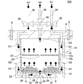
- FIG. 3 is a schematic cross-sectional view for explaining a gas flow of a carrier gas, an evaporated evaporation material, and a mixed gas in the evaporation material container shown in FIG. 2. It is sectional drawing which shows the other example of the container for evaporation materials typically. It is sectional drawing which shows typically the other example of the container for evaporation materials. It is a top view which shows typically the shelf member shown in FIG.
- Solid-state vaporization supply system of metal halogen compound for thin film formation is a solid vaporization supply system 500 as shown in FIG.
- the solid vaporization supply system of the metal halide compound for forming a thin film of the present embodiment may be simply referred to as “solid vaporization supply system”.
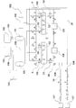
- FIG. 1 is a block diagram showing the configuration of an embodiment of a solid-state vaporization and supply system for a metal halide compound for forming a thin film of the present invention.
- a solid vaporization supply system 500 of the present embodiment includes an evaporation source container 100 for storing and evaporating a thin film forming metal halogen compound as an evaporation source, and an evaporation source container 100. And a connected buffer tank 101.
- reference numeral 102 indicates a raw material supply source 102 for supplying the metal halide compound A for forming a thin film to the evaporation raw material container 100.
- the metal halide compound A for forming a thin film may be supplied to the evaporation source container 100 in any of a liquid phase, a solid phase and a gas phase.
- Reference numeral 103 indicates a semiconductor processing facility 103, in which film formation by chemical vapor deposition (CVD) method, metalorganic chemical vapor deposition (MOCVD) method, atomic layer deposition (ALD) method is performed.
- the semiconductor processing equipment 103 is equipment (for example, a reaction chamber of a CVD apparatus) in which a substrate to be coated is arranged, and a desired thin film is formed on the substrate arranged in the semiconductor processing equipment 103.
- Reference numeral 104 indicates the heat exchanger 104.
- Reference numeral 105 indicates a temperature controller.
- Reference numeral 106 denotes a supply control unit 106 that controls the supply amount of the mixed gas G3 supplied from the buffer tank 101.
- Examples of the constituent elements of the supply control means 106 include a control valve, a flow meter, and a pressure gauge.
- Reference numeral 107 indicates a carrier gas supply means 107.
- Examples of the carrier gas G1 include hydrogen, helium, nitrogen, oxygen, argon, carbon monoxide, carbon dioxide, and the like.
- the carrier gas supply means 107 depicted on the upper side of the paper supplies nitrogen as the carrier gas G1
- the carrier gas supply means 107 depicted on the lower side of the paper supplies argon as the carrier gas G1.
- the semiconductor processing equipment 103 is a processing equipment used in the solid vaporization supply system 500, and is not a component of the solid vaporization supply system 500 of the present embodiment.
- the raw material supply source 102, the heat exchanger 104, the temperature controller 105, the supply control means 106, and the carrier gas supply means 107 are constituent elements that are appropriately and incidentally added to the solid vaporization supply system 500 of the present embodiment. is there.
- the respective constituent elements that exchange various gases are connected to each other via a gas pipe 34.
- the mixed gas G3 of the thin film forming metal halogen compound G2 evaporated in the evaporation source container 100 and the carrier gas G1 introduced into the evaporation source container 100 is supplied to the buffer tank 101. And a desired amount of the mixed gas G3 is supplied from the buffer tank 101 to the semiconductor processing facility 103. Therefore, according to the solid vaporization supply system 500 of the present embodiment, it is possible to realize the supply of the mixed gas G3 at a high flow rate.
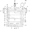
- the evaporation raw material container 100 includes a container body 2, a lid body 4, a fastening member 6, and a joint member 8.
- FIG. 2 is a cross-sectional view schematically showing an evaporation raw material container used in one embodiment of the solid-state vaporization and supply system for a metal halide compound for forming a thin film of the present invention.
- FIG. 3 is a schematic diagram for explaining the gas flows of the carrier gas G1, the evaporated evaporation material (that is, the evaporated metal halide compound G2 for forming a thin film), and the mixed gas G3 in the evaporation material container shown in FIG. FIG.
- the container body 2 has a container wall 12, and is a substantial body part of the evaporation raw material container 100.
- the lid 4 is configured to be attachable to and detachable from the container body 2, and has a carrier gas inlet 16 for introducing the carrier gas G1 into the container body 2 and a mixed gas G3 of the evaporated thin film forming metal halogen compound G2 and the carrier gas G1. It has a mixed gas lead-out port 18 for leading the gas to the outside.
- the fastening member 6 is for fixing the container body 2 and the lid body 4.
- the fastening member 6 is a bolt inserted into a bolt insertion hole provided in the vessel body 2 and the lid body 4. Examples include a member and a nut member screwed and fastened to the bolt member.
- the joint member 8 connects the carrier gas inlet 16 and the mixed gas outlet 18 of the lid 4 to the valve 30, the pressure gauge 32, the flow meter (not shown), and other gas pipes. It is a thing.
- the container wall 12 of the container body 2 has a double wall structure 14 constituted by an inner wall member 12a and an outer wall member 12b. Then, the carrier gas G1 introduced from the carrier gas introduction port 16 is introduced into the container body 2 via the space between the inner wall member 12a and the outer wall member 12b of the double wall structure 14. With this configuration, when the container body 2 is heated from the outside, the carrier gas G1 introduced into the container body 2 can be simultaneously heated. Therefore, the heated carrier gas G1 can be brought into contact with the thin film-forming metal halogen compound S filled in the container body 2, and the thin film-forming metal halogen compound S is stably vaporized at a high flow rate. Can be made.
- the inside of the container body 2 can be heated via the inner wall member 12a of the container wall 12.
- the metal halide compound for forming a thin film filled in the container body 2 is indicated by a symbol S, and in FIG. 1, the metal halide compound for forming a thin film supplied from the raw material supply source 102 is shown. , Symbol A.
- the container wall 12 of the container body 2 is made of copper having a purity of 99 to 99.9999%, aluminum having a purity of 99 to 99.9999%, or titanium having a purity of 99 to 99.9999%.
- the container body 2, the lid 4, the fastening member 6, and the joint member 8 are each provided with a fluororesin coating 10.
- the surface of each of the container body 2, the lid 4, the fastening member 6, and the joint member 8 may be electrolytically polished. Further, the fluororesin coating 10 may be further applied to each surface subjected to electrolytic polishing. Therefore, the evaporation raw material container 100 has excellent corrosion resistance.
- the evaporation raw material container 100 includes the fluororesin coating 10 and/or the container body 2, the lid body 4, the fastening member 6, and the joint member 8, and particularly at the portions that do not substantially come into contact with the thin film forming metal halogen compound S. Or, since it is subjected to electrolytic polishing, it has extremely excellent corrosion resistance. Therefore, according to the solid vaporization supply system 500 (see FIG. 1) using the evaporation raw material container 100 configured as described above, particle contamination can be effectively reduced.
- the container wall 12 of the container body 2 is made of copper having a purity of 99 to 99.9999%, aluminum having a purity of 99 to 99.9999%, or titanium having a purity of 99 to 99.9999%, The thermal conductivity is excellent, and the inside of the container wall 12 can be heated well.
- the carrier gas G1 comes into contact with the outer wall of the container wall 12 so that the carrier gas G1 introduced into the container body 2 can be satisfactorily heated, The vaporization of the metal halide compound S for forming a thin film can be further promoted.
- the preheated carrier gas G1 into the evaporation source container 100, it is possible to effectively heat the inside of the container body 2 via the inner wall member 12a of the container wall 12.
- the term "purity” means the proportion (weight ratio) of the main components in the sample determined by quantitative analysis. If the purity of copper, aluminum or titanium forming the container wall 12 is less than 99%, it is not preferable in that the thermal conductivity of the container wall 12 is lowered. Further, if the purity of copper, aluminum or titanium constituting the container wall 12 exceeds 99.9999%, it is not preferable in that the strength of the container wall 12 is reduced.
- container wall 12 is a concept that includes not only the side wall but also the bottom wall. That is, when the evaporation raw material is put into the evaporation raw material container 100, it is preferable that the wall portion in contact with the evaporation raw material is the container wall.
- the carrier gas G1 is introduced into the container body 2 through the space between the inner wall member 12a and the outer wall member 12b at the bottom surface of the inner wall member 12a that constitutes the container wall 12.
- the container has an inlet 20.
- Reference numeral 30 in FIGS. 2 and 3 indicates a valve 30 for opening and closing the flow path of the evaporation raw material container 100.
- the carrier gas G1 can be introduced into the evaporation source container 100 (inside the container body 2) or the mixed gas G3 with the carrier gas G1 can be led out of the container body 2.
- the evaporation raw material container 100 can include two or more open/close valves.
- reference numeral 32 in FIG. 2 indicates a pressure gauge
- reference numeral 34 in FIG. 3 indicates a gas pipe.
- the material forming the fluororesin coating 10 is not particularly limited and may be any coatable fluororesin.
- a resin in which at least a part of hydrogen is replaced by fluorine can be used.
- examples thereof include polytetrafluoroethylene (trade name “Teflon” (registered trademark)) and the like. With such a material, it is possible to more favorably prevent impurities from mixing in the evaporation raw material.
- the thickness of the fluororesin coating 10 is not particularly limited, but for example, preferably 150 to 500 ⁇ m, more preferably 200 to 400 ⁇ m, and particularly preferably 250 to 350 ⁇ m. The thickness of about 300 ⁇ m is most preferable. If the thickness of the fluororesin coating 10 is less than the above lower limit value, sufficient corrosion resistance may not be obtained. If it exceeds the above upper limit, the layer may become too thick.
- the fluororesin coating 10 can be formed, for example, by vapor deposition, but the vapor deposition method can employ a conventionally known method and is not particularly limited.
- Fluorine resin coating 10 is preferably applied to all of the inner and outer surfaces of the container body 2, the inner and outer surfaces of the lid 4, the surface of the fastening member 6, and the surface of the joint member 8. That is, it is considered that the fluororesin coating 10 does not normally contact not only the surface (inner surface) contacting the carrier gas G1, the evaporated metal halide compound G2 for forming a thin film and the mixed gas G3, but also the above-mentioned gases. It is preferable that it is applied to the entire area including the surface (outer surface) of each member.
- the electrolytic polishing performed on the container body 2 or the like is preferably, for example, a polishing treatment performed under the following condition (i).
- a polishing treatment performed under the following condition (i).
- polishing conditions are a pressure of 20 to 60 kPa, a rotation speed of 350 rpm or less, and inorganic particles having an abrasive grain size of 0.020 to 0.10 ⁇ m are used as the abrasive grains.
- the current density is preferably 15 to 20 mA/cm 2 .
- the pH of the electrolytic solution is preferably 11 to 11.5.
- the rotation number of the polishing condition may be 50 to 350 rpm.
- Inorganic particles are used as the abrasive particles, and the inorganic particles are not particularly limited, but examples thereof include colloidal silica (Colloidal SiO 2 ).
- electrolytic polishing Whether or not electrolytic polishing has been performed can be confirmed, for example, by observing the surface with a microscope using both an electron microscope and an atomic force microscope (AFM).
- AFM atomic force microscope
- a method of inspecting the surface state by secondary electron mass spectrometry can be mentioned.
- the evaporation raw material container 100 has a container body 2, a lid body 4, a fastening member 6, and a joint member 8 each provided with a fluororesin coating 10 and/or electrolytic polishing. And may be chemically polished. Even with this structure, excellent corrosion resistance can be imparted. Further, when the fluororesin coating 10 is further applied after chemical polishing, the adhesion of the fluororesin coating 10 is further improved as in the case of performing electrolytic polishing. For example, contamination of moisture, oxygen, etc. at the interface with the fluororesin coating 10 is reduced, and the adhesion of the fluororesin coating 10 can be improved.
- Materials for the lid 4 and the fastening member 6 are not particularly limited, and examples thereof include aluminum, copper, titanium, nickel alloy, aluminum alloy, super stainless steel, and stainless steel.
- nickel alloys include, for example, Hastelloy, Inconel, and the like, and “Hastelloy” and “Inconel” are alloys containing Ni and Mo.
- Aluminum, copper, and titanium preferably have a purity of 99% or more, more preferably 99 to 99.9999%.
- the composition of “Hastelloy” can be appropriately determined, but specifically, Ni is 40 to 60 mass% and Mo is 30 to 50 mass %.
- Ni is 20 to 50 mass% and Mo is 70 to 50 mass %.
- Super stainless steel means Ni 17.00 to 19.50 mass%, Cr 19.00 to 21.00 mass%, Mo 5.50 to 6.50 mass%, and N 0.16 to 0 mass%. .24% by mass, Cu 0.50 to 1.00% by mass, further, C is 0.020% by mass or less, Si is 0.80% by mass or less, Mn is 1.00% by mass or less, and P is 0. A stainless steel having 0.030% by mass or less and S of 0.015% by mass or less and having further improved corrosion resistance.
- the container main body 2 further has one or more members having a maximum length in one direction of 1 to 30 mm and made of aluminum or copper. Good.
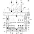
- the evaporation raw material container 200 shown in FIG. 4 further includes one or more spherical members 26 made of aluminum and having a diameter of 2 to 30 mm.
- the member (for example, the spherical member 26 in FIG. 4) included in the container body 2 is preferably a spherical member, an oblong member, a leaf-like member, a spiral member, or any other irregular member. In the case of a leaf-shaped member, its width is preferably about 1 to 2 cm.
- the length in the longitudinal direction is preferably about 1.5 to 3 cm. Also in the case of other irregularly shaped members, the length in the longitudinal direction is preferably about 1.5 to 3 cm.
- a member is made of aluminum, copper, or titanium, and may be made of the same material as the container wall 12, for example.
- the container wall 12 is made of copper having a purity of 99 to 99.9999%
- the spherical member 26 is preferably made of copper.
- FIG. 4 is a cross-sectional view schematically showing another example of the evaporation raw material container. 4, constituent elements similar to those of the evaporation raw material container 100 shown in FIGS. 2 and 3 are denoted by the same reference numerals, and description thereof may be omitted.
- the spherical member 26 made of aluminum as shown in FIG. 4 in the container body 2 for example, there is an advantage that the heat conduction of the compound in the container body 2 can be increased.
- the number of members such as the spherical member 26 shown in FIG. 4 arranged in the container body 2 is not particularly limited, but is preferably 10 to 20 for example.
- the evaporation raw material container 100 shown in FIGS. 2 and 3 may further include at least one plate-shaped shelf member 22 suspended in the container body 2.
- the metal halide compound S for forming a thin film may be arranged on such a shelf member 22.
- One or more through holes 24 are formed in the shelf member 22, and the gas flow of the carrier gas G1, the evaporated thin film-forming metal halide compound G2, and the mixed gas G3 in the container body 2 by the through holes 24. Is done.
- the shelf member 22 may be made of, for example, a porous body. Further, in the shelf member 22 formed of a porous body, one or more through holes 24 as shown in FIGS. 2 and 3 may not be formed. Gas flow of the carrier gas G1, the evaporated thin film forming metal halide compound G2, and the mixed gas G3 is performed in the container body 2 by the porous body forming the shelf member 22. Further, in the shelf member 22 formed of a porous body, the shelf member 22 itself has a function of a filter, and the particles generated in the container body 2 can be collected and removed by the shelf member 22. Further, as the porous body forming the shelf member 22, for example, ceramic can be cited.
- FIG. 5 is a cross-sectional view schematically showing still another example of the evaporation raw material container. 5, the same components as those of the evaporation source container 100 shown in FIGS. 2 and 3 are designated by the same reference numerals, and the description thereof may be omitted.
- the arrangement of the plurality of through holes 24 formed in the shelf member 22 is not particularly limited.
- the through holes 24 are evenly formed on the surface of the shelf member 22. Good.
- a plurality of through holes are sequentially formed so as to circulate around the shelf member, and the loci of the plurality of through holes are spiral. May be arranged so as to draw.
- FIG. 6 is a top view schematically showing the shelf member shown in FIG.
- the metal halide compound S for forming a thin film as an evaporation raw material filled in the evaporation raw material container 100 as shown in FIGS. 2 and 3 is preferably a compound represented by the following general formula (2).
- MXn (However, in the general formula (2), M is Al, Hf, Zr, Ta, W, Ga, La, Ce, Pr, Nd, Sm, Eu, Gd, Tb, Dy, Er, Tm, Yb and (Any element of Co is shown, X is a halogen element, and n is the number of X.)
- the halogen element of X is chlorine (Cl), aluminum chloride (AlCl 3 ), hafnium chloride (HfCl 4 ), zirconium chloride (ZrCl 4 ), chloride Tantalum (TaCl 5 ), tungsten pentachloride (WCl 5 ), tungsten hexachloride (WCl 6 ), gallium chloride (GaCl 3 ), lanthanum chloride (LaCl 3 ), cerium chloride (CeCl 3 ), praseodymium chloride (PrCl 3 ), Neodymium chloride (NdCl 3 ), samarium chloride (SmCl 3 ), europium chloride (EuCl 3 ), gadolinium chloride (GdCl 3 ), terbium chloride (TbCl 3 ), dysprosium chloride (DyCl 3 ), erbium chloride (Er
- the evaporation raw material container 100 can satisfactorily store even an evaporation raw material having a strong corrosive property such as the compound represented by the general formula (2), and the ratio of impurities present in the evaporation raw material is very high. Get smaller.
- the evaporation raw material container 100 is a container capable of contacting with a heating medium or a cooling medium that can be heated or cooled from the outside and holding the compound in the container in either a gas state or a solid state.
- the buffer tank 101 used in the solid vaporization supply system 500 shown in FIG. 1 is preferably made of a material having good thermal conductivity, for example. Further, as the buffer tank 101, for example, one in which SUS316 is electrolytically polished and 4N or 5N high-purity Al is bonded to the inner surface thereof can be mentioned. Further, the buffer tank 101 may be made of high-purity 4N or 5N Al and constitutes the main body of the buffer tank 101. For example, the buffer tank 101 is preferably made of a material having a thickness capable of withstanding a pressure of 49 N or more. As a method of using the buffer tank 101, for example, a mixed gas having a pressure of the carrier gas can be stored and used.
- a method of reducing pressure/flow rate fluctuations while generating a mixed gas in an evaporation raw material container can be used, or as another method, for example, a buffer tank 101 can be used. It is also possible to prepare two and use them by switching (that is, use a mixed gas like a cylinder). For example, the method of preparing and using two buffer tanks 101 is more preferable in that the supply pressure of the mixed gas can be kept constant while changing the flow rate of the mixed gas.
- the internal capacity of the buffer tank 101 is not particularly limited, but it is preferably, for example, 10 to 100 times the internal capacity of the container body of the evaporation raw material container. With such a configuration, the mixed gas stored in the buffer tank 101 can be stably supplied.
- the valve 30 disposed in a part of the gas flow path connecting the evaporation raw material container 100 and the buffer tank 101 has a CV value (water replacement) of 0.2 or more. It is preferred that In particular, this valve is more preferably a vacuum valve represented by a bellows valve. By providing such a valve, the mixed gas can be supplied more effectively. If the CV value (water replacement) is less than 0.2, the flow of a large flow rate of the mixed gas may be hindered, and the mixed gas may stay in the valve.
- the valve When the mixed gas stays in the valve, the heat of vaporization causes a temperature decrease, and the evaporation raw material (metal halide compound for thin film formation) is fixed in the valve and the valve may be closed.
- the CV value of the valve is preferably 0.2 or more, more preferably 0.6 or more, and particularly preferably 1.0 or more.
- the upper limit value of the CV value is not particularly limited, but may be 3.0 or 2.5, for example.
- Examples of the CV value valve as described above include a diaphragm, a ball valve, and a bellows valve. It is preferable that these valves do not depend on the valve function, body material, seat material, or temperature.
- the CV value of the valve is the value of water replacement measured by fully opening the valve and allowing water to flow.
- the flow rate of the fluid (water) flowing through the bubble is measured on the inflow side and the outflow side of the valve.
- a flow meter is used to measure the flow rate Q of the fluid flowing through the valve.
- pressure gauges are arranged in front of and behind the valve, and the pressure loss ⁇ P of the fluid passing through the valve is measured.
- the flow rate Q of the fluid and the pressure loss ⁇ P when passing through the valve will be measured according to the actual usage conditions.
- the measurement is performed so that the value is close to the actual usage condition.
- the flow rate Q of water can be determined from the specific gravity of the mixed gas and the specific gravity of water.
- the specific gravity of water is 1, the specific gravity of each evaporation material (for example, 1.40 to 1.68) and the flow rate of carrier gas is set to 500 cc/min, the flow rate Q of water is 300 cc/min. It becomes a degree.
- the CV value shall be measured under the condition of 15°C.
- the evaporation raw material container 100 configured as described above can extremely effectively reduce particle contamination in the solid vaporization supply system 500 shown in FIG. Therefore, the solid vaporization supply system 500 of the present embodiment can be effectively used for film formation by chemical vapor deposition (CVD) method, metalorganic chemical vapor deposition (MOCVD) method, atomic layer deposition (ALD) method.
- the atomic layer deposition (ALD) method is a method capable of forming a film thinner than the film formed by the chemical vapor deposition (CVD) method, and forms a very thin film of about several nm.
- the accuracy of the film is easily affected by the impurities contained in the evaporation raw material. Therefore, by using the solid vaporization supply system 500 of the present embodiment, the amount of particles (impurities) contained in the evaporation raw material can be made extremely small.
- the evaporation raw material container for the solid vaporization supply system can be manufactured, for example, as follows. First, the outer wall member of the container wall forming the container body is made of stainless steel or the like by a conventionally known method. Then, the inner wall member of the container wall constituting the container body is made of copper having a purity of 99 to 99.9999%, aluminum having a purity of 99 to 99.9999%, or titanium having a purity of 99 to 99.9999%. Then, the inner wall member is arranged inside the outer wall member to manufacture the container body. In addition, a lid body that is detachably attached to the container body is manufactured.
- a bolt insertion hole for arranging a fastening member is formed in the container body and the lid, and a bolt member and a nut member as a fastening member suitable for the bolt insertion hole are prepared. Further, various joint members to be arranged at the carrier gas inlet and the mixed gas outlet of the lid are prepared. In this way, each untreated member for forming the evaporation material container is obtained (preparing step).
- each member prepared is polished as necessary (polishing process). Specifically, the inner surface of each member is subjected to a polishing treatment to obtain each polished member. In the polishing treatment, it is preferable to perform electrolytic polishing treatment under the above-mentioned condition (i).
- the fluororesin coating can be formed by vapor deposition.
- the fluororesin coating when the electrolytic polishing treatment under the above-mentioned condition (i) is performed, the fluororesin coating may not be applied.
- each member is assembled to make a container for evaporation raw material (assembly process).
- the evaporation raw material container for the solid vaporization supply system can be manufactured.
- a SUS tank is manufactured.
- an instrument made of SUS that can measure the pressure above and below is attached, and a pressure valve provided with an H-type purge gas line is connected to the film forming chamber side.
- a three-way valve is attached to the supply line on the cylinder side of the SUS tank.
- the supply gas is sent to a tank made of SUS at a pressure equal to or higher than the saturated vapor pressure, and the temperature on the supply side of the buffer tank by the external heating method is 200° C. to 250° C.
- the inside of the buffer tank is preferably subjected to an inner surface treatment with a material containing aluminum and/or Hastelloy after the inner surface is electrolytically polished.
- Such inner surface treatment can be performed by joining or welding.
- the solid vaporization supply system of the present invention can be manufactured by connecting the produced evaporation material container and the buffer tank with a gas pipe. It should be noted that it is preferable to appropriately install instruments such as an on-off valve, a control valve, a flow meter, and a pressure gauge in the gas pipe connecting the evaporation raw material container and the buffer tank.
- a vacuum valve having a CV value (water substitution) of 0.2 or more can be preferably used as a valve arranged in a part of a gas flow path connecting the evaporation raw material container and the buffer tank.
- the carrier gas inlet 16 (see FIG. 2) of the evaporation source container 100 is connected to the carrier gas supply means 107.
- the mutual connection is performed by the gas pipe 34, and it is preferable to appropriately provide an instrument such as an on-off valve, a control valve, a flow meter, and a pressure gauge.
- the mixed gas outlet 18 (see FIG. 2) of the evaporation raw material container 100 is connected to the buffer tank 101.
- the evaporation raw material container 100 is connected to a raw material supply source 102 for supplying the thin film forming metal halogen compound A to the evaporation raw material container 100.
- These connections can also be made by the gas pipe 34.
- the supply control means 106 for controlling the supply amount and the like of the mixed gas G3 supplied to the buffer tank 101 is connected, and the semiconductor processing equipment 103 is connected via this supply control means 106.
- the metal halide compound A for forming a thin film as an evaporation material is charged from the material supply source 102 into the evaporation material container 100. Then, the evaporation raw material container 100 is closed.
- the carrier gas G1 is introduced into the evaporation material container 100 from the carrier gas supply means 107. Then, the evaporation raw material (the evaporated metal halogen compound G2 for forming a thin film) and the carrier gas G1 mixed in the evaporation raw material container 100 are mixed, and the mixed gas G3 is derived from the mixed gas outlet 18 (see FIG. 2). To be done.
- the evaporated raw material is evaporated (vaporized) by heating or the like to become a raw material gas.
- the carrier gas G1 is introduced, as shown in FIGS. 2 and 3, the container wall 12 of the container body 2 is heated to heat the thin film forming metal halide compound S in the container body 2.
- the carrier gas G1 is introduced from the carrier gas introduction port 16 of the lid body 4, and is passed through between the inner wall member 12a and the outer wall member 12b of the double wall structure 14 of the heated container wall 12, and the heated carrier gas G1 is introduced into the container body 2. Then, the evaporated metal halide compound G2 for forming a thin film and the carrier gas G1 are mixed to prepare a mixed gas G3. With this structure, the heated carrier gas G1 can be brought into contact with the thin film-forming metal halogen compound S, and the thin film-forming metal halogen compound S can be vaporized stably and at a high flow rate. it can.
- the mixed gas G3 derived from the evaporation raw material container 100 is stored in the buffer tank 101 via the gas pipe 34.
- the buffer tank 101 For example, two or more buffer tanks 101 are provided, and a predetermined amount of mixed gas G3 is stored in the first buffer tank 101, and then the mixed gas G3 is sequentially stored in the second and subsequent buffer tanks 101. Is preferred.
- the mixed gas G3 as a film forming gas is supplied from the buffer tank 101 to the semiconductor processing equipment 103, and in the semiconductor processing equipment 103, a chemical vapor deposition (CVD) method, a metal organic chemical vapor deposition (MOCVD) method, Film formation by an atomic layer deposition (ALD) method or the like is started.
- the supply of the mixed gas G3 to the semiconductor processing equipment 103 is adjusted by the supply control means 106 to a predetermined pressure and flow rate.
- the evaporation material container 100 has excellent corrosion resistance, and the ratio of impurities derived from the container in the evaporation material is extremely small. Therefore, the high-purity mixed gas G3 can be supplied to the semiconductor processing facility 103.
- the container wall of the container body of the evaporation source container was made of the materials shown in "Material” and “Purity (%)" of "Container Wall” in Tables 1 and 2. Further, the surfaces of the container body, the lid, the fastening member, and the joint member were polished under the following polishing conditions (i). Then, a fluororesin coating was applied on the surface of each member that had been subjected to the polishing treatment.
- the fluororesin coating was performed by depositing polytetrafluoroethylene (Teflon) using an apparatus that performs vapor deposition by electron irradiation vacuum vapor deposition.
- the pressure was 31.35 kPa
- the rotation speed was 300 rpm
- colloidal silica having an abrasive grain size of 0.07 ⁇ m was used as the abrasive grains.
- a buffer tank by the following method.
- a tank made of SUS was manufactured.
- the prepared SUS tank was equipped with instruments made of SUS capable of measuring pressure above and below, and a pressure valve provided with an H-type purge gas line was connected to the film forming chamber side.
- a three-way valve was attached to the supply line on the cylinder side of the SUS tank.
- the supply gas was sent to the SUS tank at a pressure equal to or higher than the saturated vapor pressure, and the temperature of the supply side of the buffer tank was 200°C to 250°C and the temperature of the film forming chamber was 300°C by the external heating method.
- the pressure gauge near the film forming chamber was designed to maintain a constant supply pressure while maintaining a temperature of up to 400°C.
- the capacities of the buffer tanks manufactured in each of the examples and comparative examples are shown in the "buffer tank capacity (L)" column of Tables 1 to 6.
- a solid vaporization supply system was created by connecting the evaporation raw material container and the buffer tank with gas piping.
- the gas pipe serves as a gas flow path through which the mixed gas generated by the evaporation raw material container passes.
- a valve having a CV value (water substitution) of 1.5 was arranged in a part of the gas pipe connecting the evaporation raw material container and the buffer tank, and the mixed gas was supplied through such a valve. ..
- Example 16 to 30 containers for evaporating raw materials were produced in the same manner as in Examples 1 to 15 except that the fluororesin coating was not applied. That is, in the evaporation raw material containers of Examples 16 to 30, the surfaces of the container body, the lid, the fastening member, and the joint member were only subjected to the polishing treatment under the above polishing conditions (i). In each of Examples 16 to 30, the container wall of the container body of the evaporation raw material container was made of the materials shown in "Material” and “Purity (%)" of "Container wall” in Table 3.
- a buffer tank was manufactured by the method described above, and the evaporation raw material container and the buffer tank were connected by a gas pipe to manufacture a solid vaporization supply system.
- a valve having a CV value (water substitution) of 1.5 was arranged in a part of the gas pipe connecting the evaporation raw material container and the buffer tank, and the mixed gas was supplied through such a valve. ..
- the metal halogen compound for thin film formation shown in the column of “raw material (metal halogen compound)” in Tables 1 to 3 is stored, and a carrier gas is supplied into the container body to form an evaporated thin film.
- a mixed gas was produced by mixing the metal halogen compound for use with a carrier gas.
- the generated mixed gas was once stored in a buffer tank, and the mixed gas stored in this buffer tank was used to perform film formation by an atomic layer deposition (ALD) method.
- Tables 4 to 6 show the compositions of ALD films formed by the atomic layer deposition (ALD) method.
- the amounts of impurities (12 elemental elements shown in Tables 4 to 6) in the evaporated raw material after film formation were measured by ICPMS (inductively coupled plasma mass spectrometry).
- ICPMS inductively coupled plasma mass spectrometry
- Tables 4 to 6 show the flow rates of the reaction gas used for forming the ALD film in each of the examples and comparative examples.
- the flow rates of the reaction gases in Tables 1 to 3 indicate the flow rates of the reaction gas generated by the evaporation raw material container.
- the amount of impurities was measured by the following method. First, after the film formation, the residue of the evaporation raw material remaining in the container body of the evaporation raw material container was recovered. Next, the recovered material was dissolved in a predetermined amount using aqua regia in an ICPMS (inductively coupled high frequency plasma mass spectrometry) apparatus. Then, this was heated to 120° C. on a hot plate to evaporate to dryness. Then, the evaporated sample was diluted to obtain a measurement sample. After that, metal impurities in the measurement sample were measured by the above analyzer.
- ICPMS inductively coupled high frequency plasma mass spectrometry
- the surface roughness of the inner surface of the container body 2 was measured before and after the film formation by an AFM (atomic force microscope) analyzer (manufactured by HORIBA). This surface roughness was measured several times and the average value was calculated. A value was calculated by dividing A by B, where A is the surface roughness before film formation and B is the surface roughness before film formation. The calculated "A/B" values are shown in the "Internal surface roughness" column of Tables 4 to 6.
- the growth rate (GPC; Growth Per Cycle) was measured. Specifically, during the above-described film formation, the valve is opened/closed once every 0.2 seconds to introduce the mixed gas containing the evaporation material into the film formation chamber. One cycle of valve opening and closing is 0.2 seconds, and the film thickness formed on an 8-inch silicon wafer is measured to calculate the film growth rate per unit time (1 cycle).
- Example 31 to 45 evaporation raw material containers were manufactured by the same method as in Examples 1 to 15.
- Example 31 the same evaporation source container as in Example 1 was produced, and thereafter, in Example 32 and subsequent examples, the evaporation source containers corresponding to Example 2 and subsequent examples were also produced.
- a buffer tank was manufactured by the method described above, and the evaporation raw material container and the buffer tank were connected by a gas pipe to manufacture a solid vaporization supply system.
- a valve having a CV value (water substitution) of 1.5 was arranged in a part of the gas pipe connecting the evaporation raw material container and the buffer tank, and the mixed gas was supplied through such a valve. ..
- the capacity of the buffer tank is as shown in Table 7. Then, a film was formed by an atomic layer deposition (ALD) method in the same manner as in Examples 1 to 15. In Examples 31 to 45, a mixed gas was generated without filling a filling material such as a spherical member in the evaporation raw material container.
- ALD atomic layer deposition
- Comparative Examples 17 to 32 evaporation material containers were produced by the same method as in Comparative Examples 1 to 16.
- Comparative Example 17 an evaporation source container similar to that of Comparative Example 1 was produced, and hereinafter, also in Comparative Example 18 and later, the evaporation source containers corresponding to Comparative Example 2 and later were produced.
- Comparative Examples 17 to 32 atomic layer deposition was performed by using a vaporization raw material container and a gas pipe connected to the solid vaporization supply system without using a buffer tank and directly supplying a mixed gas from the vaporization raw material container.
- a film was formed by the (ALD) method.
- Tables 7 and 8 show the compositions of ALD films formed by the atomic layer deposition (ALD) method in Examples 31 to 45 and Comparative Examples 17 to 32. Further, the amounts of impurities (12 elemental elements shown in Tables 7 and 8) in the evaporated raw material after film formation were measured by ICPMS (inductively coupled plasma mass spectrometry). In the column of "Before film formation” in Table 7, the amount of impurities (12 kinds of elements shown in Tables 7 and 8) in the evaporation raw material before film formation is described. Tables 7 and 8 show the flow rates of the reaction gas in each Example and Comparative Example. In addition, the “internal surface roughness” and the “growth rate” were measured by the same method as described above. The results are shown in Tables 7 and 8.
- the solid vaporization supply systems of Examples 1 to 45 have smaller amounts of impurities than the solid vaporization supply systems of Comparative Examples 1 to 32. Further, in the evaporation raw material containers of the solid vaporization supply systems of Examples 1 to 45, the value of “A/B” of “internal surface roughness” was close to 1, and the difference in surface roughness before and after film formation was small. It turns out to be small. Here, the fact that the difference in the surface roughness is small means that the degree of corrosion by the evaporating raw material was small, and it can be seen that the corrosion resistance is high.
- the solid vaporization supply systems of Examples 1 to 45 (especially, the evaporation raw material container) have excellent corrosion resistance. Further, since the solid vaporization supply systems of Examples 1 to 45 are provided with the buffer tanks on the downstream side of the evaporation raw material container, the mixed gas containing the evaporation raw materials can be stably supplied at a high flow rate, It was possible to realize an excellent growth rate in the growth of the ALD film.
- the solid vaporization supply system of a metal halide compound for forming a thin film of the present invention is used for film formation by a chemical vapor deposition (CVD) method, a metal organic chemical vapor deposition (MOCVD) method, an atomic layer deposition (ALD) method.
- CVD chemical vapor deposition
- MOCVD metal organic chemical vapor deposition
- ALD atomic layer deposition
Landscapes
- Chemical & Material Sciences (AREA)
- Chemical Kinetics & Catalysis (AREA)
- Engineering & Computer Science (AREA)
- Materials Engineering (AREA)
- Metallurgy (AREA)
- Organic Chemistry (AREA)
- General Chemical & Material Sciences (AREA)
- Mechanical Engineering (AREA)
- Inorganic Chemistry (AREA)
- Electrochemistry (AREA)
- Chemical Vapour Deposition (AREA)
Abstract
L'invention concerne un système d'alimentation par vaporisation solide d'un composé halogène métallique pour former un film mince, lequel permet de réduire la contamination particulaire. Ce système comporte: un contenant (100) pour matière première de vaporisation, destiné à recueillir et à vaporiser un composé halogène métallique pour former un film mince; et un réservoir (101) pour solution tampon, lequel est relié au contenant (100) pour matière première de vaporisation. Le contenant (100) pour matière première de vaporisation comporte: un corps principal de contenant possédant une paroi de contenant; un couvercle; un élément de fixation; et un élément de liaison. La paroi de contenant: possède une structure à double paroi constituée d'un élément de paroi interne et d'un élément de paroi externe; et est conçue de façon qu'un gaz vecteur soit introduit à l'intérieur du corps principal de contenant par l'intermédiaire de la structure à double paroi. La paroi de contenant est constituée de cuivre à un degré de pureté de 99 à 99,9999%, d'aluminium à un degré de pureté de 99 à 99, 9996% ou de titane à un degré de pureté de 99 à 99,9999%. Un revêtement de résine fluorée et/ou un polissage électrolytique sont appliqués au corps principal de contenant, au couvercle, à l'élément de fixation et à l'élément de liaison.
Priority Applications (3)
| Application Number | Priority Date | Filing Date | Title |
|---|---|---|---|
| US17/424,968 US11613809B2 (en) | 2019-02-07 | 2020-02-05 | Solid vaporization/supply system of metal halide for thin film deposition |
| KR1020217028595A KR102475511B1 (ko) | 2019-02-07 | 2020-02-05 | 박막 형성용 금속 할로겐 화합물의 고체 기화 공급 시스템 |
| CN202080013066.8A CN113366142A (zh) | 2019-02-07 | 2020-02-05 | 薄膜形成用金属卤化物的固体气化供给系统 |
Applications Claiming Priority (2)
| Application Number | Priority Date | Filing Date | Title |
|---|---|---|---|
| JP2019-020584 | 2019-02-07 | ||
| JP2019020584A JP6901153B2 (ja) | 2019-02-07 | 2019-02-07 | 薄膜形成用金属ハロゲン化合物の固体気化供給システム。 |
Publications (1)
| Publication Number | Publication Date |
|---|---|
| WO2020162500A1 true WO2020162500A1 (fr) | 2020-08-13 |
Family
ID=71948041
Family Applications (1)
| Application Number | Title | Priority Date | Filing Date |
|---|---|---|---|
| PCT/JP2020/004368 Ceased WO2020162500A1 (fr) | 2019-02-07 | 2020-02-05 | Systeme d'alimentation par vaporisation solide d'un compose halogene metallique pour former un film mince |
Country Status (6)
| Country | Link |
|---|---|
| US (1) | US11613809B2 (fr) |
| JP (1) | JP6901153B2 (fr) |
| KR (1) | KR102475511B1 (fr) |
| CN (1) | CN113366142A (fr) |
| TW (1) | TWI741495B (fr) |
| WO (1) | WO2020162500A1 (fr) |
Cited By (3)
| Publication number | Priority date | Publication date | Assignee | Title |
|---|---|---|---|---|
| CN114277357A (zh) * | 2020-09-28 | 2022-04-05 | 株式会社国际电气 | 气化系统、基板处理装置以及半导体装置的制造方法 |
| US11566326B2 (en) * | 2019-02-07 | 2023-01-31 | Kojundo Chemical Laboratory Co., Ltd. | Vaporizable source material container and solid vaporization/supply system using the same |
| US11613809B2 (en) | 2019-02-07 | 2023-03-28 | Kojundo Chemical Laboratory Co., Ltd. | Solid vaporization/supply system of metal halide for thin film deposition |
Families Citing this family (9)
| Publication number | Priority date | Publication date | Assignee | Title |
|---|---|---|---|---|
| WO2021054216A1 (fr) * | 2019-09-18 | 2021-03-25 | 東京エレクトロン株式会社 | Système d'alimentation en gaz d'alimentation et procédé d'alimentation en gaz d'alimentation |
| CN115244215A (zh) * | 2020-03-17 | 2022-10-25 | 东京毅力科创株式会社 | 原料供给系统 |
| US11834740B2 (en) * | 2020-11-10 | 2023-12-05 | Applied Materials, Inc. | Apparatus, system, and method for generating gas for use in a process chamber |
| KR102310908B1 (ko) * | 2021-04-30 | 2021-10-08 | (주) 리노닉스 | 질소 가스의 단독 사용이 가능한 캐리어 가스 공급장치 |
| US11584990B2 (en) * | 2021-07-02 | 2023-02-21 | Applied Materials, Inc. | Bottom fed sublimation bed for high saturation efficiency in semiconductor applications |
| WO2023281864A1 (fr) * | 2021-07-06 | 2023-01-12 | 株式会社高純度化学研究所 | Récipient pour matières premières volatiles, et système de gazéification et d'alimentation de solides |
| JP7675366B2 (ja) * | 2021-07-09 | 2025-05-13 | 日本エア・リキード合同会社 | 昇華ガス供給システムおよび昇華ガス供給方法 |
| CN115000252B (zh) * | 2022-06-16 | 2025-08-22 | 苏州科技大学 | 稀土掺杂GaN纳米薄膜的制备方法 |
| KR102764569B1 (ko) | 2022-12-16 | 2025-02-06 | 정로기업(주) | 철골 구조물 시공 방법 |
Citations (8)
| Publication number | Priority date | Publication date | Assignee | Title |
|---|---|---|---|---|
| JPH0125850B2 (fr) * | 1985-12-21 | 1989-05-19 | Kinukon Kk | |
| JP2009084625A (ja) * | 2007-09-28 | 2009-04-23 | Tokyo Electron Ltd | 原料ガスの供給システム及び成膜装置 |
| JP2010502833A (ja) * | 2006-08-31 | 2010-01-28 | アドバンスド テクノロジー マテリアルズ,インコーポレイテッド | 制御された固体モルフォロジを利用する、固体前駆体に基づいた流体の送出 |
| WO2014069174A1 (fr) * | 2012-10-29 | 2014-05-08 | 富士電機株式会社 | Dispositif à semi-conducteurs |
| JP2016134569A (ja) * | 2015-01-21 | 2016-07-25 | 株式会社東芝 | 半導体製造装置 |
| JP2016208026A (ja) * | 2015-04-18 | 2016-12-08 | エア プロダクツ アンド ケミカルズ インコーポレイテッドAir Products And Chemicals Incorporated | 前駆体材料の送達のための容器及び方法 |
| JP2017191826A (ja) * | 2016-04-12 | 2017-10-19 | 三菱電機株式会社 | 半導体装置およびその製造方法 |
| JP2018506859A (ja) * | 2015-02-13 | 2018-03-08 | インテグリス・インコーポレーテッド | 基材物品および装置の特性および性能を増強するためのコーティング |
Family Cites Families (67)
| Publication number | Priority date | Publication date | Assignee | Title |
|---|---|---|---|---|
| US529684A (en) | 1894-11-20 | Treating air for medical purposes | ||
| US1803306A (en) * | 1927-01-08 | 1931-04-28 | Commercial Solvents Corp | Catalytic apparatus |
| US3438803A (en) | 1965-05-18 | 1969-04-15 | Anchor Hocking Glass Corp | Method and means for vapor coating |
| US3459668A (en) | 1965-05-21 | 1969-08-05 | Honeywell Inc | Semiconductor method and apparatus |
| US3832222A (en) | 1972-12-27 | 1974-08-27 | Atomic Energy Commission | Chemical vapor deposition of uranium and plutonium |
| JPS6021382A (ja) * | 1983-07-15 | 1985-02-02 | Canon Inc | プラズマcvd装置 |
| JP2976333B2 (ja) | 1987-10-24 | 1999-11-10 | 忠弘 大見 | ステンレス鋼及びその製造方法並びに減圧装置 |
| DE3801147A1 (de) | 1988-01-16 | 1989-07-27 | Philips Patentverwaltung | Vorrichtung zum erzeugen eines mit dem dampf eines wenig fluechtigen stoffes angereicherten gasstroms |
| CA2031765C (fr) | 1989-12-08 | 1996-02-20 | Masahide Nomura | Methode et dispositif de controle selon des parametres controles |
| US5314780A (en) * | 1991-02-28 | 1994-05-24 | Canon Kabushiki Kaisha | Method for treating metal substrate for electro-photographic photosensitive member and method for manufacturing electrophotographic photosensitive member |
| JPH05267196A (ja) | 1992-01-24 | 1993-10-15 | Japan Energy Corp | 強誘電体薄膜の作製方法 |
| US5618580A (en) | 1992-12-28 | 1997-04-08 | Kao Corporation | Method for producing ceramic fine particles and apparatus used therefor |
| US5630878A (en) * | 1994-02-20 | 1997-05-20 | Stec Inc. | Liquid material-vaporizing and supplying apparatus |
| US5558687A (en) | 1994-12-30 | 1996-09-24 | Corning Incorporated | Vertical, packed-bed, film evaporator for halide-free, silicon-containing compounds |
| US6599399B2 (en) * | 1997-03-07 | 2003-07-29 | Applied Materials, Inc. | Sputtering method to generate ionized metal plasma using electron beams and magnetic field |
| JPH11111644A (ja) | 1997-09-30 | 1999-04-23 | Japan Pionics Co Ltd | 気化供給装置 |
| US6135433A (en) * | 1998-02-27 | 2000-10-24 | Air Liquide America Corporation | Continuous gas saturation system and method |
| JP3909792B2 (ja) | 1999-08-20 | 2007-04-25 | パイオニア株式会社 | 化学気相成長法における原料供給装置及び原料供給方法 |
| TW578214B (en) | 2000-05-29 | 2004-03-01 | Tokyo Electron Ltd | Method of forming oxynitride film or the like and system for carrying out the same |
| US6455414B1 (en) * | 2000-11-28 | 2002-09-24 | Tokyo Electron Limited | Method for improving the adhesion of sputtered copper films to CVD transition metal based underlayers |
| JP3680029B2 (ja) * | 2001-08-08 | 2005-08-10 | 三菱重工業株式会社 | 金属薄膜の気相成長方法およびその気相成長装置 |
| US7090727B2 (en) | 2001-08-17 | 2006-08-15 | Micron Technology, Inc. | Heated gas line body feedthrough for vapor and gas delivery systems and methods for employing same |
| DE60336157D1 (de) | 2002-07-03 | 2011-04-07 | Stone & Webster Process Tech | Kondensationsverringerung beim mischen von fluiden |
| US7300038B2 (en) | 2002-07-23 | 2007-11-27 | Advanced Technology Materials, Inc. | Method and apparatus to help promote contact of gas with vaporized material |
| US6915592B2 (en) * | 2002-07-29 | 2005-07-12 | Applied Materials, Inc. | Method and apparatus for generating gas to a processing chamber |
| AU2003254266A1 (en) * | 2002-07-30 | 2004-02-16 | Asm America, Inc. | Sublimation system employing carrier gas |
| US7192486B2 (en) * | 2002-08-15 | 2007-03-20 | Applied Materials, Inc. | Clog-resistant gas delivery system |
| JP2004335564A (ja) * | 2003-05-01 | 2004-11-25 | Japan Pionics Co Ltd | 気化器 |
| US9725805B2 (en) | 2003-06-27 | 2017-08-08 | Spts Technologies Limited | Apparatus and method for controlled application of reactive vapors to produce thin films and coatings |
| JP2005131632A (ja) | 2003-10-08 | 2005-05-26 | Adeka Engineering & Consutruction Co Ltd | 流体供給装置 |
| US20060185597A1 (en) * | 2004-11-29 | 2006-08-24 | Kenji Suzuki | Film precursor evaporation system and method of using |
| US7484315B2 (en) * | 2004-11-29 | 2009-02-03 | Tokyo Electron Limited | Replaceable precursor tray for use in a multi-tray solid precursor delivery system |
| US7708835B2 (en) | 2004-11-29 | 2010-05-04 | Tokyo Electron Limited | Film precursor tray for use in a film precursor evaporation system and method of using |
| US7638002B2 (en) | 2004-11-29 | 2009-12-29 | Tokyo Electron Limited | Multi-tray film precursor evaporation system and thin film deposition system incorporating same |
| US7488512B2 (en) | 2004-11-29 | 2009-02-10 | Tokyo Electron Limited | Method for preparing solid precursor tray for use in solid precursor evaporation system |
| US7722720B2 (en) * | 2004-12-08 | 2010-05-25 | Rohm And Haas Electronic Materials Llc | Delivery device |
| KR101300266B1 (ko) | 2005-03-16 | 2013-08-23 | 어드밴스드 테크놀러지 머티리얼즈, 인코포레이티드 | 시약의 고체 소스로부터 시약을 운반하기 위한 시스템 |
| US7651570B2 (en) | 2005-03-31 | 2010-01-26 | Tokyo Electron Limited | Solid precursor vaporization system for use in chemical vapor deposition |
| KR20070031723A (ko) | 2005-09-15 | 2007-03-20 | 삼성전자주식회사 | 약액 공급 장치 |
| US7833355B2 (en) * | 2006-06-02 | 2010-11-16 | Peter David Capizzo | Carbon nanotube (CNT) extrusion methods and CNT wire and composites |
| US7846256B2 (en) | 2007-02-23 | 2010-12-07 | Tokyo Electron Limited | Ampule tray for and method of precursor surface area |
| JP4900110B2 (ja) | 2007-07-20 | 2012-03-21 | 東京エレクトロン株式会社 | 薬液気化タンク及び薬液処理システム |
| WO2009113543A1 (fr) | 2008-03-11 | 2009-09-17 | 学校法人福岡大学 | Composé phosphine, procédé de fabrication du composé phosphine et capteur de peroxydes utilisant le composé phosphine |
| JP5696348B2 (ja) | 2008-08-09 | 2015-04-08 | 東京エレクトロン株式会社 | 金属回収方法、金属回収装置、排気系及びこれを用いた成膜装置 |
| US20100119734A1 (en) * | 2008-11-07 | 2010-05-13 | Applied Materials, Inc. | Laminar flow in a precursor source canister |
| CN102597310B (zh) | 2009-11-02 | 2015-02-04 | 西格玛-奥吉奇有限责任公司 | 固态前体输送组件以及相关方法 |
| KR101321808B1 (ko) * | 2010-10-04 | 2013-10-28 | 도쿄엘렉트론가부시키가이샤 | 성막 장치 및 성막 재료 공급 방법 |
| TWI611040B (zh) | 2012-05-31 | 2018-01-11 | Entegris, Inc. | 用於批次沉積之具高材料通量的以源試劑爲主之流體輸送 |
| US10526707B2 (en) * | 2012-08-29 | 2020-01-07 | The University Of Tokyo | Heat exchanger type reaction tube |
| US9523151B2 (en) | 2014-02-21 | 2016-12-20 | Tokyo Electron Limited | Vaporizer unit with open cell core and method of operating |
| KR101899201B1 (ko) | 2015-03-27 | 2018-09-14 | 도쿄엘렉트론가부시키가이샤 | 원료 공급 장치, 원료 공급 방법 및 기억 매체 |
| WO2017009997A1 (fr) | 2015-07-16 | 2017-01-19 | 株式会社日立国際電気 | Dispositif de traitement de substrat, procédé de production de dispositif à semi-conducteur et système de vaporisation |
| US20160046408A1 (en) * | 2015-10-27 | 2016-02-18 | L'Air Liquide, Société Anonyme pour l'Etude et l'Exploitation des Procédés Georges Claude | Internally coated vessel for housing a metal halide |
| KR102122786B1 (ko) | 2015-12-18 | 2020-06-26 | 가부시키가이샤 코쿠사이 엘렉트릭 | 저류 장치, 기화기, 기판 처리 장치 및 반도체 장치의 제조 방법 |
| WO2017184368A1 (fr) * | 2016-04-19 | 2017-10-26 | Entegris, Inc. | Emballage de réactif chimique inviolable |
| US10483498B2 (en) | 2016-04-22 | 2019-11-19 | Universal Display Corporation | High efficiency vapor transport sublimation source using baffles coated with source material |
| JP6880725B2 (ja) * | 2016-12-27 | 2021-06-02 | 日亜化学工業株式会社 | 発光装置 |
| WO2019023011A1 (fr) * | 2017-07-25 | 2019-01-31 | Linde Aktiengesellschaft | Appareil sublimateur de compositions solides, systèmes et procédés d'utilisation de celui-ci |
| KR102344996B1 (ko) | 2017-08-18 | 2021-12-30 | 삼성전자주식회사 | 전구체 공급 유닛, 기판 처리 장치 및 그를 이용한 반도체 소자의 제조방법 |
| JP6425850B1 (ja) * | 2017-11-22 | 2018-11-21 | 日本エア・リキード株式会社 | 固体材料容器およびその固体材料容器に固体材料が充填されている固体材料製品 |
| JP6462096B1 (ja) * | 2017-11-22 | 2019-01-30 | 日本エア・リキード株式会社 | 固体材料容器およびその固体材料容器に固体材料が充填されている固体材料製品 |
| JP7076999B2 (ja) * | 2017-12-14 | 2022-05-30 | 日本エア・リキード合同会社 | 固体材料の前処理方法および固体材料が充填されている固体材料製品を製造する方法 |
| US11166441B2 (en) | 2018-07-13 | 2021-11-09 | Versum Materials Us, Llc | Vapor delivery container with flow distributor |
| JP6901153B2 (ja) * | 2019-02-07 | 2021-07-14 | 株式会社高純度化学研究所 | 薄膜形成用金属ハロゲン化合物の固体気化供給システム。 |
| JP6887688B2 (ja) | 2019-02-07 | 2021-06-16 | 株式会社高純度化学研究所 | 蒸発原料用容器、及びその蒸発原料用容器を用いた固体気化供給システム |
| KR102709637B1 (ko) * | 2019-04-26 | 2024-09-26 | 엔테그리스, 아이엔씨. | 기화 용기 및 방법 |
| US11821078B2 (en) * | 2020-04-15 | 2023-11-21 | Asm Ip Holding B.V. | Method for forming precoat film and method for forming silicon-containing film |
-
2019
- 2019-02-07 JP JP2019020584A patent/JP6901153B2/ja active Active
-
2020
- 2020-02-05 CN CN202080013066.8A patent/CN113366142A/zh active Pending
- 2020-02-05 KR KR1020217028595A patent/KR102475511B1/ko active Active
- 2020-02-05 US US17/424,968 patent/US11613809B2/en active Active
- 2020-02-05 WO PCT/JP2020/004368 patent/WO2020162500A1/fr not_active Ceased
- 2020-02-07 TW TW109103782A patent/TWI741495B/zh active
Patent Citations (8)
| Publication number | Priority date | Publication date | Assignee | Title |
|---|---|---|---|---|
| JPH0125850B2 (fr) * | 1985-12-21 | 1989-05-19 | Kinukon Kk | |
| JP2010502833A (ja) * | 2006-08-31 | 2010-01-28 | アドバンスド テクノロジー マテリアルズ,インコーポレイテッド | 制御された固体モルフォロジを利用する、固体前駆体に基づいた流体の送出 |
| JP2009084625A (ja) * | 2007-09-28 | 2009-04-23 | Tokyo Electron Ltd | 原料ガスの供給システム及び成膜装置 |
| WO2014069174A1 (fr) * | 2012-10-29 | 2014-05-08 | 富士電機株式会社 | Dispositif à semi-conducteurs |
| JP2016134569A (ja) * | 2015-01-21 | 2016-07-25 | 株式会社東芝 | 半導体製造装置 |
| JP2018506859A (ja) * | 2015-02-13 | 2018-03-08 | インテグリス・インコーポレーテッド | 基材物品および装置の特性および性能を増強するためのコーティング |
| JP2016208026A (ja) * | 2015-04-18 | 2016-12-08 | エア プロダクツ アンド ケミカルズ インコーポレイテッドAir Products And Chemicals Incorporated | 前駆体材料の送達のための容器及び方法 |
| JP2017191826A (ja) * | 2016-04-12 | 2017-10-19 | 三菱電機株式会社 | 半導体装置およびその製造方法 |
Cited By (4)
| Publication number | Priority date | Publication date | Assignee | Title |
|---|---|---|---|---|
| US11566326B2 (en) * | 2019-02-07 | 2023-01-31 | Kojundo Chemical Laboratory Co., Ltd. | Vaporizable source material container and solid vaporization/supply system using the same |
| US11613809B2 (en) | 2019-02-07 | 2023-03-28 | Kojundo Chemical Laboratory Co., Ltd. | Solid vaporization/supply system of metal halide for thin film deposition |
| CN114277357A (zh) * | 2020-09-28 | 2022-04-05 | 株式会社国际电气 | 气化系统、基板处理装置以及半导体装置的制造方法 |
| TWI810659B (zh) * | 2020-09-28 | 2023-08-01 | 日商國際電氣股份有限公司 | 氣化系統,基板處理裝置及半導體裝置的製造方法 |
Also Published As
| Publication number | Publication date |
|---|---|
| KR20210118195A (ko) | 2021-09-29 |
| JP2020128566A (ja) | 2020-08-27 |
| KR102475511B1 (ko) | 2022-12-07 |
| TWI741495B (zh) | 2021-10-01 |
| JP6901153B2 (ja) | 2021-07-14 |
| CN113366142A (zh) | 2021-09-07 |
| TW202100792A (zh) | 2021-01-01 |
| US20220064786A1 (en) | 2022-03-03 |
| US11613809B2 (en) | 2023-03-28 |
Similar Documents
| Publication | Publication Date | Title |
|---|---|---|
| JP6901153B2 (ja) | 薄膜形成用金属ハロゲン化合物の固体気化供給システム。 | |
| JP6887688B2 (ja) | 蒸発原料用容器、及びその蒸発原料用容器を用いた固体気化供給システム | |
| TWI846960B (zh) | 低揮發性前驅物的供應系統 | |
| JP5883104B2 (ja) | 容器から気相の前駆体を含む前駆体含有流体流を送出する方法 | |
| TWI903938B (zh) | 用於增強基材製品及設備之性質與表現的塗層 | |
| CN102695823B (zh) | 氮化物结晶的制造方法、制造容器和构件 | |
| TWI819647B (zh) | 蒸發原料用容器以及固體氣化供給系統 | |
| US20050257735A1 (en) | Method and apparatus for providing gas to a processing chamber | |
| JP2008060536A (ja) | 高流量のGaCl3供給 | |
| TW201920755A (zh) | 五氯化鎢調節和結晶相操縱 | |
| TW201945289A (zh) | 五氯化鎢調節和結晶相操縱 | |
| TW202428927A (zh) | 氣相前驅物遞送系統以及包括其的氣相沉積設備 | |
| JP7811020B2 (ja) | 蒸発原料用容器および固体気化供給システム | |
| WO2024127901A1 (fr) | Récipient rempli de gaz liquéfié et procédé de production de récipient rempli de gaz liquéfié | |
| JP2020002384A (ja) | 蒸発原料用容器及びその製造方法 |
Legal Events
| Date | Code | Title | Description |
|---|---|---|---|
| 121 | Ep: the epo has been informed by wipo that ep was designated in this application |
Ref document number: 20752302 Country of ref document: EP Kind code of ref document: A1 |
|
| NENP | Non-entry into the national phase |
Ref country code: DE |
|
| ENP | Entry into the national phase |
Ref document number: 20217028595 Country of ref document: KR Kind code of ref document: A |
|
| 122 | Ep: pct application non-entry in european phase |
Ref document number: 20752302 Country of ref document: EP Kind code of ref document: A1 |