WO2020162500A1 - 薄膜形成用金属ハロゲン化合物の固体気化供給システム - Google Patents
薄膜形成用金属ハロゲン化合物の固体気化供給システム Download PDFInfo
- Publication number
- WO2020162500A1 WO2020162500A1 PCT/JP2020/004368 JP2020004368W WO2020162500A1 WO 2020162500 A1 WO2020162500 A1 WO 2020162500A1 JP 2020004368 W JP2020004368 W JP 2020004368W WO 2020162500 A1 WO2020162500 A1 WO 2020162500A1
- Authority
- WO
- WIPO (PCT)
- Prior art keywords
- container
- supply system
- container body
- raw material
- wall
- Prior art date
- Legal status (The legal status is an assumption and is not a legal conclusion. Google has not performed a legal analysis and makes no representation as to the accuracy of the status listed.)
- Ceased
Links
Images


Classifications
-
- C—CHEMISTRY; METALLURGY
- C23—COATING METALLIC MATERIAL; COATING MATERIAL WITH METALLIC MATERIAL; CHEMICAL SURFACE TREATMENT; DIFFUSION TREATMENT OF METALLIC MATERIAL; COATING BY VACUUM EVAPORATION, BY SPUTTERING, BY ION IMPLANTATION OR BY CHEMICAL VAPOUR DEPOSITION, IN GENERAL; INHIBITING CORROSION OF METALLIC MATERIAL OR INCRUSTATION IN GENERAL
- C23C—COATING METALLIC MATERIAL; COATING MATERIAL WITH METALLIC MATERIAL; SURFACE TREATMENT OF METALLIC MATERIAL BY DIFFUSION INTO THE SURFACE, BY CHEMICAL CONVERSION OR SUBSTITUTION; COATING BY VACUUM EVAPORATION, BY SPUTTERING, BY ION IMPLANTATION OR BY CHEMICAL VAPOUR DEPOSITION, IN GENERAL
- C23C16/00—Chemical coating by decomposition of gaseous compounds, without leaving reaction products of surface material in the coating, i.e. chemical vapour deposition [CVD] processes
- C23C16/22—Chemical coating by decomposition of gaseous compounds, without leaving reaction products of surface material in the coating, i.e. chemical vapour deposition [CVD] processes characterised by the deposition of inorganic material, other than metallic material
- C23C16/30—Deposition of compounds, mixtures or solid solutions, e.g. borides, carbides, nitrides
- C23C16/40—Oxides
- C23C16/405—Oxides of refractory metals or yttrium
-
- C—CHEMISTRY; METALLURGY
- C23—COATING METALLIC MATERIAL; COATING MATERIAL WITH METALLIC MATERIAL; CHEMICAL SURFACE TREATMENT; DIFFUSION TREATMENT OF METALLIC MATERIAL; COATING BY VACUUM EVAPORATION, BY SPUTTERING, BY ION IMPLANTATION OR BY CHEMICAL VAPOUR DEPOSITION, IN GENERAL; INHIBITING CORROSION OF METALLIC MATERIAL OR INCRUSTATION IN GENERAL
- C23C—COATING METALLIC MATERIAL; COATING MATERIAL WITH METALLIC MATERIAL; SURFACE TREATMENT OF METALLIC MATERIAL BY DIFFUSION INTO THE SURFACE, BY CHEMICAL CONVERSION OR SUBSTITUTION; COATING BY VACUUM EVAPORATION, BY SPUTTERING, BY ION IMPLANTATION OR BY CHEMICAL VAPOUR DEPOSITION, IN GENERAL
- C23C16/00—Chemical coating by decomposition of gaseous compounds, without leaving reaction products of surface material in the coating, i.e. chemical vapour deposition [CVD] processes
- C23C16/22—Chemical coating by decomposition of gaseous compounds, without leaving reaction products of surface material in the coating, i.e. chemical vapour deposition [CVD] processes characterised by the deposition of inorganic material, other than metallic material
-
- C—CHEMISTRY; METALLURGY
- C23—COATING METALLIC MATERIAL; COATING MATERIAL WITH METALLIC MATERIAL; CHEMICAL SURFACE TREATMENT; DIFFUSION TREATMENT OF METALLIC MATERIAL; COATING BY VACUUM EVAPORATION, BY SPUTTERING, BY ION IMPLANTATION OR BY CHEMICAL VAPOUR DEPOSITION, IN GENERAL; INHIBITING CORROSION OF METALLIC MATERIAL OR INCRUSTATION IN GENERAL
- C23C—COATING METALLIC MATERIAL; COATING MATERIAL WITH METALLIC MATERIAL; SURFACE TREATMENT OF METALLIC MATERIAL BY DIFFUSION INTO THE SURFACE, BY CHEMICAL CONVERSION OR SUBSTITUTION; COATING BY VACUUM EVAPORATION, BY SPUTTERING, BY ION IMPLANTATION OR BY CHEMICAL VAPOUR DEPOSITION, IN GENERAL
- C23C16/00—Chemical coating by decomposition of gaseous compounds, without leaving reaction products of surface material in the coating, i.e. chemical vapour deposition [CVD] processes
- C23C16/22—Chemical coating by decomposition of gaseous compounds, without leaving reaction products of surface material in the coating, i.e. chemical vapour deposition [CVD] processes characterised by the deposition of inorganic material, other than metallic material
- C23C16/30—Deposition of compounds, mixtures or solid solutions, e.g. borides, carbides, nitrides
- C23C16/34—Nitrides
-
- C—CHEMISTRY; METALLURGY
- C23—COATING METALLIC MATERIAL; COATING MATERIAL WITH METALLIC MATERIAL; CHEMICAL SURFACE TREATMENT; DIFFUSION TREATMENT OF METALLIC MATERIAL; COATING BY VACUUM EVAPORATION, BY SPUTTERING, BY ION IMPLANTATION OR BY CHEMICAL VAPOUR DEPOSITION, IN GENERAL; INHIBITING CORROSION OF METALLIC MATERIAL OR INCRUSTATION IN GENERAL
- C23C—COATING METALLIC MATERIAL; COATING MATERIAL WITH METALLIC MATERIAL; SURFACE TREATMENT OF METALLIC MATERIAL BY DIFFUSION INTO THE SURFACE, BY CHEMICAL CONVERSION OR SUBSTITUTION; COATING BY VACUUM EVAPORATION, BY SPUTTERING, BY ION IMPLANTATION OR BY CHEMICAL VAPOUR DEPOSITION, IN GENERAL
- C23C16/00—Chemical coating by decomposition of gaseous compounds, without leaving reaction products of surface material in the coating, i.e. chemical vapour deposition [CVD] processes
- C23C16/22—Chemical coating by decomposition of gaseous compounds, without leaving reaction products of surface material in the coating, i.e. chemical vapour deposition [CVD] processes characterised by the deposition of inorganic material, other than metallic material
- C23C16/30—Deposition of compounds, mixtures or solid solutions, e.g. borides, carbides, nitrides
- C23C16/40—Oxides
-
- C—CHEMISTRY; METALLURGY
- C23—COATING METALLIC MATERIAL; COATING MATERIAL WITH METALLIC MATERIAL; CHEMICAL SURFACE TREATMENT; DIFFUSION TREATMENT OF METALLIC MATERIAL; COATING BY VACUUM EVAPORATION, BY SPUTTERING, BY ION IMPLANTATION OR BY CHEMICAL VAPOUR DEPOSITION, IN GENERAL; INHIBITING CORROSION OF METALLIC MATERIAL OR INCRUSTATION IN GENERAL
- C23C—COATING METALLIC MATERIAL; COATING MATERIAL WITH METALLIC MATERIAL; SURFACE TREATMENT OF METALLIC MATERIAL BY DIFFUSION INTO THE SURFACE, BY CHEMICAL CONVERSION OR SUBSTITUTION; COATING BY VACUUM EVAPORATION, BY SPUTTERING, BY ION IMPLANTATION OR BY CHEMICAL VAPOUR DEPOSITION, IN GENERAL
- C23C16/00—Chemical coating by decomposition of gaseous compounds, without leaving reaction products of surface material in the coating, i.e. chemical vapour deposition [CVD] processes
- C23C16/44—Chemical coating by decomposition of gaseous compounds, without leaving reaction products of surface material in the coating, i.e. chemical vapour deposition [CVD] processes characterised by the method of coating
- C23C16/4401—Means for minimising impurities, e.g. dust, moisture or residual gas, in the reaction chamber
- C23C16/4402—Reduction of impurities in the source gas
-
- C—CHEMISTRY; METALLURGY
- C23—COATING METALLIC MATERIAL; COATING MATERIAL WITH METALLIC MATERIAL; CHEMICAL SURFACE TREATMENT; DIFFUSION TREATMENT OF METALLIC MATERIAL; COATING BY VACUUM EVAPORATION, BY SPUTTERING, BY ION IMPLANTATION OR BY CHEMICAL VAPOUR DEPOSITION, IN GENERAL; INHIBITING CORROSION OF METALLIC MATERIAL OR INCRUSTATION IN GENERAL
- C23C—COATING METALLIC MATERIAL; COATING MATERIAL WITH METALLIC MATERIAL; SURFACE TREATMENT OF METALLIC MATERIAL BY DIFFUSION INTO THE SURFACE, BY CHEMICAL CONVERSION OR SUBSTITUTION; COATING BY VACUUM EVAPORATION, BY SPUTTERING, BY ION IMPLANTATION OR BY CHEMICAL VAPOUR DEPOSITION, IN GENERAL
- C23C16/00—Chemical coating by decomposition of gaseous compounds, without leaving reaction products of surface material in the coating, i.e. chemical vapour deposition [CVD] processes
- C23C16/44—Chemical coating by decomposition of gaseous compounds, without leaving reaction products of surface material in the coating, i.e. chemical vapour deposition [CVD] processes characterised by the method of coating
- C23C16/4401—Means for minimising impurities, e.g. dust, moisture or residual gas, in the reaction chamber
- C23C16/4404—Coatings or surface treatment on the inside of the reaction chamber or on parts thereof
-
- C—CHEMISTRY; METALLURGY
- C23—COATING METALLIC MATERIAL; COATING MATERIAL WITH METALLIC MATERIAL; CHEMICAL SURFACE TREATMENT; DIFFUSION TREATMENT OF METALLIC MATERIAL; COATING BY VACUUM EVAPORATION, BY SPUTTERING, BY ION IMPLANTATION OR BY CHEMICAL VAPOUR DEPOSITION, IN GENERAL; INHIBITING CORROSION OF METALLIC MATERIAL OR INCRUSTATION IN GENERAL
- C23C—COATING METALLIC MATERIAL; COATING MATERIAL WITH METALLIC MATERIAL; SURFACE TREATMENT OF METALLIC MATERIAL BY DIFFUSION INTO THE SURFACE, BY CHEMICAL CONVERSION OR SUBSTITUTION; COATING BY VACUUM EVAPORATION, BY SPUTTERING, BY ION IMPLANTATION OR BY CHEMICAL VAPOUR DEPOSITION, IN GENERAL
- C23C16/00—Chemical coating by decomposition of gaseous compounds, without leaving reaction products of surface material in the coating, i.e. chemical vapour deposition [CVD] processes
- C23C16/44—Chemical coating by decomposition of gaseous compounds, without leaving reaction products of surface material in the coating, i.e. chemical vapour deposition [CVD] processes characterised by the method of coating
- C23C16/448—Chemical coating by decomposition of gaseous compounds, without leaving reaction products of surface material in the coating, i.e. chemical vapour deposition [CVD] processes characterised by the method of coating characterised by the method used for generating reactive gas streams, e.g. by evaporation or sublimation of precursor materials
-
- C—CHEMISTRY; METALLURGY
- C23—COATING METALLIC MATERIAL; COATING MATERIAL WITH METALLIC MATERIAL; CHEMICAL SURFACE TREATMENT; DIFFUSION TREATMENT OF METALLIC MATERIAL; COATING BY VACUUM EVAPORATION, BY SPUTTERING, BY ION IMPLANTATION OR BY CHEMICAL VAPOUR DEPOSITION, IN GENERAL; INHIBITING CORROSION OF METALLIC MATERIAL OR INCRUSTATION IN GENERAL
- C23C—COATING METALLIC MATERIAL; COATING MATERIAL WITH METALLIC MATERIAL; SURFACE TREATMENT OF METALLIC MATERIAL BY DIFFUSION INTO THE SURFACE, BY CHEMICAL CONVERSION OR SUBSTITUTION; COATING BY VACUUM EVAPORATION, BY SPUTTERING, BY ION IMPLANTATION OR BY CHEMICAL VAPOUR DEPOSITION, IN GENERAL
- C23C16/00—Chemical coating by decomposition of gaseous compounds, without leaving reaction products of surface material in the coating, i.e. chemical vapour deposition [CVD] processes
- C23C16/44—Chemical coating by decomposition of gaseous compounds, without leaving reaction products of surface material in the coating, i.e. chemical vapour deposition [CVD] processes characterised by the method of coating
- C23C16/448—Chemical coating by decomposition of gaseous compounds, without leaving reaction products of surface material in the coating, i.e. chemical vapour deposition [CVD] processes characterised by the method of coating characterised by the method used for generating reactive gas streams, e.g. by evaporation or sublimation of precursor materials
- C23C16/4481—Chemical coating by decomposition of gaseous compounds, without leaving reaction products of surface material in the coating, i.e. chemical vapour deposition [CVD] processes characterised by the method of coating characterised by the method used for generating reactive gas streams, e.g. by evaporation or sublimation of precursor materials by evaporation using carrier gas in contact with the source material
-
- C—CHEMISTRY; METALLURGY
- C23—COATING METALLIC MATERIAL; COATING MATERIAL WITH METALLIC MATERIAL; CHEMICAL SURFACE TREATMENT; DIFFUSION TREATMENT OF METALLIC MATERIAL; COATING BY VACUUM EVAPORATION, BY SPUTTERING, BY ION IMPLANTATION OR BY CHEMICAL VAPOUR DEPOSITION, IN GENERAL; INHIBITING CORROSION OF METALLIC MATERIAL OR INCRUSTATION IN GENERAL
- C23C—COATING METALLIC MATERIAL; COATING MATERIAL WITH METALLIC MATERIAL; SURFACE TREATMENT OF METALLIC MATERIAL BY DIFFUSION INTO THE SURFACE, BY CHEMICAL CONVERSION OR SUBSTITUTION; COATING BY VACUUM EVAPORATION, BY SPUTTERING, BY ION IMPLANTATION OR BY CHEMICAL VAPOUR DEPOSITION, IN GENERAL
- C23C16/00—Chemical coating by decomposition of gaseous compounds, without leaving reaction products of surface material in the coating, i.e. chemical vapour deposition [CVD] processes
- C23C16/44—Chemical coating by decomposition of gaseous compounds, without leaving reaction products of surface material in the coating, i.e. chemical vapour deposition [CVD] processes characterised by the method of coating
- C23C16/448—Chemical coating by decomposition of gaseous compounds, without leaving reaction products of surface material in the coating, i.e. chemical vapour deposition [CVD] processes characterised by the method of coating characterised by the method used for generating reactive gas streams, e.g. by evaporation or sublimation of precursor materials
- C23C16/4481—Chemical coating by decomposition of gaseous compounds, without leaving reaction products of surface material in the coating, i.e. chemical vapour deposition [CVD] processes characterised by the method of coating characterised by the method used for generating reactive gas streams, e.g. by evaporation or sublimation of precursor materials by evaporation using carrier gas in contact with the source material
- C23C16/4483—Chemical coating by decomposition of gaseous compounds, without leaving reaction products of surface material in the coating, i.e. chemical vapour deposition [CVD] processes characterised by the method of coating characterised by the method used for generating reactive gas streams, e.g. by evaporation or sublimation of precursor materials by evaporation using carrier gas in contact with the source material using a porous body
-
- C—CHEMISTRY; METALLURGY
- C23—COATING METALLIC MATERIAL; COATING MATERIAL WITH METALLIC MATERIAL; CHEMICAL SURFACE TREATMENT; DIFFUSION TREATMENT OF METALLIC MATERIAL; COATING BY VACUUM EVAPORATION, BY SPUTTERING, BY ION IMPLANTATION OR BY CHEMICAL VAPOUR DEPOSITION, IN GENERAL; INHIBITING CORROSION OF METALLIC MATERIAL OR INCRUSTATION IN GENERAL
- C23C—COATING METALLIC MATERIAL; COATING MATERIAL WITH METALLIC MATERIAL; SURFACE TREATMENT OF METALLIC MATERIAL BY DIFFUSION INTO THE SURFACE, BY CHEMICAL CONVERSION OR SUBSTITUTION; COATING BY VACUUM EVAPORATION, BY SPUTTERING, BY ION IMPLANTATION OR BY CHEMICAL VAPOUR DEPOSITION, IN GENERAL
- C23C16/00—Chemical coating by decomposition of gaseous compounds, without leaving reaction products of surface material in the coating, i.e. chemical vapour deposition [CVD] processes
- C23C16/44—Chemical coating by decomposition of gaseous compounds, without leaving reaction products of surface material in the coating, i.e. chemical vapour deposition [CVD] processes characterised by the method of coating
- C23C16/448—Chemical coating by decomposition of gaseous compounds, without leaving reaction products of surface material in the coating, i.e. chemical vapour deposition [CVD] processes characterised by the method of coating characterised by the method used for generating reactive gas streams, e.g. by evaporation or sublimation of precursor materials
- C23C16/4485—Chemical coating by decomposition of gaseous compounds, without leaving reaction products of surface material in the coating, i.e. chemical vapour deposition [CVD] processes characterised by the method of coating characterised by the method used for generating reactive gas streams, e.g. by evaporation or sublimation of precursor materials by evaporation without using carrier gas in contact with the source material
-
- C—CHEMISTRY; METALLURGY
- C23—COATING METALLIC MATERIAL; COATING MATERIAL WITH METALLIC MATERIAL; CHEMICAL SURFACE TREATMENT; DIFFUSION TREATMENT OF METALLIC MATERIAL; COATING BY VACUUM EVAPORATION, BY SPUTTERING, BY ION IMPLANTATION OR BY CHEMICAL VAPOUR DEPOSITION, IN GENERAL; INHIBITING CORROSION OF METALLIC MATERIAL OR INCRUSTATION IN GENERAL
- C23C—COATING METALLIC MATERIAL; COATING MATERIAL WITH METALLIC MATERIAL; SURFACE TREATMENT OF METALLIC MATERIAL BY DIFFUSION INTO THE SURFACE, BY CHEMICAL CONVERSION OR SUBSTITUTION; COATING BY VACUUM EVAPORATION, BY SPUTTERING, BY ION IMPLANTATION OR BY CHEMICAL VAPOUR DEPOSITION, IN GENERAL
- C23C16/00—Chemical coating by decomposition of gaseous compounds, without leaving reaction products of surface material in the coating, i.e. chemical vapour deposition [CVD] processes
- C23C16/44—Chemical coating by decomposition of gaseous compounds, without leaving reaction products of surface material in the coating, i.e. chemical vapour deposition [CVD] processes characterised by the method of coating
- C23C16/455—Chemical coating by decomposition of gaseous compounds, without leaving reaction products of surface material in the coating, i.e. chemical vapour deposition [CVD] processes characterised by the method of coating characterised by the method used for introducing gases into reaction chamber or for modifying gas flows in reaction chamber
- C23C16/45523—Pulsed gas flow or change of composition over time
- C23C16/45525—Atomic layer deposition [ALD]
- C23C16/45544—Atomic layer deposition [ALD] characterized by the apparatus
-
- C—CHEMISTRY; METALLURGY
- C23—COATING METALLIC MATERIAL; COATING MATERIAL WITH METALLIC MATERIAL; CHEMICAL SURFACE TREATMENT; DIFFUSION TREATMENT OF METALLIC MATERIAL; COATING BY VACUUM EVAPORATION, BY SPUTTERING, BY ION IMPLANTATION OR BY CHEMICAL VAPOUR DEPOSITION, IN GENERAL; INHIBITING CORROSION OF METALLIC MATERIAL OR INCRUSTATION IN GENERAL
- C23C—COATING METALLIC MATERIAL; COATING MATERIAL WITH METALLIC MATERIAL; SURFACE TREATMENT OF METALLIC MATERIAL BY DIFFUSION INTO THE SURFACE, BY CHEMICAL CONVERSION OR SUBSTITUTION; COATING BY VACUUM EVAPORATION, BY SPUTTERING, BY ION IMPLANTATION OR BY CHEMICAL VAPOUR DEPOSITION, IN GENERAL
- C23C16/00—Chemical coating by decomposition of gaseous compounds, without leaving reaction products of surface material in the coating, i.e. chemical vapour deposition [CVD] processes
- C23C16/44—Chemical coating by decomposition of gaseous compounds, without leaving reaction products of surface material in the coating, i.e. chemical vapour deposition [CVD] processes characterised by the method of coating
- C23C16/455—Chemical coating by decomposition of gaseous compounds, without leaving reaction products of surface material in the coating, i.e. chemical vapour deposition [CVD] processes characterised by the method of coating characterised by the method used for introducing gases into reaction chamber or for modifying gas flows in reaction chamber
- C23C16/45561—Gas plumbing upstream of the reaction chamber
-
- C—CHEMISTRY; METALLURGY
- C25—ELECTROLYTIC OR ELECTROPHORETIC PROCESSES; APPARATUS THEREFOR
- C25F—PROCESSES FOR THE ELECTROLYTIC REMOVAL OF MATERIALS FROM OBJECTS; APPARATUS THEREFOR
- C25F3/00—Electrolytic etching or polishing
- C25F3/16—Polishing
-
- H—ELECTRICITY
- H10—SEMICONDUCTOR DEVICES; ELECTRIC SOLID-STATE DEVICES NOT OTHERWISE PROVIDED FOR
- H10P—GENERIC PROCESSES OR APPARATUS FOR THE MANUFACTURE OR TREATMENT OF DEVICES COVERED BY CLASS H10
- H10P14/00—Formation of materials, e.g. in the shape of layers or pillars
- H10P14/60—Formation of materials, e.g. in the shape of layers or pillars of insulating materials
-
- C—CHEMISTRY; METALLURGY
- C23—COATING METALLIC MATERIAL; COATING MATERIAL WITH METALLIC MATERIAL; CHEMICAL SURFACE TREATMENT; DIFFUSION TREATMENT OF METALLIC MATERIAL; COATING BY VACUUM EVAPORATION, BY SPUTTERING, BY ION IMPLANTATION OR BY CHEMICAL VAPOUR DEPOSITION, IN GENERAL; INHIBITING CORROSION OF METALLIC MATERIAL OR INCRUSTATION IN GENERAL
- C23C—COATING METALLIC MATERIAL; COATING MATERIAL WITH METALLIC MATERIAL; SURFACE TREATMENT OF METALLIC MATERIAL BY DIFFUSION INTO THE SURFACE, BY CHEMICAL CONVERSION OR SUBSTITUTION; COATING BY VACUUM EVAPORATION, BY SPUTTERING, BY ION IMPLANTATION OR BY CHEMICAL VAPOUR DEPOSITION, IN GENERAL
- C23C16/00—Chemical coating by decomposition of gaseous compounds, without leaving reaction products of surface material in the coating, i.e. chemical vapour deposition [CVD] processes
- C23C16/06—Chemical coating by decomposition of gaseous compounds, without leaving reaction products of surface material in the coating, i.e. chemical vapour deposition [CVD] processes characterised by the deposition of metallic material
- C23C16/08—Chemical coating by decomposition of gaseous compounds, without leaving reaction products of surface material in the coating, i.e. chemical vapour deposition [CVD] processes characterised by the deposition of metallic material from metal halides
Definitions
- the present invention relates to a solid vaporization supply system of a metal halogen compound for thin film formation. More specifically, the present invention relates to a solid vaporization supply system of a metal halide compound for forming a thin film, which can reduce particle contamination and can realize supply at a high flow rate.
- an evaporation material container is known as a container for storing an evaporation material in a chemical vapor deposition (CVD) method, and stainless steel is used as a material forming an evaporator body of the evaporation material container.
- CVD chemical vapor deposition
- the evaporator as described in Patent Document 1 employs stainless steel for the container wall, and the container wall made of this stainless steel has good thermal conductivity, but does not have sufficient corrosion resistance.
- the container wall made of this stainless steel has good thermal conductivity, but does not have sufficient corrosion resistance.
- there was a problem for example, although stainless steel has corrosion resistance, it may slightly corrode when it comes into contact with the evaporation raw material, and an extremely small amount of impurities may be mixed in the evaporation raw material. Further, even with other materials such as hastelloy, very small amounts of impurities may be mixed in the evaporation raw material as in the case of stainless steel.
- the raw material vaporized by the evaporator is supplied to the semiconductor processing equipment or the like in a state of being contaminated with particles (fine particles).
- metal halogen compounds as a more reactive evaporation material has been considered. Since such a metal halogen compound reacts with water to generate an acidic gas such as hydrogen chloride, there is a problem in that the hydrochloric acid gas causes more significant corrosion of the evaporation source container.
- the present invention has been made in view of such problems of the conventional technology.
- the present invention provides a solid vaporization supply system of a metal halide compound for forming a thin film, which can reduce particle contamination and can realize supply at a high flow rate.
- the present invention there is provided the following solid vaporization supply system of a metal halide compound for forming a thin film.
- a metal halide compound for forming a thin film comprising a container for an evaporation material for storing and evaporating a metal halide compound for forming a thin film as an evaporation material, and a buffer tank connected to the container for the evaporation material.
- a solid vaporization supply system The evaporation raw material container, A container body having a container wall, A carrier gas inlet for introducing a carrier gas into the container body and a mixed gas guide for discharging a mixed gas of the evaporated metal halide compound for forming a thin film and the carrier gas to the outside.
- a lid having an outlet, A fastening member for fixing the container body and the lid, A joint member disposed on the carrier gas inlet and the mixed gas outlet of the lid,
- the container wall of the container body has a double wall structure constituted by an inner wall member and an outer wall member, the carrier gas introduced from the carrier gas inlet is the inner wall member of the double wall structure.
- the container wall of the container body is composed of copper with a purity of 99 to 99.9999%, aluminum with a purity of 99 to 99.9999%, or titanium with a purity of 99 to 99.9999%,
- a solid vaporization supply system in which the container body, the lid, the fastening member, and the joint member are each coated with a fluororesin and/or each surface is electrolytically polished. ..
- a valve further provided in a part of a gas flow path connecting the evaporation raw material container and the buffer tank,
- the container body further has one or more spherical, oblong, leaf-like, spiral, or other irregularly shaped members made of aluminum or copper with a maximum length in one direction of 1 to 30 mm.
- the solid vaporization supply system according to any one of [1] to [7] above.
- the solid-state vaporization supply system of a metal halide compound for forming a thin film of the present invention has an effect that particle contamination can be reduced and a high flow rate supply can be realized. Therefore, according to the solid vaporization supply system of the thin film-forming metal halogen compound of the present invention, a higher-purity evaporation raw material (that is, the mixed gas of the evaporated thin film-forming metal halogen compound and the carrier gas) is supplied at a high flow rate. Can be supplied.
- FIG. 3 is a schematic cross-sectional view for explaining a gas flow of a carrier gas, an evaporated evaporation material, and a mixed gas in the evaporation material container shown in FIG. 2. It is sectional drawing which shows the other example of the container for evaporation materials typically. It is sectional drawing which shows typically the other example of the container for evaporation materials. It is a top view which shows typically the shelf member shown in FIG.
- Solid-state vaporization supply system of metal halogen compound for thin film formation is a solid vaporization supply system 500 as shown in FIG.
- the solid vaporization supply system of the metal halide compound for forming a thin film of the present embodiment may be simply referred to as “solid vaporization supply system”.
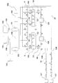
- FIG. 1 is a block diagram showing the configuration of an embodiment of a solid-state vaporization and supply system for a metal halide compound for forming a thin film of the present invention.
- a solid vaporization supply system 500 of the present embodiment includes an evaporation source container 100 for storing and evaporating a thin film forming metal halogen compound as an evaporation source, and an evaporation source container 100. And a connected buffer tank 101.
- reference numeral 102 indicates a raw material supply source 102 for supplying the metal halide compound A for forming a thin film to the evaporation raw material container 100.
- the metal halide compound A for forming a thin film may be supplied to the evaporation source container 100 in any of a liquid phase, a solid phase and a gas phase.
- Reference numeral 103 indicates a semiconductor processing facility 103, in which film formation by chemical vapor deposition (CVD) method, metalorganic chemical vapor deposition (MOCVD) method, atomic layer deposition (ALD) method is performed.
- the semiconductor processing equipment 103 is equipment (for example, a reaction chamber of a CVD apparatus) in which a substrate to be coated is arranged, and a desired thin film is formed on the substrate arranged in the semiconductor processing equipment 103.
- Reference numeral 104 indicates the heat exchanger 104.
- Reference numeral 105 indicates a temperature controller.
- Reference numeral 106 denotes a supply control unit 106 that controls the supply amount of the mixed gas G3 supplied from the buffer tank 101.
- Examples of the constituent elements of the supply control means 106 include a control valve, a flow meter, and a pressure gauge.
- Reference numeral 107 indicates a carrier gas supply means 107.
- Examples of the carrier gas G1 include hydrogen, helium, nitrogen, oxygen, argon, carbon monoxide, carbon dioxide, and the like.
- the carrier gas supply means 107 depicted on the upper side of the paper supplies nitrogen as the carrier gas G1
- the carrier gas supply means 107 depicted on the lower side of the paper supplies argon as the carrier gas G1.
- the semiconductor processing equipment 103 is a processing equipment used in the solid vaporization supply system 500, and is not a component of the solid vaporization supply system 500 of the present embodiment.
- the raw material supply source 102, the heat exchanger 104, the temperature controller 105, the supply control means 106, and the carrier gas supply means 107 are constituent elements that are appropriately and incidentally added to the solid vaporization supply system 500 of the present embodiment. is there.
- the respective constituent elements that exchange various gases are connected to each other via a gas pipe 34.
- the mixed gas G3 of the thin film forming metal halogen compound G2 evaporated in the evaporation source container 100 and the carrier gas G1 introduced into the evaporation source container 100 is supplied to the buffer tank 101. And a desired amount of the mixed gas G3 is supplied from the buffer tank 101 to the semiconductor processing facility 103. Therefore, according to the solid vaporization supply system 500 of the present embodiment, it is possible to realize the supply of the mixed gas G3 at a high flow rate.
- the evaporation raw material container 100 includes a container body 2, a lid body 4, a fastening member 6, and a joint member 8.
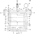
- FIG. 2 is a cross-sectional view schematically showing an evaporation raw material container used in one embodiment of the solid-state vaporization and supply system for a metal halide compound for forming a thin film of the present invention.
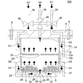
- FIG. 3 is a schematic diagram for explaining the gas flows of the carrier gas G1, the evaporated evaporation material (that is, the evaporated metal halide compound G2 for forming a thin film), and the mixed gas G3 in the evaporation material container shown in FIG. FIG.
- the container body 2 has a container wall 12, and is a substantial body part of the evaporation raw material container 100.
- the lid 4 is configured to be attachable to and detachable from the container body 2, and has a carrier gas inlet 16 for introducing the carrier gas G1 into the container body 2 and a mixed gas G3 of the evaporated thin film forming metal halogen compound G2 and the carrier gas G1. It has a mixed gas lead-out port 18 for leading the gas to the outside.
- the fastening member 6 is for fixing the container body 2 and the lid body 4.
- the fastening member 6 is a bolt inserted into a bolt insertion hole provided in the vessel body 2 and the lid body 4. Examples include a member and a nut member screwed and fastened to the bolt member.
- the joint member 8 connects the carrier gas inlet 16 and the mixed gas outlet 18 of the lid 4 to the valve 30, the pressure gauge 32, the flow meter (not shown), and other gas pipes. It is a thing.
- the container wall 12 of the container body 2 has a double wall structure 14 constituted by an inner wall member 12a and an outer wall member 12b. Then, the carrier gas G1 introduced from the carrier gas introduction port 16 is introduced into the container body 2 via the space between the inner wall member 12a and the outer wall member 12b of the double wall structure 14. With this configuration, when the container body 2 is heated from the outside, the carrier gas G1 introduced into the container body 2 can be simultaneously heated. Therefore, the heated carrier gas G1 can be brought into contact with the thin film-forming metal halogen compound S filled in the container body 2, and the thin film-forming metal halogen compound S is stably vaporized at a high flow rate. Can be made.
- the inside of the container body 2 can be heated via the inner wall member 12a of the container wall 12.
- the metal halide compound for forming a thin film filled in the container body 2 is indicated by a symbol S, and in FIG. 1, the metal halide compound for forming a thin film supplied from the raw material supply source 102 is shown. , Symbol A.
- the container wall 12 of the container body 2 is made of copper having a purity of 99 to 99.9999%, aluminum having a purity of 99 to 99.9999%, or titanium having a purity of 99 to 99.9999%.
- the container body 2, the lid 4, the fastening member 6, and the joint member 8 are each provided with a fluororesin coating 10.
- the surface of each of the container body 2, the lid 4, the fastening member 6, and the joint member 8 may be electrolytically polished. Further, the fluororesin coating 10 may be further applied to each surface subjected to electrolytic polishing. Therefore, the evaporation raw material container 100 has excellent corrosion resistance.
- the evaporation raw material container 100 includes the fluororesin coating 10 and/or the container body 2, the lid body 4, the fastening member 6, and the joint member 8, and particularly at the portions that do not substantially come into contact with the thin film forming metal halogen compound S. Or, since it is subjected to electrolytic polishing, it has extremely excellent corrosion resistance. Therefore, according to the solid vaporization supply system 500 (see FIG. 1) using the evaporation raw material container 100 configured as described above, particle contamination can be effectively reduced.
- the container wall 12 of the container body 2 is made of copper having a purity of 99 to 99.9999%, aluminum having a purity of 99 to 99.9999%, or titanium having a purity of 99 to 99.9999%, The thermal conductivity is excellent, and the inside of the container wall 12 can be heated well.
- the carrier gas G1 comes into contact with the outer wall of the container wall 12 so that the carrier gas G1 introduced into the container body 2 can be satisfactorily heated, The vaporization of the metal halide compound S for forming a thin film can be further promoted.
- the preheated carrier gas G1 into the evaporation source container 100, it is possible to effectively heat the inside of the container body 2 via the inner wall member 12a of the container wall 12.
- the term "purity” means the proportion (weight ratio) of the main components in the sample determined by quantitative analysis. If the purity of copper, aluminum or titanium forming the container wall 12 is less than 99%, it is not preferable in that the thermal conductivity of the container wall 12 is lowered. Further, if the purity of copper, aluminum or titanium constituting the container wall 12 exceeds 99.9999%, it is not preferable in that the strength of the container wall 12 is reduced.
- container wall 12 is a concept that includes not only the side wall but also the bottom wall. That is, when the evaporation raw material is put into the evaporation raw material container 100, it is preferable that the wall portion in contact with the evaporation raw material is the container wall.
- the carrier gas G1 is introduced into the container body 2 through the space between the inner wall member 12a and the outer wall member 12b at the bottom surface of the inner wall member 12a that constitutes the container wall 12.
- the container has an inlet 20.
- Reference numeral 30 in FIGS. 2 and 3 indicates a valve 30 for opening and closing the flow path of the evaporation raw material container 100.
- the carrier gas G1 can be introduced into the evaporation source container 100 (inside the container body 2) or the mixed gas G3 with the carrier gas G1 can be led out of the container body 2.
- the evaporation raw material container 100 can include two or more open/close valves.
- reference numeral 32 in FIG. 2 indicates a pressure gauge
- reference numeral 34 in FIG. 3 indicates a gas pipe.
- the material forming the fluororesin coating 10 is not particularly limited and may be any coatable fluororesin.
- a resin in which at least a part of hydrogen is replaced by fluorine can be used.
- examples thereof include polytetrafluoroethylene (trade name “Teflon” (registered trademark)) and the like. With such a material, it is possible to more favorably prevent impurities from mixing in the evaporation raw material.
- the thickness of the fluororesin coating 10 is not particularly limited, but for example, preferably 150 to 500 ⁇ m, more preferably 200 to 400 ⁇ m, and particularly preferably 250 to 350 ⁇ m. The thickness of about 300 ⁇ m is most preferable. If the thickness of the fluororesin coating 10 is less than the above lower limit value, sufficient corrosion resistance may not be obtained. If it exceeds the above upper limit, the layer may become too thick.
- the fluororesin coating 10 can be formed, for example, by vapor deposition, but the vapor deposition method can employ a conventionally known method and is not particularly limited.
- Fluorine resin coating 10 is preferably applied to all of the inner and outer surfaces of the container body 2, the inner and outer surfaces of the lid 4, the surface of the fastening member 6, and the surface of the joint member 8. That is, it is considered that the fluororesin coating 10 does not normally contact not only the surface (inner surface) contacting the carrier gas G1, the evaporated metal halide compound G2 for forming a thin film and the mixed gas G3, but also the above-mentioned gases. It is preferable that it is applied to the entire area including the surface (outer surface) of each member.
- the electrolytic polishing performed on the container body 2 or the like is preferably, for example, a polishing treatment performed under the following condition (i).
- a polishing treatment performed under the following condition (i).
- polishing conditions are a pressure of 20 to 60 kPa, a rotation speed of 350 rpm or less, and inorganic particles having an abrasive grain size of 0.020 to 0.10 ⁇ m are used as the abrasive grains.
- the current density is preferably 15 to 20 mA/cm 2 .
- the pH of the electrolytic solution is preferably 11 to 11.5.
- the rotation number of the polishing condition may be 50 to 350 rpm.
- Inorganic particles are used as the abrasive particles, and the inorganic particles are not particularly limited, but examples thereof include colloidal silica (Colloidal SiO 2 ).
- electrolytic polishing Whether or not electrolytic polishing has been performed can be confirmed, for example, by observing the surface with a microscope using both an electron microscope and an atomic force microscope (AFM).
- AFM atomic force microscope
- a method of inspecting the surface state by secondary electron mass spectrometry can be mentioned.
- the evaporation raw material container 100 has a container body 2, a lid body 4, a fastening member 6, and a joint member 8 each provided with a fluororesin coating 10 and/or electrolytic polishing. And may be chemically polished. Even with this structure, excellent corrosion resistance can be imparted. Further, when the fluororesin coating 10 is further applied after chemical polishing, the adhesion of the fluororesin coating 10 is further improved as in the case of performing electrolytic polishing. For example, contamination of moisture, oxygen, etc. at the interface with the fluororesin coating 10 is reduced, and the adhesion of the fluororesin coating 10 can be improved.
- Materials for the lid 4 and the fastening member 6 are not particularly limited, and examples thereof include aluminum, copper, titanium, nickel alloy, aluminum alloy, super stainless steel, and stainless steel.
- nickel alloys include, for example, Hastelloy, Inconel, and the like, and “Hastelloy” and “Inconel” are alloys containing Ni and Mo.
- Aluminum, copper, and titanium preferably have a purity of 99% or more, more preferably 99 to 99.9999%.
- the composition of “Hastelloy” can be appropriately determined, but specifically, Ni is 40 to 60 mass% and Mo is 30 to 50 mass %.
- Ni is 20 to 50 mass% and Mo is 70 to 50 mass %.
- Super stainless steel means Ni 17.00 to 19.50 mass%, Cr 19.00 to 21.00 mass%, Mo 5.50 to 6.50 mass%, and N 0.16 to 0 mass%. .24% by mass, Cu 0.50 to 1.00% by mass, further, C is 0.020% by mass or less, Si is 0.80% by mass or less, Mn is 1.00% by mass or less, and P is 0. A stainless steel having 0.030% by mass or less and S of 0.015% by mass or less and having further improved corrosion resistance.
- the container main body 2 further has one or more members having a maximum length in one direction of 1 to 30 mm and made of aluminum or copper. Good.
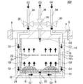
- the evaporation raw material container 200 shown in FIG. 4 further includes one or more spherical members 26 made of aluminum and having a diameter of 2 to 30 mm.
- the member (for example, the spherical member 26 in FIG. 4) included in the container body 2 is preferably a spherical member, an oblong member, a leaf-like member, a spiral member, or any other irregular member. In the case of a leaf-shaped member, its width is preferably about 1 to 2 cm.
- the length in the longitudinal direction is preferably about 1.5 to 3 cm. Also in the case of other irregularly shaped members, the length in the longitudinal direction is preferably about 1.5 to 3 cm.
- a member is made of aluminum, copper, or titanium, and may be made of the same material as the container wall 12, for example.
- the container wall 12 is made of copper having a purity of 99 to 99.9999%
- the spherical member 26 is preferably made of copper.
- FIG. 4 is a cross-sectional view schematically showing another example of the evaporation raw material container. 4, constituent elements similar to those of the evaporation raw material container 100 shown in FIGS. 2 and 3 are denoted by the same reference numerals, and description thereof may be omitted.
- the spherical member 26 made of aluminum as shown in FIG. 4 in the container body 2 for example, there is an advantage that the heat conduction of the compound in the container body 2 can be increased.
- the number of members such as the spherical member 26 shown in FIG. 4 arranged in the container body 2 is not particularly limited, but is preferably 10 to 20 for example.
- the evaporation raw material container 100 shown in FIGS. 2 and 3 may further include at least one plate-shaped shelf member 22 suspended in the container body 2.
- the metal halide compound S for forming a thin film may be arranged on such a shelf member 22.
- One or more through holes 24 are formed in the shelf member 22, and the gas flow of the carrier gas G1, the evaporated thin film-forming metal halide compound G2, and the mixed gas G3 in the container body 2 by the through holes 24. Is done.
- the shelf member 22 may be made of, for example, a porous body. Further, in the shelf member 22 formed of a porous body, one or more through holes 24 as shown in FIGS. 2 and 3 may not be formed. Gas flow of the carrier gas G1, the evaporated thin film forming metal halide compound G2, and the mixed gas G3 is performed in the container body 2 by the porous body forming the shelf member 22. Further, in the shelf member 22 formed of a porous body, the shelf member 22 itself has a function of a filter, and the particles generated in the container body 2 can be collected and removed by the shelf member 22. Further, as the porous body forming the shelf member 22, for example, ceramic can be cited.
- FIG. 5 is a cross-sectional view schematically showing still another example of the evaporation raw material container. 5, the same components as those of the evaporation source container 100 shown in FIGS. 2 and 3 are designated by the same reference numerals, and the description thereof may be omitted.
- the arrangement of the plurality of through holes 24 formed in the shelf member 22 is not particularly limited.
- the through holes 24 are evenly formed on the surface of the shelf member 22. Good.
- a plurality of through holes are sequentially formed so as to circulate around the shelf member, and the loci of the plurality of through holes are spiral. May be arranged so as to draw.
- FIG. 6 is a top view schematically showing the shelf member shown in FIG.
- the metal halide compound S for forming a thin film as an evaporation raw material filled in the evaporation raw material container 100 as shown in FIGS. 2 and 3 is preferably a compound represented by the following general formula (2).
- MXn (However, in the general formula (2), M is Al, Hf, Zr, Ta, W, Ga, La, Ce, Pr, Nd, Sm, Eu, Gd, Tb, Dy, Er, Tm, Yb and (Any element of Co is shown, X is a halogen element, and n is the number of X.)
- the halogen element of X is chlorine (Cl), aluminum chloride (AlCl 3 ), hafnium chloride (HfCl 4 ), zirconium chloride (ZrCl 4 ), chloride Tantalum (TaCl 5 ), tungsten pentachloride (WCl 5 ), tungsten hexachloride (WCl 6 ), gallium chloride (GaCl 3 ), lanthanum chloride (LaCl 3 ), cerium chloride (CeCl 3 ), praseodymium chloride (PrCl 3 ), Neodymium chloride (NdCl 3 ), samarium chloride (SmCl 3 ), europium chloride (EuCl 3 ), gadolinium chloride (GdCl 3 ), terbium chloride (TbCl 3 ), dysprosium chloride (DyCl 3 ), erbium chloride (Er
- the evaporation raw material container 100 can satisfactorily store even an evaporation raw material having a strong corrosive property such as the compound represented by the general formula (2), and the ratio of impurities present in the evaporation raw material is very high. Get smaller.
- the evaporation raw material container 100 is a container capable of contacting with a heating medium or a cooling medium that can be heated or cooled from the outside and holding the compound in the container in either a gas state or a solid state.
- the buffer tank 101 used in the solid vaporization supply system 500 shown in FIG. 1 is preferably made of a material having good thermal conductivity, for example. Further, as the buffer tank 101, for example, one in which SUS316 is electrolytically polished and 4N or 5N high-purity Al is bonded to the inner surface thereof can be mentioned. Further, the buffer tank 101 may be made of high-purity 4N or 5N Al and constitutes the main body of the buffer tank 101. For example, the buffer tank 101 is preferably made of a material having a thickness capable of withstanding a pressure of 49 N or more. As a method of using the buffer tank 101, for example, a mixed gas having a pressure of the carrier gas can be stored and used.
- a method of reducing pressure/flow rate fluctuations while generating a mixed gas in an evaporation raw material container can be used, or as another method, for example, a buffer tank 101 can be used. It is also possible to prepare two and use them by switching (that is, use a mixed gas like a cylinder). For example, the method of preparing and using two buffer tanks 101 is more preferable in that the supply pressure of the mixed gas can be kept constant while changing the flow rate of the mixed gas.
- the internal capacity of the buffer tank 101 is not particularly limited, but it is preferably, for example, 10 to 100 times the internal capacity of the container body of the evaporation raw material container. With such a configuration, the mixed gas stored in the buffer tank 101 can be stably supplied.
- the valve 30 disposed in a part of the gas flow path connecting the evaporation raw material container 100 and the buffer tank 101 has a CV value (water replacement) of 0.2 or more. It is preferred that In particular, this valve is more preferably a vacuum valve represented by a bellows valve. By providing such a valve, the mixed gas can be supplied more effectively. If the CV value (water replacement) is less than 0.2, the flow of a large flow rate of the mixed gas may be hindered, and the mixed gas may stay in the valve.
- the valve When the mixed gas stays in the valve, the heat of vaporization causes a temperature decrease, and the evaporation raw material (metal halide compound for thin film formation) is fixed in the valve and the valve may be closed.
- the CV value of the valve is preferably 0.2 or more, more preferably 0.6 or more, and particularly preferably 1.0 or more.
- the upper limit value of the CV value is not particularly limited, but may be 3.0 or 2.5, for example.
- Examples of the CV value valve as described above include a diaphragm, a ball valve, and a bellows valve. It is preferable that these valves do not depend on the valve function, body material, seat material, or temperature.
- the CV value of the valve is the value of water replacement measured by fully opening the valve and allowing water to flow.
- the flow rate of the fluid (water) flowing through the bubble is measured on the inflow side and the outflow side of the valve.
- a flow meter is used to measure the flow rate Q of the fluid flowing through the valve.
- pressure gauges are arranged in front of and behind the valve, and the pressure loss ⁇ P of the fluid passing through the valve is measured.
- the flow rate Q of the fluid and the pressure loss ⁇ P when passing through the valve will be measured according to the actual usage conditions.
- the measurement is performed so that the value is close to the actual usage condition.
- the flow rate Q of water can be determined from the specific gravity of the mixed gas and the specific gravity of water.
- the specific gravity of water is 1, the specific gravity of each evaporation material (for example, 1.40 to 1.68) and the flow rate of carrier gas is set to 500 cc/min, the flow rate Q of water is 300 cc/min. It becomes a degree.
- the CV value shall be measured under the condition of 15°C.
- the evaporation raw material container 100 configured as described above can extremely effectively reduce particle contamination in the solid vaporization supply system 500 shown in FIG. Therefore, the solid vaporization supply system 500 of the present embodiment can be effectively used for film formation by chemical vapor deposition (CVD) method, metalorganic chemical vapor deposition (MOCVD) method, atomic layer deposition (ALD) method.
- the atomic layer deposition (ALD) method is a method capable of forming a film thinner than the film formed by the chemical vapor deposition (CVD) method, and forms a very thin film of about several nm.
- the accuracy of the film is easily affected by the impurities contained in the evaporation raw material. Therefore, by using the solid vaporization supply system 500 of the present embodiment, the amount of particles (impurities) contained in the evaporation raw material can be made extremely small.
- the evaporation raw material container for the solid vaporization supply system can be manufactured, for example, as follows. First, the outer wall member of the container wall forming the container body is made of stainless steel or the like by a conventionally known method. Then, the inner wall member of the container wall constituting the container body is made of copper having a purity of 99 to 99.9999%, aluminum having a purity of 99 to 99.9999%, or titanium having a purity of 99 to 99.9999%. Then, the inner wall member is arranged inside the outer wall member to manufacture the container body. In addition, a lid body that is detachably attached to the container body is manufactured.
- a bolt insertion hole for arranging a fastening member is formed in the container body and the lid, and a bolt member and a nut member as a fastening member suitable for the bolt insertion hole are prepared. Further, various joint members to be arranged at the carrier gas inlet and the mixed gas outlet of the lid are prepared. In this way, each untreated member for forming the evaporation material container is obtained (preparing step).
- each member prepared is polished as necessary (polishing process). Specifically, the inner surface of each member is subjected to a polishing treatment to obtain each polished member. In the polishing treatment, it is preferable to perform electrolytic polishing treatment under the above-mentioned condition (i).
- the fluororesin coating can be formed by vapor deposition.
- the fluororesin coating when the electrolytic polishing treatment under the above-mentioned condition (i) is performed, the fluororesin coating may not be applied.
- each member is assembled to make a container for evaporation raw material (assembly process).
- the evaporation raw material container for the solid vaporization supply system can be manufactured.
- a SUS tank is manufactured.
- an instrument made of SUS that can measure the pressure above and below is attached, and a pressure valve provided with an H-type purge gas line is connected to the film forming chamber side.
- a three-way valve is attached to the supply line on the cylinder side of the SUS tank.
- the supply gas is sent to a tank made of SUS at a pressure equal to or higher than the saturated vapor pressure, and the temperature on the supply side of the buffer tank by the external heating method is 200° C. to 250° C.
- the inside of the buffer tank is preferably subjected to an inner surface treatment with a material containing aluminum and/or Hastelloy after the inner surface is electrolytically polished.
- Such inner surface treatment can be performed by joining or welding.
- the solid vaporization supply system of the present invention can be manufactured by connecting the produced evaporation material container and the buffer tank with a gas pipe. It should be noted that it is preferable to appropriately install instruments such as an on-off valve, a control valve, a flow meter, and a pressure gauge in the gas pipe connecting the evaporation raw material container and the buffer tank.
- a vacuum valve having a CV value (water substitution) of 0.2 or more can be preferably used as a valve arranged in a part of a gas flow path connecting the evaporation raw material container and the buffer tank.
- the carrier gas inlet 16 (see FIG. 2) of the evaporation source container 100 is connected to the carrier gas supply means 107.
- the mutual connection is performed by the gas pipe 34, and it is preferable to appropriately provide an instrument such as an on-off valve, a control valve, a flow meter, and a pressure gauge.
- the mixed gas outlet 18 (see FIG. 2) of the evaporation raw material container 100 is connected to the buffer tank 101.
- the evaporation raw material container 100 is connected to a raw material supply source 102 for supplying the thin film forming metal halogen compound A to the evaporation raw material container 100.
- These connections can also be made by the gas pipe 34.
- the supply control means 106 for controlling the supply amount and the like of the mixed gas G3 supplied to the buffer tank 101 is connected, and the semiconductor processing equipment 103 is connected via this supply control means 106.
- the metal halide compound A for forming a thin film as an evaporation material is charged from the material supply source 102 into the evaporation material container 100. Then, the evaporation raw material container 100 is closed.
- the carrier gas G1 is introduced into the evaporation material container 100 from the carrier gas supply means 107. Then, the evaporation raw material (the evaporated metal halogen compound G2 for forming a thin film) and the carrier gas G1 mixed in the evaporation raw material container 100 are mixed, and the mixed gas G3 is derived from the mixed gas outlet 18 (see FIG. 2). To be done.
- the evaporated raw material is evaporated (vaporized) by heating or the like to become a raw material gas.
- the carrier gas G1 is introduced, as shown in FIGS. 2 and 3, the container wall 12 of the container body 2 is heated to heat the thin film forming metal halide compound S in the container body 2.
- the carrier gas G1 is introduced from the carrier gas introduction port 16 of the lid body 4, and is passed through between the inner wall member 12a and the outer wall member 12b of the double wall structure 14 of the heated container wall 12, and the heated carrier gas G1 is introduced into the container body 2. Then, the evaporated metal halide compound G2 for forming a thin film and the carrier gas G1 are mixed to prepare a mixed gas G3. With this structure, the heated carrier gas G1 can be brought into contact with the thin film-forming metal halogen compound S, and the thin film-forming metal halogen compound S can be vaporized stably and at a high flow rate. it can.
- the mixed gas G3 derived from the evaporation raw material container 100 is stored in the buffer tank 101 via the gas pipe 34.
- the buffer tank 101 For example, two or more buffer tanks 101 are provided, and a predetermined amount of mixed gas G3 is stored in the first buffer tank 101, and then the mixed gas G3 is sequentially stored in the second and subsequent buffer tanks 101. Is preferred.
- the mixed gas G3 as a film forming gas is supplied from the buffer tank 101 to the semiconductor processing equipment 103, and in the semiconductor processing equipment 103, a chemical vapor deposition (CVD) method, a metal organic chemical vapor deposition (MOCVD) method, Film formation by an atomic layer deposition (ALD) method or the like is started.
- the supply of the mixed gas G3 to the semiconductor processing equipment 103 is adjusted by the supply control means 106 to a predetermined pressure and flow rate.
- the evaporation material container 100 has excellent corrosion resistance, and the ratio of impurities derived from the container in the evaporation material is extremely small. Therefore, the high-purity mixed gas G3 can be supplied to the semiconductor processing facility 103.
- the container wall of the container body of the evaporation source container was made of the materials shown in "Material” and “Purity (%)" of "Container Wall” in Tables 1 and 2. Further, the surfaces of the container body, the lid, the fastening member, and the joint member were polished under the following polishing conditions (i). Then, a fluororesin coating was applied on the surface of each member that had been subjected to the polishing treatment.
- the fluororesin coating was performed by depositing polytetrafluoroethylene (Teflon) using an apparatus that performs vapor deposition by electron irradiation vacuum vapor deposition.
- the pressure was 31.35 kPa
- the rotation speed was 300 rpm
- colloidal silica having an abrasive grain size of 0.07 ⁇ m was used as the abrasive grains.
- a buffer tank by the following method.
- a tank made of SUS was manufactured.
- the prepared SUS tank was equipped with instruments made of SUS capable of measuring pressure above and below, and a pressure valve provided with an H-type purge gas line was connected to the film forming chamber side.
- a three-way valve was attached to the supply line on the cylinder side of the SUS tank.
- the supply gas was sent to the SUS tank at a pressure equal to or higher than the saturated vapor pressure, and the temperature of the supply side of the buffer tank was 200°C to 250°C and the temperature of the film forming chamber was 300°C by the external heating method.
- the pressure gauge near the film forming chamber was designed to maintain a constant supply pressure while maintaining a temperature of up to 400°C.
- the capacities of the buffer tanks manufactured in each of the examples and comparative examples are shown in the "buffer tank capacity (L)" column of Tables 1 to 6.
- a solid vaporization supply system was created by connecting the evaporation raw material container and the buffer tank with gas piping.
- the gas pipe serves as a gas flow path through which the mixed gas generated by the evaporation raw material container passes.
- a valve having a CV value (water substitution) of 1.5 was arranged in a part of the gas pipe connecting the evaporation raw material container and the buffer tank, and the mixed gas was supplied through such a valve. ..
- Example 16 to 30 containers for evaporating raw materials were produced in the same manner as in Examples 1 to 15 except that the fluororesin coating was not applied. That is, in the evaporation raw material containers of Examples 16 to 30, the surfaces of the container body, the lid, the fastening member, and the joint member were only subjected to the polishing treatment under the above polishing conditions (i). In each of Examples 16 to 30, the container wall of the container body of the evaporation raw material container was made of the materials shown in "Material” and “Purity (%)" of "Container wall” in Table 3.
- a buffer tank was manufactured by the method described above, and the evaporation raw material container and the buffer tank were connected by a gas pipe to manufacture a solid vaporization supply system.
- a valve having a CV value (water substitution) of 1.5 was arranged in a part of the gas pipe connecting the evaporation raw material container and the buffer tank, and the mixed gas was supplied through such a valve. ..
- the metal halogen compound for thin film formation shown in the column of “raw material (metal halogen compound)” in Tables 1 to 3 is stored, and a carrier gas is supplied into the container body to form an evaporated thin film.
- a mixed gas was produced by mixing the metal halogen compound for use with a carrier gas.
- the generated mixed gas was once stored in a buffer tank, and the mixed gas stored in this buffer tank was used to perform film formation by an atomic layer deposition (ALD) method.
- Tables 4 to 6 show the compositions of ALD films formed by the atomic layer deposition (ALD) method.
- the amounts of impurities (12 elemental elements shown in Tables 4 to 6) in the evaporated raw material after film formation were measured by ICPMS (inductively coupled plasma mass spectrometry).
- ICPMS inductively coupled plasma mass spectrometry
- Tables 4 to 6 show the flow rates of the reaction gas used for forming the ALD film in each of the examples and comparative examples.
- the flow rates of the reaction gases in Tables 1 to 3 indicate the flow rates of the reaction gas generated by the evaporation raw material container.
- the amount of impurities was measured by the following method. First, after the film formation, the residue of the evaporation raw material remaining in the container body of the evaporation raw material container was recovered. Next, the recovered material was dissolved in a predetermined amount using aqua regia in an ICPMS (inductively coupled high frequency plasma mass spectrometry) apparatus. Then, this was heated to 120° C. on a hot plate to evaporate to dryness. Then, the evaporated sample was diluted to obtain a measurement sample. After that, metal impurities in the measurement sample were measured by the above analyzer.
- ICPMS inductively coupled high frequency plasma mass spectrometry
- the surface roughness of the inner surface of the container body 2 was measured before and after the film formation by an AFM (atomic force microscope) analyzer (manufactured by HORIBA). This surface roughness was measured several times and the average value was calculated. A value was calculated by dividing A by B, where A is the surface roughness before film formation and B is the surface roughness before film formation. The calculated "A/B" values are shown in the "Internal surface roughness" column of Tables 4 to 6.
- the growth rate (GPC; Growth Per Cycle) was measured. Specifically, during the above-described film formation, the valve is opened/closed once every 0.2 seconds to introduce the mixed gas containing the evaporation material into the film formation chamber. One cycle of valve opening and closing is 0.2 seconds, and the film thickness formed on an 8-inch silicon wafer is measured to calculate the film growth rate per unit time (1 cycle).
- Example 31 to 45 evaporation raw material containers were manufactured by the same method as in Examples 1 to 15.
- Example 31 the same evaporation source container as in Example 1 was produced, and thereafter, in Example 32 and subsequent examples, the evaporation source containers corresponding to Example 2 and subsequent examples were also produced.
- a buffer tank was manufactured by the method described above, and the evaporation raw material container and the buffer tank were connected by a gas pipe to manufacture a solid vaporization supply system.
- a valve having a CV value (water substitution) of 1.5 was arranged in a part of the gas pipe connecting the evaporation raw material container and the buffer tank, and the mixed gas was supplied through such a valve. ..
- the capacity of the buffer tank is as shown in Table 7. Then, a film was formed by an atomic layer deposition (ALD) method in the same manner as in Examples 1 to 15. In Examples 31 to 45, a mixed gas was generated without filling a filling material such as a spherical member in the evaporation raw material container.
- ALD atomic layer deposition
- Comparative Examples 17 to 32 evaporation material containers were produced by the same method as in Comparative Examples 1 to 16.
- Comparative Example 17 an evaporation source container similar to that of Comparative Example 1 was produced, and hereinafter, also in Comparative Example 18 and later, the evaporation source containers corresponding to Comparative Example 2 and later were produced.
- Comparative Examples 17 to 32 atomic layer deposition was performed by using a vaporization raw material container and a gas pipe connected to the solid vaporization supply system without using a buffer tank and directly supplying a mixed gas from the vaporization raw material container.
- a film was formed by the (ALD) method.
- Tables 7 and 8 show the compositions of ALD films formed by the atomic layer deposition (ALD) method in Examples 31 to 45 and Comparative Examples 17 to 32. Further, the amounts of impurities (12 elemental elements shown in Tables 7 and 8) in the evaporated raw material after film formation were measured by ICPMS (inductively coupled plasma mass spectrometry). In the column of "Before film formation” in Table 7, the amount of impurities (12 kinds of elements shown in Tables 7 and 8) in the evaporation raw material before film formation is described. Tables 7 and 8 show the flow rates of the reaction gas in each Example and Comparative Example. In addition, the “internal surface roughness” and the “growth rate” were measured by the same method as described above. The results are shown in Tables 7 and 8.
- the solid vaporization supply systems of Examples 1 to 45 have smaller amounts of impurities than the solid vaporization supply systems of Comparative Examples 1 to 32. Further, in the evaporation raw material containers of the solid vaporization supply systems of Examples 1 to 45, the value of “A/B” of “internal surface roughness” was close to 1, and the difference in surface roughness before and after film formation was small. It turns out to be small. Here, the fact that the difference in the surface roughness is small means that the degree of corrosion by the evaporating raw material was small, and it can be seen that the corrosion resistance is high.
- the solid vaporization supply systems of Examples 1 to 45 (especially, the evaporation raw material container) have excellent corrosion resistance. Further, since the solid vaporization supply systems of Examples 1 to 45 are provided with the buffer tanks on the downstream side of the evaporation raw material container, the mixed gas containing the evaporation raw materials can be stably supplied at a high flow rate, It was possible to realize an excellent growth rate in the growth of the ALD film.
- the solid vaporization supply system of a metal halide compound for forming a thin film of the present invention is used for film formation by a chemical vapor deposition (CVD) method, a metal organic chemical vapor deposition (MOCVD) method, an atomic layer deposition (ALD) method.
- CVD chemical vapor deposition
- MOCVD metal organic chemical vapor deposition
- ALD atomic layer deposition
Landscapes
- Chemical & Material Sciences (AREA)
- Chemical Kinetics & Catalysis (AREA)
- Engineering & Computer Science (AREA)
- Materials Engineering (AREA)
- Metallurgy (AREA)
- Organic Chemistry (AREA)
- General Chemical & Material Sciences (AREA)
- Mechanical Engineering (AREA)
- Inorganic Chemistry (AREA)
- Electrochemistry (AREA)
- Chemical Vapour Deposition (AREA)
Abstract
パーティクル汚染を低減することが可能な薄膜形成用金属ハロゲン化合物の固体気化供給システムを提供する。薄膜形成用金属ハロゲン化合物を貯留し且つ蒸発させるための蒸発原料用容器100と、蒸発原料用容器100に接続されたバッファタンク101と、を備え、蒸発原料用容器100は、容器壁を有する容器本体と、蓋体と、締結部材と、継手部材とを備え、容器壁は、内壁部材及び外壁部材によって構成された二重壁構造を有し、キャリアガスが二重壁構造の間を経由して容器本体内に導入されるように構成され、容器壁が、純度99~99.9999%の銅、純度99~99.9996%のアルミニウム、又は純度99~99.9999%のチタンから構成され、容器本体、蓋体、締結部材、及び継手部材のそれぞれには、フッ素樹脂コーティング及び/又は電解研磨が施されている。
Description
本発明は、薄膜形成用金属ハロゲン化合物の固体気化供給システムに関する。更に詳しくは、パーティクル汚染を低減することができ、且つ高流量の供給を実現することが可能な薄膜形成用金属ハロゲン化合物の固体気化供給システムに関する。
従来、例えば化学気相成長(CVD)法において蒸発原料を貯留するための容器として蒸発原料用容器が知られており、そして、この蒸発原料用容器の蒸発器本体を構成する材料として、ステンレス鋼などが報告されている(特許文献1参照)。
しかし、特許文献1に記載のような蒸発器は、容器壁にステンレス鋼を採用しており、このステンレス鋼製の容器壁は、熱伝導性が良いものであるが、耐腐食性が十分でないという問題があった。例えば、ステンレス鋼は、耐腐食性を有するものであるが、蒸発原料と触れることで僅かに腐食し、極微量の不純物が蒸発原料中に混ざることがあった。また、ハステロイなどのその他の材料であっても、ステンレス鋼と同様に極微量の不純物が蒸発原料中に混ざることがあった。蒸発原料中に上述したような不純物が混ざると、蒸発器により気化された原料がパーティクル(微小粒子)によって汚染された状態で、半導体処理設備等に供給されることとなる。
また、近年、より反応性の高い蒸発原料として金属ハロゲン化合物の使用が検討されている。このような金属ハロゲン化合物は、水分と反応して塩化水素等の酸性ガスを発生するため、このような塩酸ガスにより蒸発原料用容器の腐食がより顕著になるという問題があった。
一方で、最近では、半導体製品の更なる高性能化が求められるようになり、その結果、より高純度の蒸発原料(即ち、不純物の割合がより小さい蒸発原料)であることが要求されてきている。また、原子層堆積(ALD)法による成膜を行う場合、その膜には、原子レベルでの無欠陥や均一性が求められるため、蒸発原料に含まれる不純物の量を極限まで少なくする必要がある。このため、蒸発原料用容器の腐食に対する対策は更に重要になっている。
本発明は、このような従来技術の有する問題点に鑑みてなされたものである。本発明は、パーティクル汚染を低減することができ、且つ高流量の供給を実現することが可能な薄膜形成用金属ハロゲン化合物の固体気化供給システムを提供するものである。
本発明によれば、以下に示す薄膜形成用金属ハロゲン化合物の固体気化供給システムが提供される。
[1] 蒸発原料としての薄膜形成用金属ハロゲン化合物を貯留し且つ蒸発させるための蒸発原料用容器と、前記蒸発原料用容器に接続されたバッファタンクと、を備えた薄膜形成用金属ハロゲン化合物の固体気化供給システムであって、
前記蒸発原料用容器は、
容器壁を有する容器本体と、
前記容器本体に着脱自在に構成され、前記容器本体内にキャリアガスを導入するキャリアガス導入口及び蒸発した前記薄膜形成用金属ハロゲン化合物と前記キャリアガスとの混合ガスを外部に導出する混合ガス導出口を有する蓋体と、
前記容器本体と前記蓋体とを固定する締結部材と、
前記蓋体の前記キャリアガス導入口及び前記混合ガス導出口に配設された継手部材と、を備え、
前記容器本体の前記容器壁は、内壁部材及び外壁部材によって構成された二重壁構造を有し、前記キャリアガス導入口から導入された前記キャリアガスが、前記二重壁構造の前記内壁部材と前記外壁部材の間を経由して前記容器本体内に導入されるように構成され、且つ、
前記容器本体の前記容器壁が、純度99~99.9999%の銅、純度99~99.9999%のアルミニウム、又は純度99~99.9999%のチタンから構成され、
前記容器本体、前記蓋体、前記締結部材、及び前記継手部材のそれぞれには、フッ素樹脂コーティングが施されている、及び/又は、それぞれの表面に電解研磨が施されている、固体気化供給システム。
前記蒸発原料用容器は、
容器壁を有する容器本体と、
前記容器本体に着脱自在に構成され、前記容器本体内にキャリアガスを導入するキャリアガス導入口及び蒸発した前記薄膜形成用金属ハロゲン化合物と前記キャリアガスとの混合ガスを外部に導出する混合ガス導出口を有する蓋体と、
前記容器本体と前記蓋体とを固定する締結部材と、
前記蓋体の前記キャリアガス導入口及び前記混合ガス導出口に配設された継手部材と、を備え、
前記容器本体の前記容器壁は、内壁部材及び外壁部材によって構成された二重壁構造を有し、前記キャリアガス導入口から導入された前記キャリアガスが、前記二重壁構造の前記内壁部材と前記外壁部材の間を経由して前記容器本体内に導入されるように構成され、且つ、
前記容器本体の前記容器壁が、純度99~99.9999%の銅、純度99~99.9999%のアルミニウム、又は純度99~99.9999%のチタンから構成され、
前記容器本体、前記蓋体、前記締結部材、及び前記継手部材のそれぞれには、フッ素樹脂コーティングが施されている、及び/又は、それぞれの表面に電解研磨が施されている、固体気化供給システム。
[2] 前記蒸発原料用容器と前記バッファタンクとを接続するガス流路の一部に配設されたバルブを更に備え、
前記バルブは、CV値(水置換)が0.2以上の真空バルブである、前記[1]に記載の固体気化供給システム。
前記バルブは、CV値(水置換)が0.2以上の真空バルブである、前記[1]に記載の固体気化供給システム。
[3] 前記容器壁を構成する前記内壁部材の底面部に、前記内壁部材と前記外壁部材の間を経由した前記キャリアガスが前記容器本体に導入される容器内導入口を有する、前記[1]又は[2]に記載の固体気化供給システム。
[4] 前記締結部材が、前記容器本体及び前記蓋体に設けられたボルト挿入孔に挿入されたボルト部材及び前記ボルト部材に螺合して締結したナット部材からなる、前記[1]~[3]のいずれかに記載の固体気化供給システム。
[5] 前記容器本体内に懸架された、少なくとも1つの板状の棚部材を更に有する、前記[1]~[4]のいずれかに記載の固体気化供給システム。
[6] 前記棚部材の少なくとも1つは、複数の貫通孔が形成されたシャワーヘッド構造を有する、前記[5]に記載の固体気化供給システム。
[7] 前記棚部材の少なくとも1つは、多孔質体によって構成されている、前記[5]に記載の固体気化供給システム。
[8] 前記容器本体内に、一の方向における最大長さが1~30mmで、アルミニウム製又は銅製の、一以上の球状、長球状、葉状、螺旋状、又はその他不定形状の部材を更に有する、前記[1]~[7]のいずれかに記載の固体気化供給システム。
[9] 前記蒸発原料としての前記薄膜形成用金属ハロゲン化合物が、下記一般式(1)で表される化合物である、前記[1]~[8]のいずれかに記載の固体気化供給システム。
一般式(1):MXn
(但し、前記一般式(1)において、Mは、Al、Hf、Zr、Ta、W、Ga、La、Ce、Pr、Nd、Sm、Eu、Gd、Tb、Dy、Er、Tm、Yb及びCoのいずれかの元素を示す。Xは、ハロゲン元素を示す。nは、Xの数である。)
一般式(1):MXn
(但し、前記一般式(1)において、Mは、Al、Hf、Zr、Ta、W、Ga、La、Ce、Pr、Nd、Sm、Eu、Gd、Tb、Dy、Er、Tm、Yb及びCoのいずれかの元素を示す。Xは、ハロゲン元素を示す。nは、Xの数である。)
[10] 化学気相成長法による成膜に用いられる、前記[1]~[9]のいずれかに記載の固体気化供給システム。
[11] 原子層堆積法による成膜に用いられる、前記[1]~[10]のいずれかに記載の固体気化供給システム。
[12] 前記蒸発原料用容器の前記容器本体内に前記キャリアガスを供給するキャリアガス供給手段を更に備える、前記[1]~[11]のいずれかに記載の固体気化供給システム。
本発明の薄膜形成用金属ハロゲン化合物の固体気化供給システムは、パーティクル汚染を低減することができ、且つ高流量の供給を実現することができるという効果を奏する。このため、本発明の薄膜形成用金属ハロゲン化合物の固体気化供給システムによれば、より高純度の蒸発原料(即ち、蒸発した薄膜形成用金属ハロゲン化合物とキャリアガスとの混合ガス)を高流量で供給することができる。
以下、本発明を実施するための形態について説明するが、本発明は以下の実施の形態に限定されるものではない。即ち、本発明の趣旨を逸脱しない範囲で、当業者の通常の知識に基づいて、以下の実施の形態に対し適宜変更、改良等が加えられたものも本発明の範囲に属することが理解されるべきである。
[1]薄膜形成用金属ハロゲン化合物の固体気化供給システム:
本発明の薄膜形成用金属ハロゲン化合物の固体気化供給システムの一の実施形態は、図1に示すような固体気化供給システム500である。以下、本実施形態の薄膜形成用金属ハロゲン化合物の固体気化供給システムを、単に「固体気化供給システム」ということがある。図1は、本発明の薄膜形成用金属ハロゲン化合物の固体気化供給システムの一の実施形態の構成を示すブロック図である。
本発明の薄膜形成用金属ハロゲン化合物の固体気化供給システムの一の実施形態は、図1に示すような固体気化供給システム500である。以下、本実施形態の薄膜形成用金属ハロゲン化合物の固体気化供給システムを、単に「固体気化供給システム」ということがある。図1は、本発明の薄膜形成用金属ハロゲン化合物の固体気化供給システムの一の実施形態の構成を示すブロック図である。
図1に示すように、本実施形態の固体気化供給システム500は、蒸発原料としての薄膜形成用金属ハロゲン化合物を貯留し且つ蒸発させるための蒸発原料用容器100と、この蒸発原料用容器100に接続されたバッファタンク101と、を備えたものである。図1において、符号102は、薄膜形成用金属ハロゲン化合物Aを蒸発原料用容器100に供給するための原料供給源102を示す。薄膜形成用金属ハロゲン化合物Aの蒸発原料用容器100への供給は、液相、固相、気相のいずれの状態で行われてもよい。符号103は、半導体処理設備103を示し、この半導体処理設備103において、化学気相成長(CVD)法、有機金属化学気相成長(MOCVD)法、原子層堆積(ALD)法による成膜が行われる。即ち、半導体処理設備103は、被膜対象である基板が配置される設備(例えば、CVD装置の反応室)であり、この半導体処理設備103内に配置された基板上に所望の薄膜を形成する。符号104は、熱交換器104を示す。符号105は、温度コントローラを示す。符号106は、バッファタンク101から供給される混合ガスG3の供給量等を制御する供給制御手段106を示す。供給制御手段106を構成する要素としては、例えば、コントロールバルブ、流量計、及び圧力計などを挙げることができる。符号107は、キャリアガス供給手段107を示す。キャリアガスG1としては、例えば、水素、ヘリウム、窒素、酸素、アルゴン、一酸化炭素、二酸化炭素などを挙げることができる。なお、図1において、紙面の上段に描かれたキャリアガス供給手段107が、キャリアガスG1として窒素を供給し、紙面の下段に描かれたキャリアガス供給手段107が、キャリアガスG1としてアルゴンを供給する例を示している。なお、半導体処理設備103は、固体気化供給システム500に用いられる処理設備であり、本実施形態の固体気化供給システム500の構成要素ではない。また、原料供給源102、熱交換器104、温度コントローラ105、供給制御手段106及びキャリアガス供給手段107は、本実施形態の固体気化供給システム500に対して付帯的に適宜付与される構成要素である。図1において、各種ガスの授受を行う各構成要素についてはガス配管34を介して相互に接続されている。
本実施形態の固体気化供給システム500は、蒸発原料用容器100にて蒸発した薄膜形成用金属ハロゲン化合物G2と蒸発原料用容器100に導入されたキャリアガスG1との混合ガスG3を、バッファタンク101に貯留し、このバッファタンク101から適宜所望量の混合ガスG3を半導体処理設備103に供給するものである。このため、本実施形態の固体気化供給システム500によれば、高流量の混合ガスG3の供給を実現することができる。
蒸発原料用容器100は、図2及び図3に示すように、容器本体2、蓋体4、締結部材6、及び継手部材8を備えたものである。ここで、図2は、本発明の薄膜形成用金属ハロゲン化合物の固体気化供給システムの一の実施形態に用いられる蒸発原料用容器を模式的に示す断面図である。図3は、図2に示す蒸発原料用容器における、キャリアガスG1、蒸発した蒸発原料(即ち、蒸発した薄膜形成用金属ハロゲン化合物G2)、及び混合ガスG3のガス流れを説明するための模式的な断面図である。
容器本体2は、容器壁12を有するものであり、蒸発原料用容器100における実質的な本体部分である。蓋体4は、容器本体2に着脱自在に構成され、容器本体2内にキャリアガスG1を導入するキャリアガス導入口16及び蒸発した薄膜形成用金属ハロゲン化合物G2とキャリアガスG1との混合ガスG3を外部に導出する混合ガス導出口18を有する。締結部材6は、容器本体2と蓋体4とを固定するためのものであり、例えば、締結部材6としては、容器本体2と蓋体4とに設けられたボルト挿入孔に挿入されたボルト部材及びこのボルト部材に螺合して締結したナット部材を挙げることができる。継手部材8は、蓋体4のキャリアガス導入口16及び混合ガス導出口18と、バルブ30、圧力計32、流量計(図示せず)、その他のガス配管等とを相互に接続するためのものである。
容器本体2の容器壁12は、内壁部材12a及び外壁部材12bによって構成された二重壁構造14を有する。そして、キャリアガス導入口16から導入されたキャリアガスG1は、二重壁構造14の内壁部材12aと外壁部材12bの間を経由して容器本体2内に導入される。このように構成することによって、容器本体2を外部から加熱した際に、容器本体2内に導入されるキャリアガスG1も同時に加熱することができる。このため、容器本体2内に充填された薄膜形成用金属ハロゲン化合物Sに対して、加熱されたキャリアガスG1を接触させることができ、薄膜形成用金属ハロゲン化合物Sを安定的且つ高流量で気化させることができる。また、予め加熱されたキャリアガスG1を蒸発原料用容器100に導入することにより、容器壁12の内壁部材12aを介して容器本体2内を加熱することもできる。図2及び図3において、容器本体2内に充填された薄膜形成用金属ハロゲン化合物を、符号Sで示し、図1において、原料供給源102から供給される充填前の薄膜形成用金属ハロゲン化合物を、符号Aで示している。
蒸発原料用容器100は、容器本体2の容器壁12が、純度99~99.9999%の銅、純度99~99.9999%のアルミニウム、又は純度99~99.9999%のチタンから構成されている。また、容器本体2、蓋体4、締結部材6、及び継手部材8のそれぞれには、フッ素樹脂コーティング10が施されている。なお、容器本体2、蓋体4、締結部材6、及び継手部材8のそれぞれには、フッ素樹脂コーティング10に代えて、それぞれの表面に電解研磨が施されていてもよい。また、電解研磨が施された各表面に、更に、フッ素樹脂コーティング10が施されていてもよい。このため、蒸発原料用容器100は、優れた耐腐食性を有する。特に、金属ハロゲン化合物は、水分と反応して塩化水素等の酸性ガスを発生するため、従来の蒸発原料用容器では、蒸発原料用容器の内部だけでなく、容器本体や蓋体の表面、ボルト部材やナット部材等の締結部材、及び継手部材等にも腐食を生じることがある。蒸発原料用容器100は、容器本体2、蓋体4、締結部材6、及び継手部材8のそれぞれ、特に、実質的に薄膜形成用金属ハロゲン化合物Sと接触しない箇所についてもフッ素樹脂コーティング10及び/又は電解研磨が施されているため、極めて優れた耐腐食性を有する。このため、このように構成された蒸発原料用容器100を用いた固体気化供給システム500(図1参照)によれば、パーティクル汚染を有効に低減することができる。
上述したように容器本体2の容器壁12が、純度99~99.9999%の銅、純度99~99.9999%のアルミニウム、又は純度99~99.9999%のチタンから構成されているため、熱伝導性に優れ、容器壁12内部を良好に加熱することができる。特に、容器本体2内にキャリアガスG1を導入する前に、容器壁12の外壁にキャリアガスG1が接触することにより、容器本体2内に導入するキャリアガスG1を良好に加熱することができ、薄膜形成用金属ハロゲン化合物Sの気化をより促進させることができる。また、予め加熱されたキャリアガスG1を蒸発原料用容器100に導入することにより、容器壁12の内壁部材12aを介して容器本体2内を有効に加熱することもできる。なお、「純度」とは、定量分析により決定した主成分の試料中に占める割合(重量比)のことを意味する。容器壁12を構成する銅、アルミニウム又はチタンの純度が99%未満であると、容器壁12の熱伝導性が低下する点において好ましくない。また、容器壁12を構成する銅、アルミニウム又はチタンの純度が99.9999%を超えると、容器壁12の強度が低下する点において好ましくない。
なお、「容器壁12」は、側壁だけでなく底壁も含む概念である。つまり、蒸発原料が蒸発原料用容器100内に投入された際に、この蒸発原料が接する壁部分はこの容器壁ということがよい。
図2及び図3に示す蒸発原料用容器100においては、容器壁12を構成する内壁部材12aの底面部に、内壁部材12aと外壁部材12bの間を経由したキャリアガスG1が容器本体2に導入される容器内導入口20を有する。
図2及び図3における符号30は、蒸発原料用容器100の流路の開閉を行うバルブ30を示している。このバルブ30を開くことで、蒸発原料用容器100(容器本体2内)にキャリアガスG1を導入したり、キャリアガスG1との混合ガスG3を容器本体2外に導出したりすることができる。このように、蒸発原料用容器100は、2本以上の開閉バルブを備えることができる。また、図2における符号32は圧力計を示し、図3における符号34はガス配管を示している。
フッ素樹脂コーティング10を構成する材料は、特に制限はなく、コーティング可能なフッ素樹脂であれば良いが、例えば、少なくとも一部の水素がフッ素に置換された樹脂などを挙げることができ、具体的には、ポリテトラフルオロエチレン(商品名「テフロン」(登録商標))などを挙げることができる。このような材料であると、不純物が蒸発原料中に混ざることを更に良好に抑制することができる。
フッ素樹脂コーティング10の厚さは、特に制限はないが、例えば、150~500μmとすることが好ましく、200~400μmとすることが更に好ましく、250~350μmとすることが特に好ましい。なお、300μm程度が最も好ましい。フッ素樹脂コーティング10の厚さが上記下限値未満であると、十分な耐腐食性が得られないおそれがある。上記上限値超であると、層が厚くなりすぎてしまうおそれがある。
フッ素樹脂コーティング10は、例えば蒸着により形成することができるが、その蒸着方法は従来公知の方法を採用することができ特に制限はない。
フッ素樹脂コーティング10は、容器本体2の内面及び外面、蓋体4の内面及び外面、締結部材6の表面、及び継手部材8の表面の全てに施されていることが好ましい。即ち、フッ素樹脂コーティング10は、キャリアガスG1、蒸発した薄膜形成用金属ハロゲン化合物G2及び混合ガスG3と接触する面(内面)だけでなく、通常、前述した各ガスと接触しないと考えられている各部材の表面(外面)を含めた全域に対して施されていることが好ましい。
容器本体2等に施される電解研磨については、例えば、下記の条件(i)によって施された研磨処理であることが好ましい。なお、このような研磨処理を行うことで、フッ素樹脂コーティング10を更に施す場合において、フッ素樹脂コーティング10の密着性が更に良くなる。
条件(i):
直径250~350mmの電極を用い、電流密度を28.5mA/cm2以下、電解溶液の濃度を15~30質量%、液流量を1~8L/分、電解溶液のpHをアルカリ性とし、更に、研磨条件としては、圧力20~60kPa、回転数350rpm以下とし、砥粒として砥粒径0.020~0.10μmの無機粒子を用いる。
直径250~350mmの電極を用い、電流密度を28.5mA/cm2以下、電解溶液の濃度を15~30質量%、液流量を1~8L/分、電解溶液のpHをアルカリ性とし、更に、研磨条件としては、圧力20~60kPa、回転数350rpm以下とし、砥粒として砥粒径0.020~0.10μmの無機粒子を用いる。
上記条件(i)において、電流密度は15~20mA/cm2とすることが好ましい。また、電解溶液のpHは、11~11.5であることが好ましい。
研磨条件の回転数としては、50~350rpmとすることができる。砥粒としては、無機粒子を用い、この無機粒子としては、特に制限はないが、例えば、コロイダルシリカ(Colloidal SiO2)などを挙げることができる。
例えば、このような研磨処理を行った容器壁12の内表面は、その表面粗さをRa=0.8~1.1μmとすることができる。
電解研磨が施されているか否かの確認は、例えば、電子顕微鏡と原子間力顕微鏡(AFM:Atomic Force Microscope)の両方により、その表面の顕微鏡観察によって行うことができる。また、別の方法としては、二次電子質量分析によってその表面状態を検査する方法を挙げることができる。
蒸発原料用容器100は、容器本体2、蓋体4、締結部材6、及び継手部材8のそれぞれに、フッ素樹脂コーティング10及び/又は電解研磨が施されているものであるが、電解研磨に代えて、化学研磨を施したものであってもよい。このように構成することによっても、優れた耐腐食性を付与することができる。また、化学研磨を施した後に、フッ素樹脂コーティング10を更に施す場合には、電解研磨を施す場合と同様に、フッ素樹脂コーティング10の密着性が更に良くなる。例えば、フッ素樹脂コーティング10との界面に、水分、酸素などのコンタミネーションが少なくなり、フッ素樹脂コーティング10の密着性を向上させることができる。
蓋体4及び締結部材6の材料としては、特に制限はなく、アルミニウム、銅、チタン、ニッケル合金、アルミニウム合金、スーパーステンレス、ステンレス鋼などを挙げることができる。これらのうち、ニッケル合金としては、例えば、ハステロイ、インコネルなどを挙げることができ、この「ハステロイ」及び「インコネル」は、Ni、Moを含む合金のことである。アルミニウム、銅、チタンは、その純度が99%以上のものであることが好ましく、純度99~99.9999%のものであることが更に好ましい。
「ハステロイ」は、その組成については適宜決定することができるが、具体的には、Niが40~60質量%、Moが30~50質量%である。
「インコネル」は、その組成については適宜決定することができるが、具体的には、Niが20~50質量%、Moが70~50質量%である。
「スーパーステンレス」とは、Niを17.00~19.50質量%、Crを19.00~21.00質量%、Moを5.50~6.50質量%、Nを0.16~0.24質量%、Cuを0.50~1.00質量%含み、更に、Cが0.020質量%以下、Siが0.80質量%以下、Mnが1.00質量%以下、Pが0.030質量%以下、Sが0.015質量%以下であり、耐腐食性を更に高めたステンレス鋼をいう。
また、図4に示す蒸発原料用容器200のように、容器本体2内に、一の方向における最大長さが1~30mmで、アルミニウム製又は銅製の、一以上の部材を更に有していてもよい。図4に示す蒸発原料用容器200においては、直径が2~30mmのアルミニウム製の一以上の球状部材26を更に有する形態を示している。ここで、容器本体2内に含まれる部材(例えば、図4の球状部材26)としては、球状、長球状、葉状、螺旋状、又はその他不定形状の部材であることが好ましい。葉状の部材の場合には、その横幅が1~2cm程度であることが好ましい。長球状や螺旋状の部材の場合には、長手方向(別言すれば、縦方向)の長さが1.5~3cm程度であることが好ましい。その他不定形状の部材についても、長手方向の長さが1.5~3cm程度であることが好ましい。このような部材は、アルミニウム製、銅製、又はチタンであり、例えば、容器壁12と同材質のものとしてもよい。例えば、容器壁12が純度99~99.9999%の銅の場合には、球状部材26が銅製であることが好ましい。ここで、図4は、蒸発原料用容器の他の例を模式的に示す断面図である。図4において、図2及び図3に示す蒸発原料用容器100と同様の構成要素については、同一の符号を付し、その説明を省略することがある。
容器本体2内に、例えば、図4に示すようなアルミニウム製の球状部材26を有することにより、容器本体2内の化合物の熱伝導を上昇させることができるという利点がある。図4に示すような球状部材26等の容器本体2内に配置する部材の個数については特に制限はないが、例えば、10~20個であることが好ましい。
図2及び図3に示す蒸発原料用容器100においては、容器本体2内に懸架された、少なくとも1つの板状の棚部材22を更に有していてもよい。このような棚部材22の上に、薄膜形成用金属ハロゲン化合物Sを配置してもよい。棚部材22には、1つ以上の貫通孔24が形成され、この貫通孔24により、容器本体2内において、キャリアガスG1、蒸発した薄膜形成用金属ハロゲン化合物G2、及び混合ガスG3のガス流動が行われる。
棚部材22は、例えば、多孔質体によって構成されているものであってもよい。また、多孔質体によって構成された棚部材22においては、図2及び図3に示すような1つ以上の貫通孔24が形成されていなくともよい。棚部材22を構成する多孔質体により、容器本体2内において、キャリアガスG1、蒸発した薄膜形成用金属ハロゲン化合物G2、及び混合ガスG3のガス流動が行われる。また、多孔質体によって構成された棚部材22は、棚部材22自体がフィルタの機能を有し、容器本体2内にて発生したパーティクルを棚部材22にて捕集除去することもできる。また、棚部材22を構成する多孔質体としては、例えば、セラミックを挙げることができる。
更に、図5に示す蒸発原料用容器300のように、容器本体2内に懸架された板状の棚部材22の少なくとも1つは、複数の貫通孔24が形成されたシャワーヘッド構造を有することが好ましい。シャワーヘッド構造とは、棚部材22に形成された複数の貫通孔24が、キャリアガスG1等の噴出孔となり、シャワー状のガス流動を実現する構造のことである。例えば、棚部材22内に、キャリアガスG1等が流通するガス流路を格子状に形成し、この棚部材22の上面に複数の貫通孔24を形成したものを挙げることができる。ここで、図5は、蒸発原料用容器の更に他の例を模式的に示す断面図である。図5において、図2及び図3に示す蒸発原料用容器100と同様の構成要素については、同一の符号を付し、その説明を省略することがある。
棚部材22に形成される複数の貫通孔24の配置については特に制限はなく、例えば、図6に示す棚部材22のように、棚部材22の表面に、均等に貫通孔24を形成してもよい。また、図示は省略するが、棚部材に形成される複数の貫通孔24の配置として、例えば、棚部材を周回するように複数の貫通孔が順次形成され、複数の貫通孔の軌跡が渦巻き状を描くように配置されていてもよい。図6は、図5に示す棚部材を模式的に示す上面図である
図2及び図3に示すような蒸発原料用容器100内に充填される蒸発原料としての薄膜形成用金属ハロゲン化合物Sとしては、下記一般式(2)で表される化合物であることが好ましい。
一般式(2):MXn
(但し、上記一般式(2)において、Mは、Al、Hf、Zr、Ta、W、Ga、La、Ce、Pr、Nd、Sm、Eu、Gd、Tb、Dy、Er、Tm、Yb及びCoのいずれかの元素を示す。Xは、ハロゲン元素を示す。nは、Xの数である。)
(但し、上記一般式(2)において、Mは、Al、Hf、Zr、Ta、W、Ga、La、Ce、Pr、Nd、Sm、Eu、Gd、Tb、Dy、Er、Tm、Yb及びCoのいずれかの元素を示す。Xは、ハロゲン元素を示す。nは、Xの数である。)
上記一般式(2)で表される化合物について、例えば、Xのハロゲン元素が塩素(Cl)である場合、塩化アルミニウム(AlCl3)、塩化ハフニウム(HfCl4)、塩化ジルコニウム(ZrCl4)、塩化タンタル(TaCl5)、五塩化タングステン(WCl5)、六塩化タングステン(WCl6)、塩化ガリウム(GaCl3)、塩化ランタン(LaCl3)、塩化セリウム(CeCl3)、塩化プラセオジム(PrCl3)、塩化ネオジム(NdCl3)、塩化サマリウム(SmCl3)、塩化ユウロピウム(EuCl3)、塩化ガドリニウム(GdCl3)、塩化テルビウム(TbCl3)、塩化ジスプロシウム(DyCl3)、塩化エルビウム(ErCl3)、塩化ツリウム(TmCl3)、塩化イッテルビウム(YbCl3)及び塩化コバルト(CoCl2)を挙げることができる。
蒸発原料用容器100は、上記一般式(2)で表される化合物のように腐食性が強い蒸発原料であっても良好に保存することができ、蒸発原料に存在する不純物の割合が非常に小さくなる。
蒸発原料用容器100は、外部から加熱または冷却が可能な加熱媒体や冷却媒体と接触し、容器内の化合物を気体、固体のいずれかの状態を保持することが可能な容器である。
図1に示す固体気化供給システム500に用いられるバッファタンク101としては、例えば、熱伝導性の良い材質のものが好ましい。また、バッファタンク101としては、例えば、SUS316の内側に電解研磨を施し、更にその内面に4Nまたは5Nの高純度Alを接合したものを挙げることができる。また、バッファタンク101としては、4N,5Nの高純度Alで、バッファタンク101の本体を成したものでもよい。例えば、バッファタンク101は、内圧49N以上の耐圧に耐え得る厚みをもたせた材質であることが好ましい。また、バッファタンク101の使用方法としては、例えば、キャリアガスの圧力程度の混合ガスを貯留して使用することができる。この際、例えば、1系統の緩衝タンクとして、蒸発原料用容器にて混合ガスを生成しながら圧力・流量の変動を低減して用いる方法もできるし、別の方法として、例えば、バッファタンク101を2つ用意して、切り替えて使用する方法(即ち、混合ガスのボンベ的な利用)もできる。例えば、バッファタンク101を2つ用意して、切り替えて使用する方法においては、混合ガスの流量を変えながら、混合ガスの供給圧力を一定に保つことができる点においてより好ましい。
バッファタンク101の内容量については特に制限はないが、例えば、蒸発原料用容器の容器本体の内容量の10~100倍であることが好ましい。このように構成することによって、バッファタンク101に貯留した混合ガスを安定して供給することができる。
本実施形態の固体気化供給システム500は、蒸発原料用容器100とバッファタンク101とを接続するガス流路の一部に配設されたバルブ30が、CV値(水置換)が0.2以上のものであることが好ましい。特に、このバルブは、ベローズバルブに代表される真空バルブであることがより好ましい。このようなバルブを備えることにより、混合ガスの供給をより有効に行うことができる。CV値(水置換)が0.2未満であると、大流量の混合ガスの流通が阻害され、混合ガスがバルブ内で滞留することがある。混合ガスがバルブ内に滞留すると、気化熱から温度減少が生じ、バルブ内で蒸発原料(薄膜形成用金属ハロゲン化合物)が固着して、バルブが閉塞してしまうことがある。CV値(水置換)が0.2以上のバルブを備えることにより、バルブの閉塞を有効に抑制することができ、混合ガスを支障なく供給することができる。なお、バルブのCV値については、0.2以上が好ましく、0.6以上が更に好ましく、1.0以上が特に好ましい。CV値の上限値については特に制限はないが、例えば、3.0又は2.5を挙げることができる。上述したようなCV値のバルブとしては、ダイヤフラム、ボールバルブ、ベローズバルブなどを挙げることができる。これらのバルブは、バルブ機能、本体材質、シート材質、温度に因らないものであることが好ましい。
バルブのCV値については、バルブを全開にし、水を流通させることによって測定された水置換の値である。具体的には、バルブの流入側及び流出側にて、バブルを流れる流体(水)の流量を測定する。例えば、流量計を用いて、バルブを流れる流体の流量Qを測定する。次に、圧力計をバルブの前後に配置し、バルブを通過する際の流体の圧力損失ΔPを測定する。なお、流体の流量Q及びバルブを通過する際の圧力損失ΔPについては、実際の使用条件に合わせて計測することとする。例えば、実際の使用条件に近い値となるように測定を行う。例えば、混合ガスの比重と水の比重とから、水の流量Qを定めることができる。例えば、水の比重を1とし、各蒸発原料の比重(例えば、1.40~1.68)とし、キャリアガスの流量を500cc/分に設定した場合、水の流量Qとしては、300cc/分程度となる。CV値については、15℃の条件で測定することとする。
以上のように構成された蒸発原料用容器100は、図1に示す固体気化供給システム500において、パーティクル汚染を極めて有効に低減することができる。このため、本実施形態の固体気化供給システム500は、化学気相成長(CVD)法、有機金属化学気相成長(MOCVD)法、原子層堆積(ALD)法による成膜に有効に利用することができる。特に、原子層堆積(ALD)法は、化学気相成長(CVD)法によって形成される膜よりも薄い膜を形成することができる方法であり、数nm程度の非常に薄い膜を成膜することができるが、その反面、膜の精度が、蒸発原料に含まれる不純物による影響を受けやすい。そこで、本実施形態の固体気化供給システム500を用いることによって、蒸発原料に含まれるパーティクル(不純物)を極微量とすることができる。
[2]固体気化供給システムの製造方法:
固体気化供給システム用の蒸発原料用容器は、例えば、以下のように製造することができる。まず、従来公知の方法で、ステンレス等によって、容器本体を構成する容器壁の外壁部材を作製する。その後、純度99~99.9999%の銅、純度99~99.9999%のアルミニウム、又は純度99~99.9999%のチタンによって、容器本体を構成する容器壁の内壁部材を作製する。そして、外壁部材の内側に内壁部材を配置して、容器本体を作製する。また、容器本体に着脱自在に構成された蓋体を作製する。また、容器本体及び蓋体には、締結部材を配置するためのボルト挿入孔を形成し、このボルト挿入孔に適合した締結部材としてのボルト部材及びナット部材を用意する。また、蓋体のキャリアガス導入口及び混合ガス導出口に配置する各種の継手部材を用意する。このようにして、蒸発原料用容器を構成するための未処理の各部材を得る(準備工程)。
固体気化供給システム用の蒸発原料用容器は、例えば、以下のように製造することができる。まず、従来公知の方法で、ステンレス等によって、容器本体を構成する容器壁の外壁部材を作製する。その後、純度99~99.9999%の銅、純度99~99.9999%のアルミニウム、又は純度99~99.9999%のチタンによって、容器本体を構成する容器壁の内壁部材を作製する。そして、外壁部材の内側に内壁部材を配置して、容器本体を作製する。また、容器本体に着脱自在に構成された蓋体を作製する。また、容器本体及び蓋体には、締結部材を配置するためのボルト挿入孔を形成し、このボルト挿入孔に適合した締結部材としてのボルト部材及びナット部材を用意する。また、蓋体のキャリアガス導入口及び混合ガス導出口に配置する各種の継手部材を用意する。このようにして、蒸発原料用容器を構成するための未処理の各部材を得る(準備工程)。
次に、必要に応じて用意した各部材を研磨処理する(研磨処理工程)。具体的には、各部材の内表面を研磨処理して、研磨処理が施された各部材を得る。研磨処理においては、上記した条件(i)による電解研磨処理を施すことが好ましい。
次に、各部材に対して、フッ素樹脂コーティングを施す(フッ素樹脂コーティング工程)。このとき、上述したようにフッ素樹脂コーティングは、蒸着により形成することができる。なお、上記した研磨処理において、上記した条件(i)による電解研磨処理を施した場合には、フッ素樹脂コーティングを施さなくともよい。
次に、各部材を組み立てて蒸発原料用容器を作製する(組み立て工程)。以上のようにして、固体気化供給システム用の蒸発原料用容器を製造することができる。
次に、以下の方法でバッファタンクを作製する。まず、SUS製のタンクを作製する。このSUS製のタンクに、SUS製の上下に圧力が計測できる計器を取り付け、さらに成膜室側にはH型パージガスラインを設けた圧力バルブを接続する。SUS製のタンクのシリンダー側の供給ラインには、三方バルブを装着する。このようにして作製されたバッファタンクは、供給ガスをSUS製のタンクに飽和蒸気圧以上の圧力で送り込み、外部加熱法でたバッファタンクの供給側の温度を200℃~250℃、成膜室側の温度を300℃~400℃に維持しながら成膜室に近い圧力計が常に一定の供給圧になるような設計とすることが好ましい。バッファタンクの内側は、内面の電解研磨後に、アルミニウム及び/又はハステロイを含む材質にて内面処理を行うことが好ましい。このような内面処理は、接合又は溶接にて行うことができる。
作製した蒸発原料用容器とバッファタンクとをガス配管で接続することにより、本発明の固体気化供給システムを製造することができる。なお、蒸発原料用容器とバッファタンクとを接続するガス配管には、適宜、開閉バルブ、コントロールバルブ、流量計、及び圧力計などの計器を配置することが好ましい。蒸発原料用容器とバッファタンクとを接続するガス流路の一部に配設されたバルブについては、CV値(水置換)が0.2以上の真空バルブを好適に用いることができる。
[3]固体気化供給システムの使用方法:
まず、図1に示すように、蒸発原料用容器100のキャリアガス導入口16(図2参照)を、キャリアガス供給手段107と連結させる。相互の連結はガス配管34によって行い、適宜、開閉バルブ、コントロールバルブ、流量計、及び圧力計などの計器を設けることが好ましい。また、蒸発原料用容器100の混合ガス導出口18(図2参照)を、バッファタンク101と連結させる。また、蒸発原料用容器100を、薄膜形成用金属ハロゲン化合物Aを蒸発原料用容器100に供給するための原料供給源102と連結させる。これらの連結もガス配管34によって行うことができる。
まず、図1に示すように、蒸発原料用容器100のキャリアガス導入口16(図2参照)を、キャリアガス供給手段107と連結させる。相互の連結はガス配管34によって行い、適宜、開閉バルブ、コントロールバルブ、流量計、及び圧力計などの計器を設けることが好ましい。また、蒸発原料用容器100の混合ガス導出口18(図2参照)を、バッファタンク101と連結させる。また、蒸発原料用容器100を、薄膜形成用金属ハロゲン化合物Aを蒸発原料用容器100に供給するための原料供給源102と連結させる。これらの連結もガス配管34によって行うことができる。
次に、バッファタンク101に供給される混合ガスG3の供給量等を制御する供給制御手段106を接続し、この供給制御手段106を経由して半導体処理設備103と連結させる。
次に、蒸発原料用容器100内に、原料供給源102から、蒸発原料としての薄膜形成用金属ハロゲン化合物Aを投入する。その後、蒸発原料用容器100を密閉状態とする。
次に、キャリアガス供給手段107からキャリアガスG1を蒸発原料用容器100内に導入する。そして、蒸発原料用容器100内で蒸発した蒸発原料(蒸発した薄膜形成用金属ハロゲン化合物G2)とキャリアガスG1とが混合し、混合ガスG3として、混合ガス導出口18(図2参照)から導出される。なお、蒸発原料は、加熱などによって蒸発(気化)されて原料ガスになる。なお、キャリアガスG1を導入する際には、図2及び図3に示すように、容器本体2の容器壁12を加熱して、容器本体2内の薄膜形成用金属ハロゲン化合物Sを加熱するとともに、蓋体4のキャリアガス導入口16からキャリアガスG1を導入し、加熱された容器壁12の二重壁構造14の内壁部材12aと外壁部材12bの間を経由させて、加熱されたキャリアガスG1を容器本体2内に導入する。そして、蒸発した薄膜形成用金属ハロゲン化合物G2とキャリアガスG1とを混合させて混合ガスG3を作製する。このように構成することによって、薄膜形成用金属ハロゲン化合物Sに対して、加熱されたキャリアガスG1を接触させることができ、薄膜形成用金属ハロゲン化合物Sを安定的且つ高流量で気化させることができる。
図1に示すように、蒸発原料用容器100から導出された混合ガスG3は、ガス配管34を経由して、バッファタンク101内に貯留される。例えば、バッファタンク101を2つ以上設け、1つ目のバッファタンク101内に所定量の混合ガスG3を貯留した後、順次、2つ目以降のバッファタンク101内に混合ガスG3を貯留することが好ましい。
その後、成膜ガスとしての混合ガスG3が、バッファタンク101から半導体処理設備103に供給され、半導体処理設備103において、化学気相成長(CVD)法、有機金属化学気相成長(MOCVD)法、原子層堆積(ALD)法などによる成膜が開始される。混合ガスG3の半導体処理設備103への供給は、供給制御手段106により、所定の圧力及び流量に調整される。
蒸発原料用容器100は、耐腐食性に優れ、蒸発原料中における容器由来の不純物の割合が非常に小さくなる。このため、高純度の混合ガスG3を半導体処理設備103に供給することができる。
以下、本発明を実施例および比較例によって、さらに具体的に説明するが、本発明はこれに限定されるものではない。
(実施例1~15、比較例1~15)
図2に示す蒸発原料用容器100のような、容器本体2と、蓋体4と、締結部材6と、継手部材8とを備えた蒸発原料用容器100を作製した。各実施例及び比較例において、蒸発原料用容器の容器本体の容器壁を、表1及び表2の「容器壁」の「材質」及び「純度(%)」に示すような材料によって作製した。また、容器本体、蓋体、締結部材、及び継手部材の表面を、下記の研摩条件(i)で研磨処理した。その後、研磨処理が施された各部材の表面上に、フッ素樹脂コーティングを施した。フッ素樹脂コーティングは、電子照射真空蒸着法による蒸着を行う装置を用いてポリテトラフルオロエチレン(テフロン)を蒸着させることによって行った。
図2に示す蒸発原料用容器100のような、容器本体2と、蓋体4と、締結部材6と、継手部材8とを備えた蒸発原料用容器100を作製した。各実施例及び比較例において、蒸発原料用容器の容器本体の容器壁を、表1及び表2の「容器壁」の「材質」及び「純度(%)」に示すような材料によって作製した。また、容器本体、蓋体、締結部材、及び継手部材の表面を、下記の研摩条件(i)で研磨処理した。その後、研磨処理が施された各部材の表面上に、フッ素樹脂コーティングを施した。フッ素樹脂コーティングは、電子照射真空蒸着法による蒸着を行う装置を用いてポリテトラフルオロエチレン(テフロン)を蒸着させることによって行った。
研摩条件(i):直径300mmの電極を用い、電流密度を20mA/cm2以下、電解溶液の濃度を20質量%、液流量を3L/分、電解溶液のpHを10とし、更に、研磨条件としては、圧力31.35kPa、回転数300rpmとし、砥粒として砥粒径0.07μmのコロイダルシリカを用いた。
また、以下の方法でバッファタンクを作製した。まず、SUS製のタンクを作製した。作製したSUS製のタンクに、SUS製の上下に圧力が計測できる計器を取り付け、さらに成膜室側にはH型パージガスラインを設けた圧力バルブを接続した。また、SUS製のタンクのシリンダー側の供給ラインには、3方バルブを装着した。作製したバッファタンクは、供給ガスをSUS製のタンクに飽和蒸気圧以上の圧力で送り込み、外部加熱法でバッファタンクの供給側の温度を200℃~250℃、成膜室側の温度を300℃~400℃に維持しながら成膜室に近い圧力計が常に一定の供給圧になるような設計した。各実施例及び比較例において作製したバッファタンクの容量を、表1~表6の「バッファタンク容量(L)」の欄に示す。
蒸発原料用容器とバッファタンクとをガス配管によって接続して固体気化供給システムを作製した。ガス配管は、蒸発原料用容器によって生成された混合ガスが通過するガス流路となる。蒸発原料用容器とバッファタンクとを接続するガス配管の一部には、CV値(水置換)が1.5のバルブを配置し、このようなバルブを経由して混合ガスの供給を行った。
(実施例16~30)
実施例16~30においては、フッ素樹脂コーティングを施さないこと以外は、実施例1~15と同様の方法で蒸発原料用容器を作製した。即ち、実施例16~30における蒸発原料用容器は、容器本体、蓋体、締結部材、及び継手部材の表面に、上記の研摩条件(i)による研磨処理のみが施されたものである。なお、各実施例16~30においては、蒸発原料用容器の容器本体の容器壁を、表3の「容器壁」の「材質」及び「純度(%)」に示すような材料によって作製した。そして、上述した方法でバッファタンクを作製し、蒸発原料用容器とバッファタンクとをガス配管によって接続して固体気化供給システムを作製した。蒸発原料用容器とバッファタンクとを接続するガス配管の一部には、CV値(水置換)が1.5のバルブを配置し、このようなバルブを経由して混合ガスの供給を行った。
実施例16~30においては、フッ素樹脂コーティングを施さないこと以外は、実施例1~15と同様の方法で蒸発原料用容器を作製した。即ち、実施例16~30における蒸発原料用容器は、容器本体、蓋体、締結部材、及び継手部材の表面に、上記の研摩条件(i)による研磨処理のみが施されたものである。なお、各実施例16~30においては、蒸発原料用容器の容器本体の容器壁を、表3の「容器壁」の「材質」及び「純度(%)」に示すような材料によって作製した。そして、上述した方法でバッファタンクを作製し、蒸発原料用容器とバッファタンクとをガス配管によって接続して固体気化供給システムを作製した。蒸発原料用容器とバッファタンクとを接続するガス配管の一部には、CV値(水置換)が1.5のバルブを配置し、このようなバルブを経由して混合ガスの供給を行った。
この蒸発原料用容器に、表1~表3の「原料(金属ハロゲン化合物)」の欄に示す薄膜形成用金属ハロゲン化合物を貯留し、容器本体内にキャリアガスを供給して、蒸発した薄膜形成用金属ハロゲン化合物とキャリアガスとを混合させた混合ガスを生成した。生成した混合ガスを、一旦、バッファタンクに貯留し、このバッファタンクに貯留した混合ガスを用いて、原子層堆積(ALD)法による成膜を行った。原子層堆積(ALD)法によって成膜されたALD膜の組成を、表4~表6に示す。また、成膜後の蒸発原料中の不純物(表4~表6に示す12成種の元素)の量をICPMS(誘導結合プラズマ質量分析計)によって測定した。なお、表4の「成膜前」の欄において、成膜前の蒸発原料中の不純物(表4~表6に示す12成種の元素)の量を記載している。また、各実施例及び比較例におけるALD膜の成膜に使用する反応ガスの流量を、表4~表6に示す。なお、表1~表3における反応ガスの流量は、蒸発原料用容器によって生成される反応ガスの流量を示す。
不純物の量の測定は、以下の方法によって行った。まず、成膜後に、蒸発原料用容器の容器本体内の残った蒸発原料の残留物を回収した。次に、回収した回収物を、ICPMS(誘導結合高周波プラズマ質量分析法)の装置にて、王水を用いて所定量を溶解させた。その後、これをホットプレートで120℃に加熱して蒸発乾固させた。そして、蒸発乾固されたものを希釈し、測定試料を得た。その後、上記分析装置にて、測定試料中の金属不純物を測定した。
また、上記成膜前後において容器本体2の内表面の表面粗さを、AFM(原子間力顕微鏡)アナライザー(HORIBA社製)によって測定した。この表面粗さは、複数回測定してその平均値を算出した。成膜前の表面粗さをAとし、成膜前の表面粗さをBとして、AをBで除算した値(A/B)を算出した。算出した「A/B」の値を、表4~表6の「内部表面粗さ」の欄に示す。
また、原子層堆積(ALD)法による成膜において、成長速度(GPC;Growth Per Cycle)の測定を行った。具体的には、上記した成膜時において、0.2秒当たりに1回の割合でバルブを開閉して、蒸発原料を含む混合ガスを成膜室に導入する。1回のバルブの開閉が行われる0.2秒を1サイクルとし、8インチのシリコンウエハに成膜した膜厚を測定し、単位時間(1サイクル)当たりの膜の成長速度を算出する。

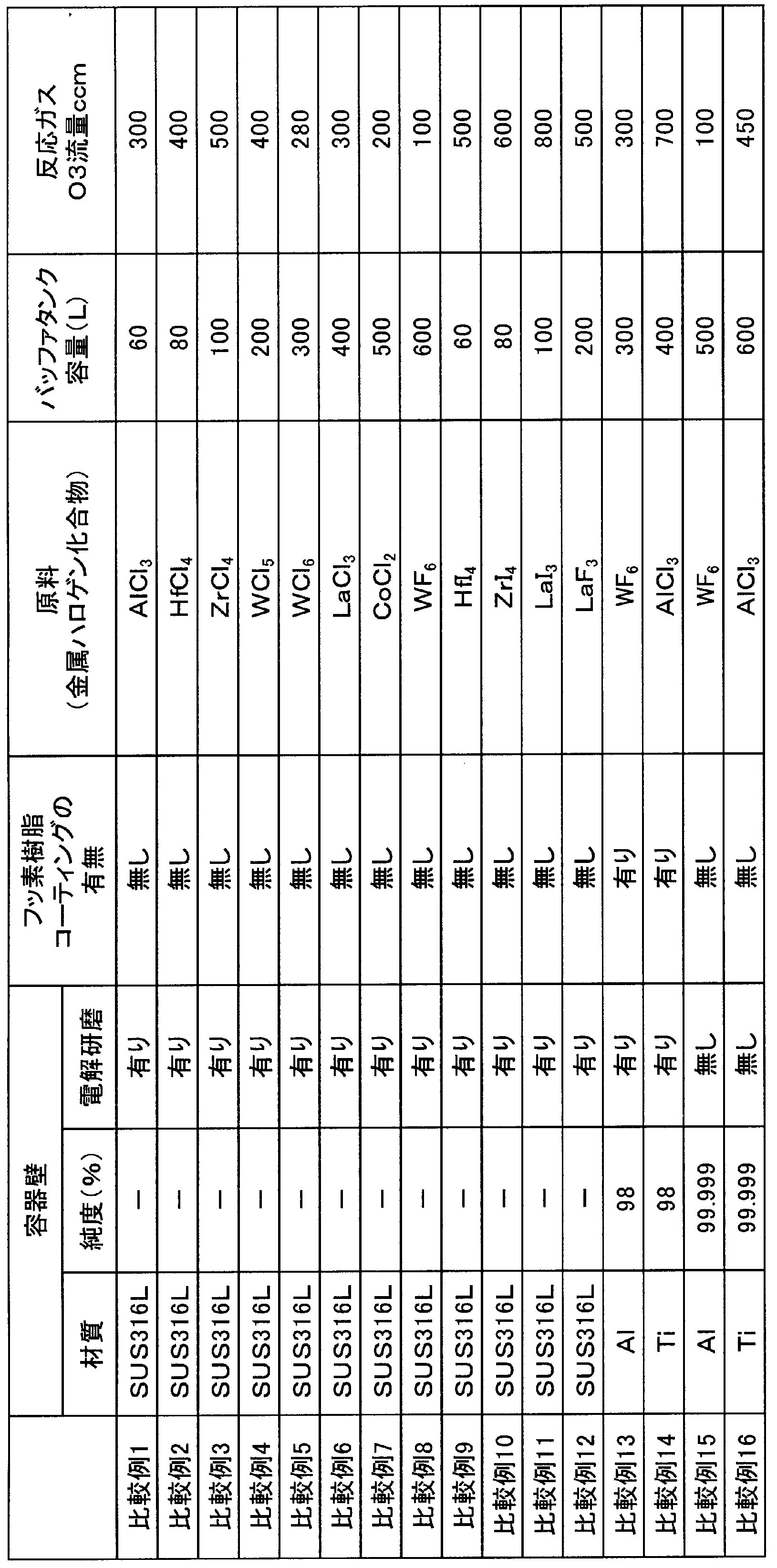
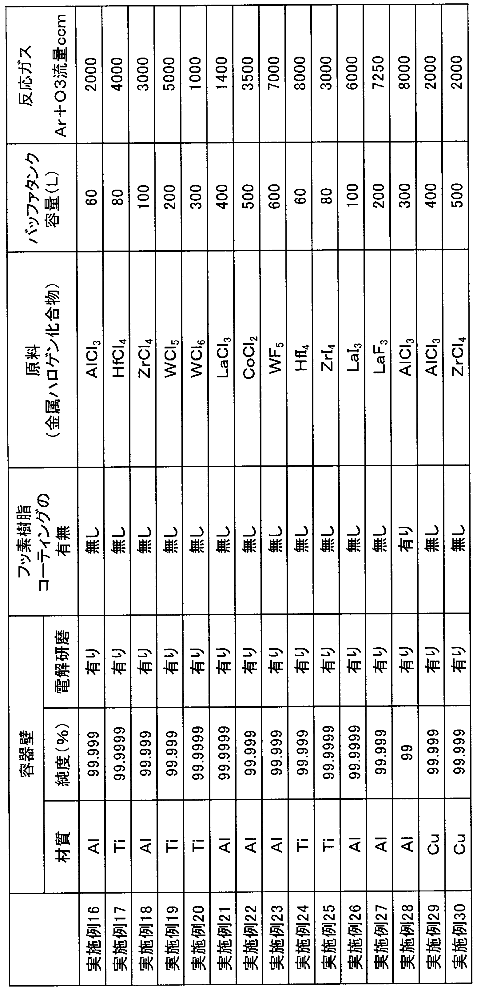
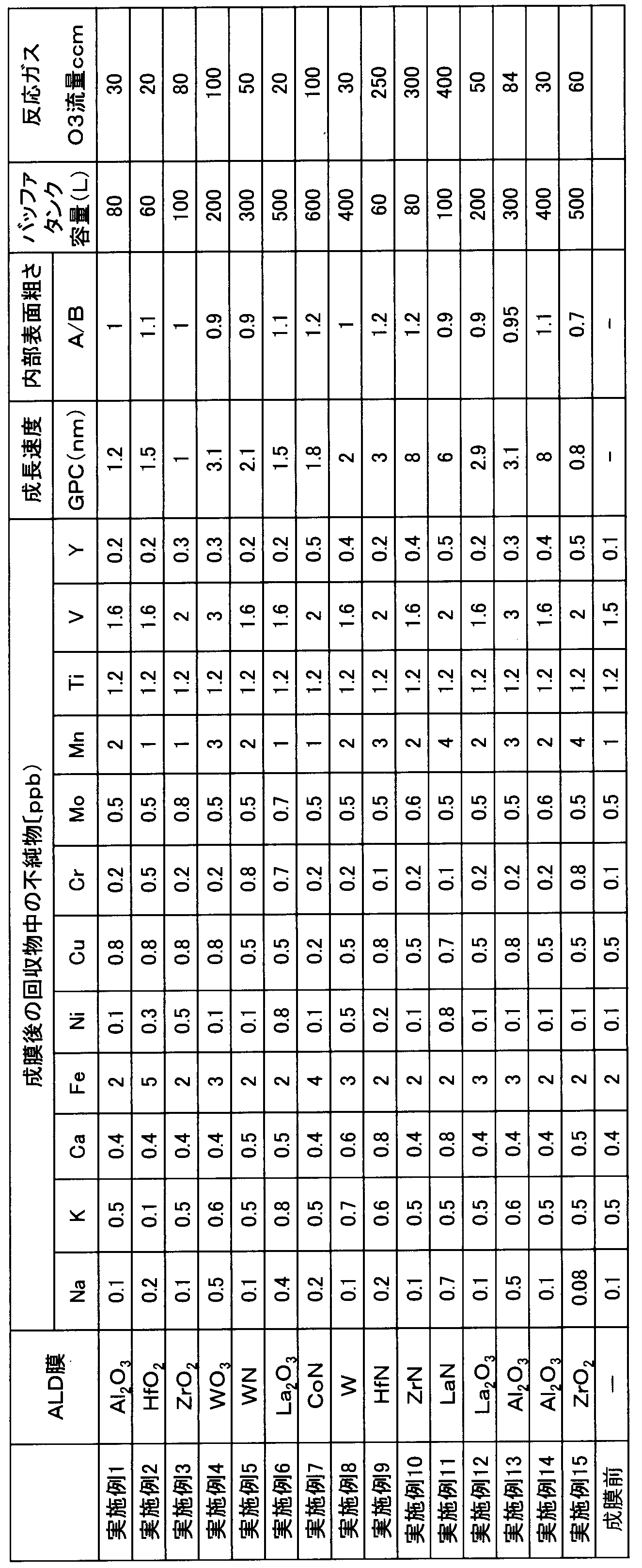

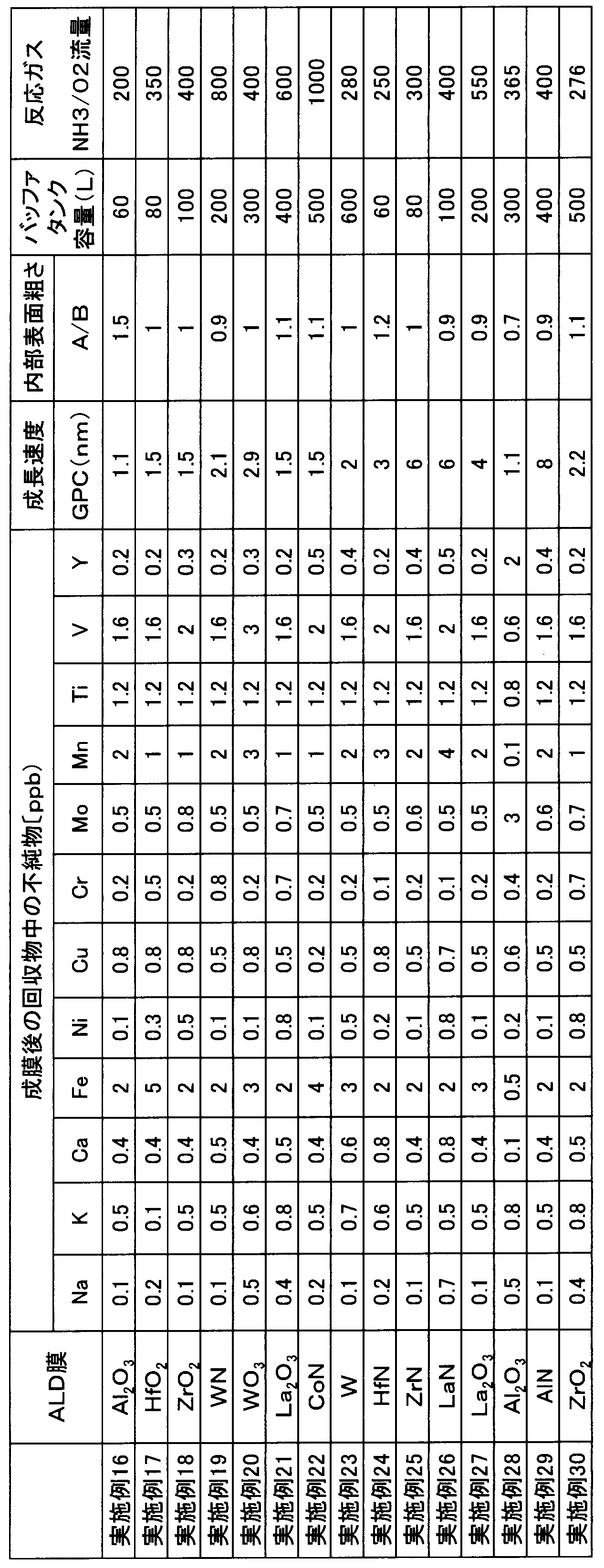
(実施例31~45)
実施例31~45においては、実施例1~15と同様の方法で蒸発原料用容器を作製した。なお、実施例31では、実施例1と同様の蒸発原料用容器を作製し、以下、実施例32以降も、順次、実施例2以降に対応する蒸発原料用容器を作製した。また、上述した方法でバッファタンクを作製し、蒸発原料用容器とバッファタンクとをガス配管によって接続して固体気化供給システムを作製した。蒸発原料用容器とバッファタンクとを接続するガス配管の一部には、CV値(水置換)が1.5のバルブを配置し、このようなバルブを経由して混合ガスの供給を行った。バッファタンクの容量については、表7に示す通りである。そして、実施例1~15と同様の方法で、原子層堆積(ALD)法による成膜を行った。実施例31~45においては、蒸発原料用容器内には、球状部材などの充填物を充填せずに、混合ガスの生成を行った。
実施例31~45においては、実施例1~15と同様の方法で蒸発原料用容器を作製した。なお、実施例31では、実施例1と同様の蒸発原料用容器を作製し、以下、実施例32以降も、順次、実施例2以降に対応する蒸発原料用容器を作製した。また、上述した方法でバッファタンクを作製し、蒸発原料用容器とバッファタンクとをガス配管によって接続して固体気化供給システムを作製した。蒸発原料用容器とバッファタンクとを接続するガス配管の一部には、CV値(水置換)が1.5のバルブを配置し、このようなバルブを経由して混合ガスの供給を行った。バッファタンクの容量については、表7に示す通りである。そして、実施例1~15と同様の方法で、原子層堆積(ALD)法による成膜を行った。実施例31~45においては、蒸発原料用容器内には、球状部材などの充填物を充填せずに、混合ガスの生成を行った。
(比較例17~32)
比較例17~32においては、比較例1~16と同様の方法で蒸発原料用容器を作製した。なお、比較例17では、比較例1と同様の蒸発原料用容器を作製し、以下、比較例18以降も、順次、比較例2以降に対応する蒸発原料用容器を作製した。比較例17~32においては、バッファタンクを用いずに、蒸発原料用容器及びに接続されたガス配管を固体気化供給システムとし、蒸発原料用容器から混合ガスを直接供給することにより、原子層堆積(ALD)法による成膜を行った。
比較例17~32においては、比較例1~16と同様の方法で蒸発原料用容器を作製した。なお、比較例17では、比較例1と同様の蒸発原料用容器を作製し、以下、比較例18以降も、順次、比較例2以降に対応する蒸発原料用容器を作製した。比較例17~32においては、バッファタンクを用いずに、蒸発原料用容器及びに接続されたガス配管を固体気化供給システムとし、蒸発原料用容器から混合ガスを直接供給することにより、原子層堆積(ALD)法による成膜を行った。
実施例31~45及び比較例17~32における原子層堆積(ALD)法によって成膜されたALD膜の組成を、表7及び表8に示す。また、成膜後の蒸発原料中の不純物(表7及び表8に示す12成種の元素)の量をICPMS(誘導結合プラズマ質量分析計)によって測定した。なお、表7の「成膜前」の欄において、成膜前の蒸発原料中の不純物(表7及び表8に示す12成種の元素)の量を記載している。また、各実施例及び比較例における反応ガスの流量を、表7及び表8に示す。また、上述した方法と同様の方法で、「内部表面粗さ」及び「成長速度」を測定した。結果を、表7及び表8に示す。
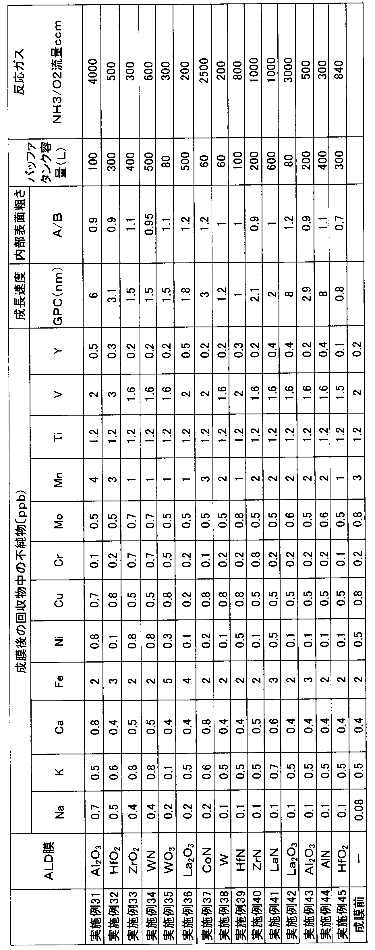
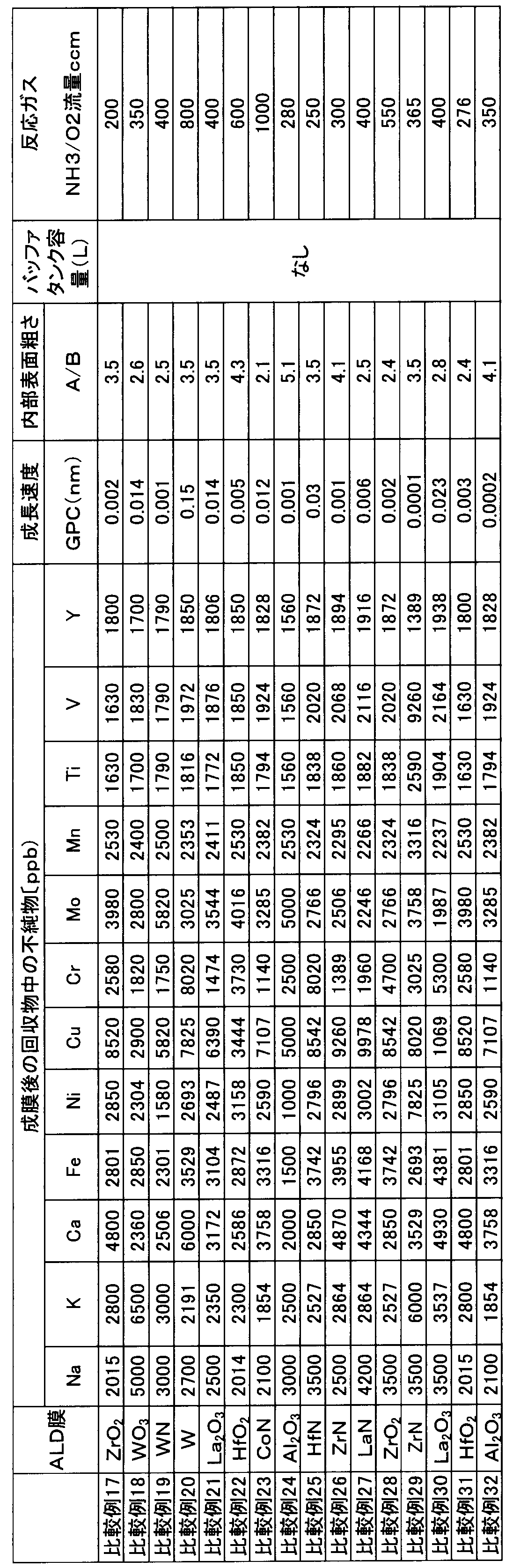
(結果)
表4~表8の結果から分かるように、実施例1~45の固体気化供給システムは、比較例1~32の固体気化供給システムに比べて、不純物の量が少ないことが分かる。また、実施例1~45の固体気化供給システムの蒸発原料用容器は、「内部表面粗さ」の「A/B」の値が1に近い値となり、成膜前後における表面粗さの差が小さいことが分かる。ここで、この表面粗さの差が小さいということは、蒸発原料による腐食の程度が少なかったことを表しており、耐腐食性が高いことが分かる。このような結果から、実施例1~45の固体気化供給システム(特に、蒸発原料用容器は)は、耐腐食性に優れたものであることが分かる。また、実施例1~45の固体気化供給システムは、蒸発原料用容器の下流側にバッファタンクを備えているため、蒸発原料を含む混合ガスを、高流量且つ安定的に供給することができ、ALD膜の成長において、優れた成長速度を実現することが可能であった。
表4~表8の結果から分かるように、実施例1~45の固体気化供給システムは、比較例1~32の固体気化供給システムに比べて、不純物の量が少ないことが分かる。また、実施例1~45の固体気化供給システムの蒸発原料用容器は、「内部表面粗さ」の「A/B」の値が1に近い値となり、成膜前後における表面粗さの差が小さいことが分かる。ここで、この表面粗さの差が小さいということは、蒸発原料による腐食の程度が少なかったことを表しており、耐腐食性が高いことが分かる。このような結果から、実施例1~45の固体気化供給システム(特に、蒸発原料用容器は)は、耐腐食性に優れたものであることが分かる。また、実施例1~45の固体気化供給システムは、蒸発原料用容器の下流側にバッファタンクを備えているため、蒸発原料を含む混合ガスを、高流量且つ安定的に供給することができ、ALD膜の成長において、優れた成長速度を実現することが可能であった。
本発明の薄膜形成用金属ハロゲン化合物の固体気化供給システムは、化学気相成長(CVD)法、有機金属化学気相成長(MOCVD)法、原子層堆積(ALD)法による成膜に利用することができる。
2:容器本体、4:蓋体、6:締結部材、8:継手部材、10:フッ素樹脂コーティング、12:容器壁、12a:内壁部材、12b:外壁部材、14:二重壁構造、16:キャリアガス導入口、18:混合ガス導出口、20:容器内導入口、22:棚部材、24:貫通孔、26:球状部材、30:バルブ、32:圧力計、34:ガス配管、500:固体気化供給システム、100,200,300:蒸発原料用容器、101:バッファタンク、102:原料供給源、103:半導体処理設備、104:熱交換器、105:温度コントローラ、106:供給制御手段、107:キャリアガス供給手段、A:薄膜形成用金属ハロゲン化合物(原料供給源から供給される薄膜形成用金属ハロゲン化合物)、G1:キャリアガス、G2:蒸発した薄膜形成用金属ハロゲン化合物(蒸発した蒸発原料)、G3:混合ガス、S:薄膜形成用金属ハロゲン化合物(蒸発原料)。
Claims (12)
- 蒸発原料としての薄膜形成用金属ハロゲン化合物を貯留し且つ蒸発させるための蒸発原料用容器と、前記蒸発原料用容器に接続されたバッファタンクと、を備えた薄膜形成用金属ハロゲン化合物の固体気化供給システムであって、
前記蒸発原料用容器は、
容器壁を有する容器本体と、
前記容器本体に着脱自在に構成され、前記容器本体内にキャリアガスを導入するキャリアガス導入口及び蒸発した前記薄膜形成用金属ハロゲン化合物と前記キャリアガスとの混合ガスを外部に導出する混合ガス導出口を有する蓋体と、
前記容器本体と前記蓋体とを固定する締結部材と、
前記蓋体の前記キャリアガス導入口及び前記混合ガス導出口に配設された継手部材と、を備え、
前記容器本体の前記容器壁は、内壁部材及び外壁部材によって構成された二重壁構造を有し、前記キャリアガス導入口から導入された前記キャリアガスが、前記二重壁構造の前記内壁部材と前記外壁部材の間を経由して前記容器本体内に導入されるように構成され、且つ、
前記容器本体の前記容器壁が、純度99~99.9999%の銅、純度99~99.9999%のアルミニウム、又は純度99~99.9999%のチタンから構成され、
前記容器本体、前記蓋体、前記締結部材、及び前記継手部材のそれぞれには、フッ素樹脂コーティングが施されている、及び/又は、それぞれの表面に電解研磨が施されている、固体気化供給システム。 - 前記蒸発原料用容器と前記バッファタンクとを接続するガス流路の一部に配設されたバルブを更に備え、
前記バルブは、CV値(水置換)が0.2以上の真空バルブである、請求項1に記載の固体気化供給システム。 - 前記容器壁を構成する前記内壁部材の底面部に、前記内壁部材と前記外壁部材の間を経由した前記キャリアガスが前記容器本体に導入される容器内導入口を有する、請求項1又は2に記載の固体気化供給システム。
- 前記締結部材が、前記容器本体及び前記蓋体に設けられたボルト挿入孔に挿入されたボルト部材及び前記ボルト部材に螺合して締結したナット部材からなる、請求項1又は2に記載の固体気化供給システム。
- 前記容器本体内に懸架された、少なくとも1つの板状の棚部材を更に有する、請求項1又は2に記載の固体気化供給システム。
- 前記棚部材の少なくとも1つは、複数の貫通孔が形成されたシャワーヘッド構造を有する、請求項5に記載の固体気化供給システム。
- 前記棚部材の少なくとも1つは、多孔質体によって構成されている、請求項5に記載の固体気化供給システム。
- 前記容器本体内に、一の方向における最大長さが1~30mmで、アルミニウム製又は銅製の、一以上の球状、長球状、葉状、螺旋状、又はその他不定形状の部材を更に有する、請求項1、2、6及び7のいずれか一項に記載の固体気化供給システム。
- 前記蒸発原料としての前記薄膜形成用金属ハロゲン化合物が、下記一般式(1)で表される化合物である、請求項1、2、6及び7のいずれか一項に記載の固体気化供給システム。
一般式(1):MXn
(但し、前記一般式(1)において、Mは、Al、Hf、Zr、Ta、W、Ga、La、Ce、Pr、Nd、Sm、Eu、Gd、Tb、Dy、Er、Tm、Yb及びCoのいずれかの元素を示す。Xは、ハロゲン元素を示す。nは、Xの数である。) - 化学気相成長法による成膜に用いられる、請求項1、2、6及び7のいずれか一項に記載の固体気化供給システム。
- 原子層堆積法による成膜に用いられる、請求項1、2、6及び7のいずれか一項に記載の固体気化供給システム。
- 前記蒸発原料用容器の前記容器本体内に前記キャリアガスを供給するキャリアガス供給手段を更に備える、請求項1、2、6及び7のいずれか一項に記載の固体気化供給システム。
Priority Applications (3)
| Application Number | Priority Date | Filing Date | Title |
|---|---|---|---|
| US17/424,968 US11613809B2 (en) | 2019-02-07 | 2020-02-05 | Solid vaporization/supply system of metal halide for thin film deposition |
| CN202080013066.8A CN113366142A (zh) | 2019-02-07 | 2020-02-05 | 薄膜形成用金属卤化物的固体气化供给系统 |
| KR1020217028595A KR102475511B1 (ko) | 2019-02-07 | 2020-02-05 | 박막 형성용 금속 할로겐 화합물의 고체 기화 공급 시스템 |
Applications Claiming Priority (2)
| Application Number | Priority Date | Filing Date | Title |
|---|---|---|---|
| JP2019020584A JP6901153B2 (ja) | 2019-02-07 | 2019-02-07 | 薄膜形成用金属ハロゲン化合物の固体気化供給システム。 |
| JP2019-020584 | 2019-02-07 |
Publications (1)
| Publication Number | Publication Date |
|---|---|
| WO2020162500A1 true WO2020162500A1 (ja) | 2020-08-13 |
Family
ID=71948041
Family Applications (1)
| Application Number | Title | Priority Date | Filing Date |
|---|---|---|---|
| PCT/JP2020/004368 Ceased WO2020162500A1 (ja) | 2019-02-07 | 2020-02-05 | 薄膜形成用金属ハロゲン化合物の固体気化供給システム |
Country Status (6)
| Country | Link |
|---|---|
| US (1) | US11613809B2 (ja) |
| JP (1) | JP6901153B2 (ja) |
| KR (1) | KR102475511B1 (ja) |
| CN (1) | CN113366142A (ja) |
| TW (1) | TWI741495B (ja) |
| WO (1) | WO2020162500A1 (ja) |
Cited By (3)
| Publication number | Priority date | Publication date | Assignee | Title |
|---|---|---|---|---|
| CN114277357A (zh) * | 2020-09-28 | 2022-04-05 | 株式会社国际电气 | 气化系统、基板处理装置以及半导体装置的制造方法 |
| US11566326B2 (en) * | 2019-02-07 | 2023-01-31 | Kojundo Chemical Laboratory Co., Ltd. | Vaporizable source material container and solid vaporization/supply system using the same |
| US11613809B2 (en) | 2019-02-07 | 2023-03-28 | Kojundo Chemical Laboratory Co., Ltd. | Solid vaporization/supply system of metal halide for thin film deposition |
Families Citing this family (9)
| Publication number | Priority date | Publication date | Assignee | Title |
|---|---|---|---|---|
| CN114391051B (zh) * | 2019-09-18 | 2024-06-04 | 东京毅力科创株式会社 | 原料气体供给系统和原料气体供给方法 |
| US12540390B2 (en) * | 2020-03-17 | 2026-02-03 | Tokyo Electron Limited | Raw material supply system |
| US11834740B2 (en) * | 2020-11-10 | 2023-12-05 | Applied Materials, Inc. | Apparatus, system, and method for generating gas for use in a process chamber |
| KR102310908B1 (ko) * | 2021-04-30 | 2021-10-08 | (주) 리노닉스 | 질소 가스의 단독 사용이 가능한 캐리어 가스 공급장치 |
| US11584990B2 (en) * | 2021-07-02 | 2023-02-21 | Applied Materials, Inc. | Bottom fed sublimation bed for high saturation efficiency in semiconductor applications |
| US20240318310A1 (en) * | 2021-07-06 | 2024-09-26 | Kojundo Chemical Laboratory Co., Ltd. | Container for volatile raw materials, and solid gasification and supply system |
| JP7675366B2 (ja) * | 2021-07-09 | 2025-05-13 | 日本エア・リキード合同会社 | 昇華ガス供給システムおよび昇華ガス供給方法 |
| CN115000252B (zh) * | 2022-06-16 | 2025-08-22 | 苏州科技大学 | 稀土掺杂GaN纳米薄膜的制备方法 |
| KR102764569B1 (ko) | 2022-12-16 | 2025-02-06 | 정로기업(주) | 철골 구조물 시공 방법 |
Citations (8)
| Publication number | Priority date | Publication date | Assignee | Title |
|---|---|---|---|---|
| JPH0125850B2 (ja) * | 1985-12-21 | 1989-05-19 | Kinukon Kk | |
| JP2009084625A (ja) * | 2007-09-28 | 2009-04-23 | Tokyo Electron Ltd | 原料ガスの供給システム及び成膜装置 |
| JP2010502833A (ja) * | 2006-08-31 | 2010-01-28 | アドバンスド テクノロジー マテリアルズ,インコーポレイテッド | 制御された固体モルフォロジを利用する、固体前駆体に基づいた流体の送出 |
| WO2014069174A1 (ja) * | 2012-10-29 | 2014-05-08 | 富士電機株式会社 | 半導体装置 |
| JP2016134569A (ja) * | 2015-01-21 | 2016-07-25 | 株式会社東芝 | 半導体製造装置 |
| JP2016208026A (ja) * | 2015-04-18 | 2016-12-08 | エア プロダクツ アンド ケミカルズ インコーポレイテッドAir Products And Chemicals Incorporated | 前駆体材料の送達のための容器及び方法 |
| JP2017191826A (ja) * | 2016-04-12 | 2017-10-19 | 三菱電機株式会社 | 半導体装置およびその製造方法 |
| JP2018506859A (ja) * | 2015-02-13 | 2018-03-08 | インテグリス・インコーポレーテッド | 基材物品および装置の特性および性能を増強するためのコーティング |
Family Cites Families (67)
| Publication number | Priority date | Publication date | Assignee | Title |
|---|---|---|---|---|
| US529684A (en) | 1894-11-20 | Treating air for medical purposes | ||
| US1803306A (en) * | 1927-01-08 | 1931-04-28 | Commercial Solvents Corp | Catalytic apparatus |
| US3438803A (en) | 1965-05-18 | 1969-04-15 | Anchor Hocking Glass Corp | Method and means for vapor coating |
| US3459668A (en) | 1965-05-21 | 1969-08-05 | Honeywell Inc | Semiconductor method and apparatus |
| US3832222A (en) | 1972-12-27 | 1974-08-27 | Atomic Energy Commission | Chemical vapor deposition of uranium and plutonium |
| JPS6021382A (ja) * | 1983-07-15 | 1985-02-02 | Canon Inc | プラズマcvd装置 |
| JP2976333B2 (ja) | 1987-10-24 | 1999-11-10 | 忠弘 大見 | ステンレス鋼及びその製造方法並びに減圧装置 |
| DE3801147A1 (de) | 1988-01-16 | 1989-07-27 | Philips Patentverwaltung | Vorrichtung zum erzeugen eines mit dem dampf eines wenig fluechtigen stoffes angereicherten gasstroms |
| CA2031765C (en) | 1989-12-08 | 1996-02-20 | Masahide Nomura | Method and system for performing control conforming with characteristics of controlled system |
| US5314780A (en) * | 1991-02-28 | 1994-05-24 | Canon Kabushiki Kaisha | Method for treating metal substrate for electro-photographic photosensitive member and method for manufacturing electrophotographic photosensitive member |
| JPH05267196A (ja) | 1992-01-24 | 1993-10-15 | Japan Energy Corp | 強誘電体薄膜の作製方法 |
| WO1994014530A1 (fr) | 1992-12-28 | 1994-07-07 | Kao Corporation | Procede et appareil permettant de produire de fines particules de ceramique |
| US5630878A (en) * | 1994-02-20 | 1997-05-20 | Stec Inc. | Liquid material-vaporizing and supplying apparatus |
| US5558687A (en) | 1994-12-30 | 1996-09-24 | Corning Incorporated | Vertical, packed-bed, film evaporator for halide-free, silicon-containing compounds |
| US6599399B2 (en) * | 1997-03-07 | 2003-07-29 | Applied Materials, Inc. | Sputtering method to generate ionized metal plasma using electron beams and magnetic field |
| JPH11111644A (ja) * | 1997-09-30 | 1999-04-23 | Japan Pionics Co Ltd | 気化供給装置 |
| US6135433A (en) * | 1998-02-27 | 2000-10-24 | Air Liquide America Corporation | Continuous gas saturation system and method |
| JP3909792B2 (ja) | 1999-08-20 | 2007-04-25 | パイオニア株式会社 | 化学気相成長法における原料供給装置及び原料供給方法 |
| US6884295B2 (en) | 2000-05-29 | 2005-04-26 | Tokyo Electron Limited | Method of forming oxynitride film or the like and system for carrying out the same |
| US6455414B1 (en) * | 2000-11-28 | 2002-09-24 | Tokyo Electron Limited | Method for improving the adhesion of sputtered copper films to CVD transition metal based underlayers |
| JP3680029B2 (ja) * | 2001-08-08 | 2005-08-10 | 三菱重工業株式会社 | 金属薄膜の気相成長方法およびその気相成長装置 |
| US7090727B2 (en) | 2001-08-17 | 2006-08-15 | Micron Technology, Inc. | Heated gas line body feedthrough for vapor and gas delivery systems and methods for employing same |
| AU2003248822A1 (en) | 2002-07-03 | 2004-01-23 | Stone And Webster Process Technology, Inc. | Condensation reduction in fluid maxing |
| US7300038B2 (en) | 2002-07-23 | 2007-11-27 | Advanced Technology Materials, Inc. | Method and apparatus to help promote contact of gas with vaporized material |
| US6915592B2 (en) * | 2002-07-29 | 2005-07-12 | Applied Materials, Inc. | Method and apparatus for generating gas to a processing chamber |
| KR101183109B1 (ko) * | 2002-07-30 | 2012-09-24 | 에이에스엠 아메리카, 인코포레이티드 | 캐리어 가스를 이용하는 승화 시스템 |
| US7192486B2 (en) * | 2002-08-15 | 2007-03-20 | Applied Materials, Inc. | Clog-resistant gas delivery system |
| JP2004335564A (ja) | 2003-05-01 | 2004-11-25 | Japan Pionics Co Ltd | 気化器 |
| US9725805B2 (en) | 2003-06-27 | 2017-08-08 | Spts Technologies Limited | Apparatus and method for controlled application of reactive vapors to produce thin films and coatings |
| JP2005131632A (ja) | 2003-10-08 | 2005-05-26 | Adeka Engineering & Consutruction Co Ltd | 流体供給装置 |
| US7484315B2 (en) * | 2004-11-29 | 2009-02-03 | Tokyo Electron Limited | Replaceable precursor tray for use in a multi-tray solid precursor delivery system |
| US20060185597A1 (en) * | 2004-11-29 | 2006-08-24 | Kenji Suzuki | Film precursor evaporation system and method of using |
| US7708835B2 (en) | 2004-11-29 | 2010-05-04 | Tokyo Electron Limited | Film precursor tray for use in a film precursor evaporation system and method of using |
| US7488512B2 (en) | 2004-11-29 | 2009-02-10 | Tokyo Electron Limited | Method for preparing solid precursor tray for use in solid precursor evaporation system |
| US7638002B2 (en) | 2004-11-29 | 2009-12-29 | Tokyo Electron Limited | Multi-tray film precursor evaporation system and thin film deposition system incorporating same |
| US7722720B2 (en) * | 2004-12-08 | 2010-05-25 | Rohm And Haas Electronic Materials Llc | Delivery device |
| US20080191153A1 (en) | 2005-03-16 | 2008-08-14 | Advanced Technology Materials, Inc. | System For Delivery Of Reagents From Solid Sources Thereof |
| US7651570B2 (en) | 2005-03-31 | 2010-01-26 | Tokyo Electron Limited | Solid precursor vaporization system for use in chemical vapor deposition |
| KR20070031723A (ko) * | 2005-09-15 | 2007-03-20 | 삼성전자주식회사 | 약액 공급 장치 |
| US7833355B2 (en) * | 2006-06-02 | 2010-11-16 | Peter David Capizzo | Carbon nanotube (CNT) extrusion methods and CNT wire and composites |
| US7846256B2 (en) | 2007-02-23 | 2010-12-07 | Tokyo Electron Limited | Ampule tray for and method of precursor surface area |
| JP4900110B2 (ja) | 2007-07-20 | 2012-03-21 | 東京エレクトロン株式会社 | 薬液気化タンク及び薬液処理システム |
| CA2717943C (en) | 2008-03-11 | 2014-01-28 | Fukuoka University | Phosphine compound, process for producing the same, and peroxide scavenger using the same |
| JP5696348B2 (ja) | 2008-08-09 | 2015-04-08 | 東京エレクトロン株式会社 | 金属回収方法、金属回収装置、排気系及びこれを用いた成膜装置 |
| US20100119734A1 (en) * | 2008-11-07 | 2010-05-13 | Applied Materials, Inc. | Laminar flow in a precursor source canister |
| EP2496733B1 (en) | 2009-11-02 | 2021-08-04 | Sigma-Aldrich Co. LLC | Method for evaporation |
| WO2012046672A1 (ja) * | 2010-10-04 | 2012-04-12 | 東京エレクトロン株式会社 | 成膜装置及び成膜材料供給方法 |
| US10385452B2 (en) | 2012-05-31 | 2019-08-20 | Entegris, Inc. | Source reagent-based delivery of fluid with high material flux for batch deposition |
| US10526707B2 (en) * | 2012-08-29 | 2020-01-07 | The University Of Tokyo | Heat exchanger type reaction tube |
| US9523151B2 (en) | 2014-02-21 | 2016-12-20 | Tokyo Electron Limited | Vaporizer unit with open cell core and method of operating |
| KR101899201B1 (ko) | 2015-03-27 | 2018-09-14 | 도쿄엘렉트론가부시키가이샤 | 원료 공급 장치, 원료 공급 방법 및 기억 매체 |
| WO2017009997A1 (ja) | 2015-07-16 | 2017-01-19 | 株式会社日立国際電気 | 基板処理装置、半導体装置の製造方法及び気化システム |
| US20160046408A1 (en) * | 2015-10-27 | 2016-02-18 | L'Air Liquide, Société Anonyme pour l'Etude et l'Exploitation des Procédés Georges Claude | Internally coated vessel for housing a metal halide |
| WO2017104485A1 (ja) | 2015-12-18 | 2017-06-22 | 株式会社日立国際電気 | 貯留装置、気化器、基板処理装置および半導体装置の製造方法 |
| US11136169B2 (en) * | 2016-04-19 | 2021-10-05 | Entegris, Inc. | Tamper-resistant chemical reagent package |
| US10483498B2 (en) | 2016-04-22 | 2019-11-19 | Universal Display Corporation | High efficiency vapor transport sublimation source using baffles coated with source material |
| JP6880725B2 (ja) * | 2016-12-27 | 2021-06-02 | 日亜化学工業株式会社 | 発光装置 |
| WO2019023011A1 (en) * | 2017-07-25 | 2019-01-31 | Linde Aktiengesellschaft | SUBLIMATOR APPARATUS FOR SOLID COMPOSITIONS, SYSTEMS AND METHODS OF USING THE SAME |
| KR102344996B1 (ko) | 2017-08-18 | 2021-12-30 | 삼성전자주식회사 | 전구체 공급 유닛, 기판 처리 장치 및 그를 이용한 반도체 소자의 제조방법 |
| JP6425850B1 (ja) * | 2017-11-22 | 2018-11-21 | 日本エア・リキード株式会社 | 固体材料容器およびその固体材料容器に固体材料が充填されている固体材料製品 |
| JP6462096B1 (ja) * | 2017-11-22 | 2019-01-30 | 日本エア・リキード株式会社 | 固体材料容器およびその固体材料容器に固体材料が充填されている固体材料製品 |
| JP7076999B2 (ja) * | 2017-12-14 | 2022-05-30 | 日本エア・リキード合同会社 | 固体材料の前処理方法および固体材料が充填されている固体材料製品を製造する方法 |
| US11166441B2 (en) | 2018-07-13 | 2021-11-09 | Versum Materials Us, Llc | Vapor delivery container with flow distributor |
| JP6887688B2 (ja) * | 2019-02-07 | 2021-06-16 | 株式会社高純度化学研究所 | 蒸発原料用容器、及びその蒸発原料用容器を用いた固体気化供給システム |
| JP6901153B2 (ja) * | 2019-02-07 | 2021-07-14 | 株式会社高純度化学研究所 | 薄膜形成用金属ハロゲン化合物の固体気化供給システム。 |
| WO2020219702A1 (en) * | 2019-04-26 | 2020-10-29 | Entegris, Inc. | Vaporization vessel and method |
| US11821078B2 (en) * | 2020-04-15 | 2023-11-21 | Asm Ip Holding B.V. | Method for forming precoat film and method for forming silicon-containing film |
-
2019
- 2019-02-07 JP JP2019020584A patent/JP6901153B2/ja active Active
-
2020
- 2020-02-05 KR KR1020217028595A patent/KR102475511B1/ko active Active
- 2020-02-05 US US17/424,968 patent/US11613809B2/en active Active
- 2020-02-05 CN CN202080013066.8A patent/CN113366142A/zh active Pending
- 2020-02-05 WO PCT/JP2020/004368 patent/WO2020162500A1/ja not_active Ceased
- 2020-02-07 TW TW109103782A patent/TWI741495B/zh active
Patent Citations (8)
| Publication number | Priority date | Publication date | Assignee | Title |
|---|---|---|---|---|
| JPH0125850B2 (ja) * | 1985-12-21 | 1989-05-19 | Kinukon Kk | |
| JP2010502833A (ja) * | 2006-08-31 | 2010-01-28 | アドバンスド テクノロジー マテリアルズ,インコーポレイテッド | 制御された固体モルフォロジを利用する、固体前駆体に基づいた流体の送出 |
| JP2009084625A (ja) * | 2007-09-28 | 2009-04-23 | Tokyo Electron Ltd | 原料ガスの供給システム及び成膜装置 |
| WO2014069174A1 (ja) * | 2012-10-29 | 2014-05-08 | 富士電機株式会社 | 半導体装置 |
| JP2016134569A (ja) * | 2015-01-21 | 2016-07-25 | 株式会社東芝 | 半導体製造装置 |
| JP2018506859A (ja) * | 2015-02-13 | 2018-03-08 | インテグリス・インコーポレーテッド | 基材物品および装置の特性および性能を増強するためのコーティング |
| JP2016208026A (ja) * | 2015-04-18 | 2016-12-08 | エア プロダクツ アンド ケミカルズ インコーポレイテッドAir Products And Chemicals Incorporated | 前駆体材料の送達のための容器及び方法 |
| JP2017191826A (ja) * | 2016-04-12 | 2017-10-19 | 三菱電機株式会社 | 半導体装置およびその製造方法 |
Cited By (4)
| Publication number | Priority date | Publication date | Assignee | Title |
|---|---|---|---|---|
| US11566326B2 (en) * | 2019-02-07 | 2023-01-31 | Kojundo Chemical Laboratory Co., Ltd. | Vaporizable source material container and solid vaporization/supply system using the same |
| US11613809B2 (en) | 2019-02-07 | 2023-03-28 | Kojundo Chemical Laboratory Co., Ltd. | Solid vaporization/supply system of metal halide for thin film deposition |
| CN114277357A (zh) * | 2020-09-28 | 2022-04-05 | 株式会社国际电气 | 气化系统、基板处理装置以及半导体装置的制造方法 |
| TWI810659B (zh) * | 2020-09-28 | 2023-08-01 | 日商國際電氣股份有限公司 | 氣化系統,基板處理裝置及半導體裝置的製造方法 |
Also Published As
| Publication number | Publication date |
|---|---|
| US20220064786A1 (en) | 2022-03-03 |
| TWI741495B (zh) | 2021-10-01 |
| JP2020128566A (ja) | 2020-08-27 |
| KR102475511B1 (ko) | 2022-12-07 |
| CN113366142A (zh) | 2021-09-07 |
| TW202100792A (zh) | 2021-01-01 |
| US11613809B2 (en) | 2023-03-28 |
| JP6901153B2 (ja) | 2021-07-14 |
| KR20210118195A (ko) | 2021-09-29 |
Similar Documents
| Publication | Publication Date | Title |
|---|---|---|
| JP6901153B2 (ja) | 薄膜形成用金属ハロゲン化合物の固体気化供給システム。 | |
| JP6887688B2 (ja) | 蒸発原料用容器、及びその蒸発原料用容器を用いた固体気化供給システム | |
| TWI846960B (zh) | 低揮發性前驅物的供應系統 | |
| JP5883104B2 (ja) | 容器から気相の前駆体を含む前駆体含有流体流を送出する方法 | |
| TWI903938B (zh) | 用於增強基材製品及設備之性質與表現的塗層 | |
| CN102695823B (zh) | 氮化物结晶的制造方法、制造容器和构件 | |
| TWI819647B (zh) | 蒸發原料用容器以及固體氣化供給系統 | |
| US20050257735A1 (en) | Method and apparatus for providing gas to a processing chamber | |
| JP2008060536A (ja) | 高流量のGaCl3供給 | |
| TW201920755A (zh) | 五氯化鎢調節和結晶相操縱 | |
| TW201945289A (zh) | 五氯化鎢調節和結晶相操縱 | |
| TW202428927A (zh) | 氣相前驅物遞送系統以及包括其的氣相沉積設備 | |
| JP7811020B2 (ja) | 蒸発原料用容器および固体気化供給システム | |
| WO2024127901A1 (ja) | 液化ガス入り容器および液化ガス入り容器の製造方法 | |
| JP2020002384A (ja) | 蒸発原料用容器及びその製造方法 |
Legal Events
| Date | Code | Title | Description |
|---|---|---|---|
| 121 | Ep: the epo has been informed by wipo that ep was designated in this application |
Ref document number: 20752302 Country of ref document: EP Kind code of ref document: A1 |
|
| NENP | Non-entry into the national phase |
Ref country code: DE |
|
| ENP | Entry into the national phase |
Ref document number: 20217028595 Country of ref document: KR Kind code of ref document: A |
|
| 122 | Ep: pct application non-entry in european phase |
Ref document number: 20752302 Country of ref document: EP Kind code of ref document: A1 |