WO2020196830A1 - Dispositif d'électrostimulation - Google Patents
Dispositif d'électrostimulation Download PDFInfo
- Publication number
- WO2020196830A1 WO2020196830A1 PCT/JP2020/014003 JP2020014003W WO2020196830A1 WO 2020196830 A1 WO2020196830 A1 WO 2020196830A1 JP 2020014003 W JP2020014003 W JP 2020014003W WO 2020196830 A1 WO2020196830 A1 WO 2020196830A1
- Authority
- WO
- WIPO (PCT)
- Prior art keywords
- electrodes
- main body
- user
- fixtures
- control unit
- Prior art date
- Legal status (The legal status is an assumption and is not a legal conclusion. Google has not performed a legal analysis and makes no representation as to the accuracy of the status listed.)
- Ceased
Links
Images


Classifications
-
- A—HUMAN NECESSITIES
- A61—MEDICAL OR VETERINARY SCIENCE; HYGIENE
- A61N—ELECTROTHERAPY; MAGNETOTHERAPY; RADIATION THERAPY; ULTRASOUND THERAPY
- A61N1/00—Electrotherapy; Circuits therefor
- A61N1/18—Applying electric currents by contact electrodes
- A61N1/32—Applying electric currents by contact electrodes alternating or intermittent currents
- A61N1/36—Applying electric currents by contact electrodes alternating or intermittent currents for stimulation
Definitions
- the present invention relates to an electrical stimulator.
- Patent Document 1 describes an electrical stimulator in which a pair of foot electrodes corresponding to the left and right feet are provided in the main body.
- the present inventor examined the electrical stimulator of Patent Document 1. As a result, it was recognized that there is room for improvement in improving the sensation of the electrical stimulation when the electrical stimulation is applied using the main body provided with the pair of foot electrodes.
- a certain aspect of the present invention is made in view of such a problem, and one of the purposes thereof is to provide an electric stimulator capable of improving the sensation by electric stimulation.
- an electrical stimulation device that applies electrical stimulation to a user's muscles, and the main body and the left and right feet of the user are individually attached to the main body.
- a pair of first electrodes provided and applied to the corresponding feet, a fitting attached to the lower body of the user, a second electrode provided on the fitting, and the pair of first electrodes and the second electrode.
- It includes a control unit that controls electrical stimulation power supplied from a power source.
- the sensation can be improved by the electric stimulus.
- FIG. 4A is a schematic diagram showing a first usage scene of the electrical stimulator of the first embodiment
- FIG. 4B is a schematic diagram showing the second usage scene.
- It is a block diagram which shows the function of the electric stimulator of 1st Embodiment.
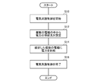
- It is a flowchart which shows an example of the operation of the electric stimulator of 1st Embodiment.
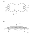
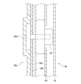
- 7 (A) is a back view of the second electrode of the first embodiment
- FIG. 7 (B) is a sectional view taken along the line AA of FIG.
- the electrical stimulator 10 is for applying electrical stimulation to the user's muscles.
- the term "user” refers to, for example, one having an average physique in the country in which the electrical stimulator 10 is sold.
- the electrical stimulator 10 can be used, for example, for strength training.
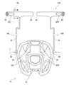
- the electrical stimulator 10 of the present embodiment includes a main body 12, attachments 14L and 14R, and connecting members 16L and 16R.
- the main body 12 of the present embodiment is used by being placed on the floor surface FL.
- the description will be made based on the case where the main body 12 is arranged on the horizontal floor surface FL.
- the description will be made using three directions orthogonal to each other.
- This direction is the front-rear direction X, the left-right direction Y, and the up-down direction Z.
- the front-back direction Y and the left-right direction Y are horizontal directions
- the up-down direction Z is a vertical direction.
- the main body 12 is provided with a pair of footrests 18L and 18R that individually correspond to the left and right foot Fts of the user.
- the pair of foot rests 18L and 18R includes a left foot rest 18L corresponding to the left foot and a right foot rest 18R corresponding to the right foot.
- the footrests 18L and 18R have a shape on which at least a part of the corresponding foot Ft can be placed.
- the footrest portions 18L and 18R of the present embodiment are composed of a plurality of footrest regions 20A and 20B.
- the plurality of foot rest areas 20A and 20B include a heel side foot rest area 20A on which at least the heel of the foot Ft can be placed, and a toe side foot rest area 20B on which at least the toes of the foot Ft can be placed.
- the main body 12 is provided with a pair of first electrodes 22L and 22R.
- the pair of first electrodes 22L and 22R are individually provided corresponding to the left and right feet, respectively.
- the pair of first electrodes 22L and 22R of the present embodiment includes a left first electrode 22L corresponding to the left foot and a right first electrode 22R corresponding to the right foot. It can be considered that the pair of first electrodes 22L and 22R correspond to each of the left and right halves of the user.
- the pair of first electrodes 22L and 22R is for applying an electronic stimulus to the corresponding user's foot (half body).
- Each of the pair of first electrodes 22L and 22R of the present embodiment constitutes each of the pair of footrest portions 18L and 18R.
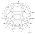
- the main body 12 of the present embodiment has a hollow structure, and includes a housing 24 and a pad member 26 fixed to the housing 24 using screws or the like.
- the pad member 26 of the present embodiment constitutes the footrest portions 18L and 18R and the first electrodes 22L and 22R.
- the pad member 26 is constructed using, for example, conductive rubber.
- This conductive rubber is composed of, for example, a rubber base material such as ethylene propylene diene rubber mixed with a conductivity-imparting agent such as carbon black or metal powder.
- the main body 12 is provided with a plurality of operation units 28A and 28B used for changing the operation of the electrical stimulator 10.
- the plurality of operation units 28A and 28B of the present embodiment include a first operation unit 28A and a second operation unit 28B provided on the upper surface portion of the main body 12.
- the operation units 28A and 28B of the present embodiment are separate members from the housing 24, and are fixed to the housing 24 using screws or the like (not shown).
- the operation units 28A and 28B of the present embodiment constitute buttons that receive a push operation by the user.
- the fixtures 14L and 14R are attached to the user's body.
- the fixtures 14L and 14R of this embodiment are attached to the lower body of the user.
- the "lower body” includes the legs and hips
- the "legs” includes the legs and thighs.
- the attachments 14L and 14R of the present embodiment include a left side attachment 14L corresponding to the left half of the user and a right side attachment 14R corresponding to the right side of the user.
- the left side attachment 14L is attached to the upper thigh of the left leg
- the right side attachment 14R is attached to the upper thigh of the right leg.
- the fixtures 14L and 14R of this embodiment are planar structures having flexibility. Hereinafter, unless otherwise specified, the description will be made based on the state in which the fixtures 14L and 14R are developed in a plane.
- the fixtures 14L and 14R of the present embodiment form a long belt shape when viewed from the thickness direction (direction orthogonal to the paper surface in FIG. 1).
- the attachments 14L and 14R of the present embodiment are attached to the body by wrapping around the body.
- connection structures 30 that are detachably connected to each other are provided at both ends of the fixtures 14L and 14R in the longitudinal direction.
- the connection structure 30 of the present embodiment is a hook-and-loop fastener, but is not particularly limited and may be a snap button or the like.
- the fixtures 14L and 14R of the present embodiment have a hollow structure, and are integrated by sewing the outer edge portion of the front side fabric member 52 and the back side fabric member 54 (see FIG. 8).
- Second electrodes 32L and 32R are provided on the fixtures 14L and 14R.
- the fixtures 14L and 14R are provided with individual second electrodes 32L and 32R corresponding to the plurality of first electrodes 22L and 22R, respectively.
- the plurality of second electrodes 32L and 32R include a left second electrode 32L corresponding to the left first electrode 22L and a right second electrode 32R corresponding to the right first electrode 22R.
- the left side second electrode 32L of the present embodiment is provided on the left side attachment 14L
- the right side second electrode 32R is provided on the right side attachment 14R.
- the plurality of second electrodes 32L and 32R are provided corresponding to the left and right halves, respectively.
- the second electrodes 32L and 32R are for applying electrical stimulation to the half body of the corresponding user.
- the second electrodes 32L and 32R of the present embodiment are applied to the body at the same positions as the attachment positions of the attachments 14L and 14R to the body.
- the left second electrode 32L is applied to the upper thigh of the left leg
- the right second electrode 32R is applied to the upper thigh of the right leg.
- the connecting members 16L and 16R connect the main body 12 and the fixtures 14L and 14R.
- the connecting members 16L and 16R are individually provided corresponding to the plurality of attachments 14L and 14R, respectively, and connect the corresponding attachments 14L and 14R to the main body 12.
- the connection members 16L and 16R correspond to the left side attachment 14L and connect the left side attachment 14L and the main body 12, and the right side attachment 14R and the right side attachment 14R and the main body 12.
- the right side connecting member 16R is included.
- the main body 12 and the attachments 14L and 14R can be integrated by the connecting members 16L and 16R, which makes it easy to carry and use.
- the connecting members 16L and 16R of this embodiment include an electric cable 34. At least a part of the connecting members 16L and 16R has flexibility so as to be able to follow changes in the positions of the main body 12 and the attachments 14L and 14R.
- the "at least a part" here is the electric cable 34 in this embodiment.
- connection members 16L and 16R of the present embodiment can transmit electrical stimulation power from the control unit 48 (described later) mounted on the main body 12 to the second electrodes 32L and 32R of the fixtures 14L and 14R.
- the connecting members 16L and 16R are considered to be capable of transmitting electrical stimulation power supplied from the control unit 48 mounted on one of the main body 12 and the fixtures 14L and 14R to the electrodes provided on the other.
- the "one side” is the main body 12 in the present embodiment
- the “other side” is the fixtures 14 and 14R.
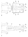
- the connecting members 16L and 16R are detachably connected to at least one of the main body 12 and the attachments 14L and 14R via the first connector 36.
- the connecting members 16L and 16R of the present embodiment are detachably connected to the main body 12, and are connected to the fixtures 14L and 14R by sewing, winding, gluing and the like.
- the first connector 36 is provided at the end of the electric cable 34 of the connecting members 16L and 16R, and the main body 12 is provided with a first receiving portion 38 to which the connecting members 16L and 16R are connected via the first connector 36.
- the first connector 36 is a plug and the first receiving portion 38 is a jack.
- the first receiving portion 38 is provided on the left-right side surface of the main body 12.
- Each block can be realized by an element such as an integrated circuit or a mechanical device in terms of hardware, and by a computer program or the like in terms of software.
- the functional blocks realized by their cooperation are drawn. It is easily understood by those skilled in the art that these functional blocks can be realized in various forms by combining hardware and software.
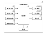
- the power supply 40 in addition to the above-mentioned electrodes 22L, 22R, 32L, 32R and operation units 28A, 28B, the power supply 40, the display unit 42, the contact detection unit 44, and the connection detection unit 46 , And a control unit 48.
- the power supply 40 of this embodiment is housed in the main body 12.
- the power source 40 is a primary battery such as a manganese battery, but may be a rechargeable secondary battery such as a lithium ion battery.
- the power supply 40 is electrically connected to the control unit 48, and supplies electric power to the plurality of electrodes 22L, 22R, 32L, and 32R via the control unit 48.
- the display unit 42 is configured by using, for example, a liquid crystal display, a plasma display, or the like.
- the display unit 42 displays information regarding the operation of the electrical stimulator 10.
- the display unit 42 of the present embodiment displays, for example, the output level of the electric stimulation power.
- the contact detection unit 44 detects the contact state of the user's body with respect to the pair of first electrodes 22L and 22R.
- the contact detection unit 44 is, for example, a load sensor, a touch sensor, a resistance detection circuit, or the like.
- the contact detection unit 44 is electrically connected to the control unit 48, and outputs a signal indicating the detection result to the control unit 48.
- the connection detection unit 46 detects the connection between the main body 12 and the attachments 14L and 14R by the connection members 16L and 16R.
- the connection detection unit 46 is, for example, a resistance detection circuit, a switch, a proximity sensor, or the like.
- the connection detection unit 46 is electrically connected to the control unit 48, and outputs a signal indicating the detection result to the control unit 48.
- the connection detection unit 46 of the present embodiment is individually provided corresponding to the plurality of connection members 16L and 16R, and detects the connection by the corresponding connection members 16L and 16R.
- connection detection unit 46 A case where a resistance detection circuit is used as the connection detection unit 46 will be described.
- the first electrodes 22L and 22R and the second electrodes 32L and 32R are not electrically connected by the connecting members 16L and 16R, and these The electrical resistance between them becomes close to infinity.
- the main body 12 and the fixtures 14L and 14R are connected by the connecting members 16L and 16R
- the first electrodes 22L and 22R and the second electrodes 32L and 32R are electrically connected by the connecting members 16L and 16R.
- the electrical resistance between them is smaller than in the case of.
- connection detection unit 46 When a resistance detection circuit is used for the connection detection unit 46, the resistance values of the first electrodes 22L and 22R and the second electrodes 32L and 32R are detected, and the resistance values and the threshold values are compared to obtain the connection members 16L and 16R. The connection can be detected.
- the control unit 48 of the present embodiment changes the operation of the electrical stimulator 10 in a different manner according to the pressing operation time of the operation units 28A and 28B.
- a pressing operation in which the pressing operation time of the operation units 28A and 28B is less than a predetermined threshold time (for example, 1.5 seconds) is called a short pressing operation, and a pressing operation in which the pressing operation time is longer than the predetermined threshold time is called a long pressing operation.
- the control unit 48 of the present embodiment reduces the output level of the electric stimulation power each time the first operation unit 28A is short-pressed, and increases the output level each time the second operation unit 28B is short-pressed. To do. Further, the control unit 48 of the present embodiment turns off the power supply 40 when the first operation unit 28A is long-pressed, and turns on the power supply 40 when the second operation unit 28B is long-pressed.
- the control unit 48 is electrically connected to a plurality of electrodes 22L, 22R, 32L, 32R and a power supply 40.
- the control unit 48 of the present embodiment is electrically connected to the plurality of first electrodes 22L, 22R and the power supply 40 via the internal wiring of the main body 12, and the internal wiring of the main body 12 is connected to the plurality of second electrodes 32L, 32R. It is electrically connected via the connecting members 16L and 16R.
- the control unit 48 applies electrical stimulation to the user's body by performing electrical stimulation control that controls electrical stimulation power supplied from the power supply 40 to the plurality of electrodes 22L, 22R, 32L, 32R.
- the electric power for electrical stimulation (hereinafter, also simply referred to as electric power) is, for example, an alternating current in a preset frequency range.
- the electric power for electrical stimulation may be, for example, a direct current. This frequency range is set to a range in which the user's muscles can be electrically stimulated.
- the electrical stimulation control is performed by supplying electric power of a predetermined output level to a plurality of electrodes 22L, 22R, 32L, and 32R according to a predetermined operation pattern. When using alternating current, the output level is determined using either the peak value or the effective value of the voltage.
- the control unit 48 sets a power supply destination from a plurality of electrodes 22L, 22R, 32L, and 32R, and supplies power to the set electrodes.
- the control unit 48 of the present embodiment sets a power supply destination from a plurality of electrodes 22L, 22R, 32L, 32R according to the presence or absence of connection between the main body 12 and the connecting members 16L, 16R of the fixtures 14L, 14R. To do. This setting method will be described later.
- the usage scenes of the present embodiment include a first usage scene using a plurality of first electrodes 22L and 22R of the main body 12 (see FIG. 4A), and first electrodes 22L and 22R of the main body 12 and a fixture 14L. , There is a second use scene (see FIG. 4B) using the second electrodes 32L and 32R of 14R.
- the user may take, for example, a standing posture, a sitting posture, or the like.
- the left and right feet are placed on each of the pair of first electrodes 22L and 22R.
- the left and right feet are applied to the pair of first electrodes 22L and 22R, respectively.
- the attachments 14L and 14R are attached to the user's body.
- the second electrodes 32L and 32R of the fixtures 14L and 14R are applied to the user's body.
- the control unit 48 of the electrical stimulator 10 starts the electrical stimulus control when the predetermined electrical stimulus start condition is satisfied (S10).
- the electrical stimulation start condition here is, for example, a long press operation of the second operation unit 28B when the power is on.
- control unit 48 When the control unit 48 starts the electrical stimulation control, the control unit 48 supplies power from the plurality of electrodes 22L, 22R, 32L, 32R depending on whether or not the main body 12 and the attachments 14L, 14R are connected by the connecting members 16L, 16R.
- the control unit 48 of the present embodiment sets the power supply destination based on the detection result of the connection detection unit 46.
- connection detection unit 46 detects the connection of the connection members 16L and 16R of the main bodies 12, 14L and 14R, and the connection detection unit 46 transmits a signal indicating the detection result. Is output to the control unit 48.
- the control unit 48 has a first closed circuit Ca that passes through a plurality of first electrodes 22L and 22R, provided that the main body 12 and the fixtures 14L and 14R are not connected by the connecting members 16L and 16R.
- the power supply destination is set so as to form.
- the control unit 48 of the present embodiment sets the power supply destination in this way on condition that the connection detection unit 46 detects that it is in this state.
- the first closed circuit Ca is a path that passes through at least two first electrodes 22L and 22R of the plurality of first electrodes 22L and 22R and does not pass through the second electrodes 32L and 32R.
- the control unit 48 sets a plurality of first electrodes 22L and 22R forming the first closed circuit Ca as power supply destinations.
- the mode of supplying electric power to the electrodes 22L and 22R set in this way is referred to as a first operation mode.
- the power supply destination is set so as to form the first closed circuit Ca passing through the left first electrode 22L and the right first electrode 22R.
- the left first electrode 22L and the right first electrode 22R are set as the power supply destinations for forming the first closed circuit Ca.
- the first closed circuit Ca serves as a path passing through the control unit 48, the left first electrode 22L, the right first electrode 22R, and the body.
- the "body” here includes the user's left leg, left thigh, hip, right thigh, and right leg in the present embodiment.
- FIG. 4 (B) assume a second usage scene as shown in FIG. 4 (B).
- the main body 12 and the left side mounting tool 14L are connected by the left side connecting member 16L
- the main body 12 and the right side mounting tool 14R are connected by the right side connecting member 16R.
- the control unit 48 passes through the first electrodes 22L and 22R and the second electrodes 32L and 32R, provided that the main body 12 and the fixtures 14L and 14R are connected by the connecting members 16L and 16R in this way.
- the power supply destination is set so as to form the second closed circuits CbL and CbR.
- the control unit 48 of the present embodiment sets the power supply destination in this way on condition that the connection detection unit 46 detects that it is in this state.
- the first electrodes 22L and 22R and the second electrodes 32L and 32R forming the second closed circuits CbL and CbR are provided on the main body 12 and the fixtures 14L and 14R to which the connecting members 16L and 16R are connected, respectively. It is electrically connected via the connecting members 16L and 16R.
- the second closed circuit CbL, CbR passes through the first electrodes 22L, 22R and the second electrodes 32L, 32R, which are electrically connected to each other, and is a different route from the first closed circuit Ca.
- the control unit 48 sets the first electrodes 22L and 22R and the second electrodes 32L and 32R forming the second closed circuits CbL and CbR as power supply destinations.
- the mode of supplying electric power to the electrodes 22L, 22R, 32L, and 32R set in this way is referred to as a second operation mode.
- the control unit 48 of the present embodiment sets the power supply destination so as to form a plurality of second closed circuits CbL and CbR.
- the plurality of second closed circuits CbL and CbR are paths that pass through the first electrodes 22L and 22R and the second electrodes 32L and 32R that are different from each other.
- the plurality of second closed circuits CbL and CbR of the present embodiment are set corresponding to each of the left and right halves of the user.
- the plurality of second closed circuits CbL and CbR include a left second closed circuit CbL corresponding to the left half of the body and a right second closed circuit CbR corresponding to the right half of the body.
- the left second closed circuit CbL passing through the left first electrode 22L and the left second electrode 32L, and the right second closed circuit CbR passing through the right first electrode 22R and the right second electrode 32R are formed.
- the left side first electrode 22L and the left side second electrode 32L are set as the power supply destinations for forming the left side second closed circuit CbL.
- the right side first electrode 22R and the right side second electrode 32R are set as the power supply destinations for forming the right side second closed circuit CbR.
- the left second closed circuit CbL serves as a path passing through the control unit 48, the left first electrode 22L, the left connecting member 16L, the left second electrode 32L, and the body.
- the “body” here includes the user's left foot and left thigh in the present embodiment.
- the right second closed circuit CbR serves as a path passing through the control unit 48, the right first electrode 22R, the right connecting member 16R, the right second electrode 32R, and the body.
- the "body” here includes the user's right foot and right thigh.
- At least one connecting member 16L and 16R is in a state where the main body 12 and the mounting tools 14L and 14R are connected. On condition that, the power supply destination is set in this way.
- the control unit 48 supplies electrical stimulation power to the electrodes 22L, 22R, 32L, and 32R, which are power supply destinations set in S12 (S14).
- the control unit 48 of the present embodiment ends the electrical stimulation control when it finishes supplying the electric stimulation power according to a predetermined operation pattern (S16).
- the electrical stimulator 10 of the present embodiment is attached to the lower body of the user and the second electrode in addition to the main body 12 provided with a pair of first electrodes 22L and 22R individually corresponding to the left and right feet, respectively.
- the fixtures 14L and 14R provided with 32L and 32R are provided. Therefore, in addition to the first closed circuit Ca formed by the pair of first electrodes 22L and 22R, the electric stimulation power is supplied to the second closed circuits CbL and CbR formed by the first electrodes 22L and 22R and the second electrodes 32L and 32R. Can be supplied.
- the intensity of electrical stimulation to the user's muscles tends to weaken as the energization path in the body becomes longer.
- the second electrodes 32L and 32R of the present embodiment are provided corresponding to the pair of first electrodes 22L and 22R, respectively. Therefore, the left second closed circuit CbL for the left half of the body can be formed by the left first electrode 22L corresponding to the left foot and the left second electrode 32L corresponding thereto. In addition to this, the right second closed circuit CbR for the right half of the body can be formed by the right first electrode 22R corresponding to the right foot and the corresponding right second electrode 32R. Therefore, when power is supplied to the second closed circuit CbL and CbR, the intensity of electrical stimulation to the muscles on both the second closed circuit CbL and CbR is higher than that when power is supplied to the first closed circuit Ca. It can be increased, and the sensation can be improved by electrical stimulation.
- the control unit 48 is mounted on a main body 12 placed on the floor surface FL, and the main body 12 and the fixtures 14L and 14R are connected by connecting members 16L and 16R. Therefore, even if the control unit 48 is not mounted on the fixtures 14L and 14R, the electric stimulation power can be supplied to the second electrodes 32L and 32R of the fixtures 14L and 14R via the connecting members 16L and 16R. Therefore, the weight of the fixtures 14L and 14R can be reduced, and the user can easily move even if the fixtures 14L and 14R are attached.
- the control unit 48 sets a power supply destination from a plurality of electrodes 22L, 22R, 32L, 32R according to the presence or absence of connection by the connection members 16L, 16R of the main bodies 12, 14L, 14R. Power is supplied to the set electrodes 22L, 22R, 32L, 32R. Therefore, in order to change the power supply destination from the plurality of electrodes 22L, 22R, 32L, and 32R, it is possible to eliminate the need to operate the operation units 28A and 28B of the main body 12, and good usability can be obtained.
- FIGS. 7 and 8 Most of the configurations of the left side second electrode 32L and the left side attachment 14L and the configuration of the right side second electrode 32R and the right side attachment 14R are common. Here, this common configuration will be described with reference to FIGS. 7 and 8 showing the former.
- the second electrodes 32L and 32R are provided on the back surface of the fixtures 14L and 14R.
- the second electrodes 32L and 32R of the present embodiment constitute an electrode pad that is applied to the skin surface of the body.
- the second electrodes 32L and 32R form a sheet as a whole.
- the second electrodes 32L and 32R have a base material 32a, a conductive portion 32b, an adhesive portion 32c, and a fixing portion 32d.
- the base material 32a has a sheet shape formed of, for example, a resin such as PET.
- the conductive portion 32b is configured by using a conductive material such as silver paste.
- the conductive portion 32b is provided on the side opposite to the fixtures 14L and 14R with respect to the base material 32a.
- the adhesive portion 32c is provided on the side opposite to the fixtures 14L and 14R with respect to the conductive portion 32b. Adhesive portions 32c will be provided on the back surfaces of the fixtures 14L and 14R. The adhesive portion 32c is detachably attached to the body. The fixtures 14L and 14R will be attached to the body via the adhesive portion 32c.
- the adhesive portion 32c of the present embodiment has conductivity, and is conducted to the conductive portion 32b by a conductive adhesive or the like. When the adhesive portion 32c of the second electrodes 32L and 32R is attached to the body, the conductive portion 32b and the skin surface of the body are conductive via the adhesive portion 32c.
- the adhesive portion 32c of the present embodiment is composed of an adhesive gel. As a result, the second electrodes 32L and 32R are less likely to be displaced with respect to the skin surface.
- the fixtures 14L and 14R have a fixed portion 50 to which the fixing portion 32d of the second electrodes 32L and 32R is detachably fixed.
- the fixed portion 32d and the fixed portion 50 of the present embodiment form a snap button in which a male snap and a female snap are combined.
- the fixed portion 50 is integrated with the fixtures 14L and 14R by sewing or the like.
- the second electrodes 32L and 32R are electrically connected to the control unit 48 via connecting members 16L and 16R connected to the fixed portion 50 of the fixtures 14L and 14R.
- the leg muscles are easy to move greatly by electrical stimulation, and also easy to move greatly by swinging the ankle.
- the attachments 14L and 14R are only attached to the body via the adhesive portion 32c, there is a high risk that the adhesive portion 32c will be peeled off from the body due to the movement of the muscles of the legs.
- the second electrodes 32L and 32R of the present embodiment are provided on the belt-shaped attachments 14L and 14R. Therefore, by wrapping the attachments 14L and 14R around the body, it becomes easy to avoid the situation where the adhesive portion 32c is peeled off from the body. Along with this, it becomes easier to maintain the state in which the second electrodes 32L and 32R are in contact with the body, and the conductive state of the second electrodes 32L and 32R with respect to the body can be stabilized.
- the belt-shaped attachments 14L and 14R have elasticity in the longitudinal direction. This may be realized by forming the attachments 14L and 14R with a stretchable material, or by providing the attachments 14L and 14R with an expansion and contraction portion such as a bellows structure. As a result, the fixtures 14L and 14R expand and contract in accordance with the movement of the leg muscles, so that it becomes easier to maintain the state in which the second electrodes 32L and 32R are in contact with the body.
- the back side fabric member 54 of the fixtures 14L and 14R is made of an airtight material.
- This material is, for example, a polyurethane film, chloroprene rubber, or the like.
- sweat generated from the body tends to be trapped on the back side of the fixtures 14L and 14R.
- the skin surface becomes easily moisturized at the portion where the second electrodes 32L and 32R hit the body, and the conduction state of the second electrodes 32L and 32R to the body becomes good.
- the back side fabric member 54 of the fixtures 14L and 14R may be configured to have higher elasticity than the front side fabric member 52.
- the back side fabric member 54 may be configured to have a larger elongation rate [%] than the front side fabric member 52.
- the elongation rate here means the ratio of the deformed dimension to the original dimension in that direction when a predetermined load is applied in the direction in which the elongation is most likely to occur.
- the knitting method of the fabrics constituting the front side fabric member 52 and the back side fabric member 54 and the Young's modulus of the fabric material may be changed.
- the back side fabric member 54 is larger than the case where the elasticity of the back side fabric member 54 is the same as that of the front side fabric member 52. While deforming, the deformation of the front side fabric member 52 can be suppressed. Along with this, changes in design and occurrence of wrinkles due to deformation of the front side fabric member 52 can be suppressed, and it becomes easy to avoid a situation in which the user feels uncomfortable due to the occurrence. Further, by suppressing the change in the appearance of the front side fabric member 52, it becomes easy to grasp the movement of the muscles of the body in the vicinity thereof, and it becomes easy to grasp how the body is moving due to the electrical stimulation.
- the electrical stimulator 10 of the second embodiment includes a heater 60.
- the heater 60 of this embodiment is mounted on the main body 12.
- the heater 60 is, for example, a sheathed heater, a cartridge heater, or the like.
- the heater 60 of the present embodiment is arranged at a position where the contact point of the user's body on the main body 12 can be heated when an electric stimulus is applied to the muscle of the user.
- the "contact points" are the electrodes 22L and 22R of the main body 12.
- the "contact points" are the footrests 18L and 18R of the main body 12 in the present embodiment.
- the heater 60 of the present embodiment is arranged inside the main body 12 on the back side of the footrest portions 18L and 18R (first electrodes 22L and 22R).
- a part of the body in contact with the main body 12 can be warmed by the heater 60, and the blood flow of the body can be promoted at the warmed part.
- it becomes easy to dilate the blood vessels of the body at the warmed part and it becomes easy to suppress the electric resistance when the electric current flows through the blood vessels.
- the heater 60 may be mounted on the fixtures 14L and 14R. In this case as well, the heater 60 may heat the contact points of the user's body on the fixtures 14L and 14R when applying electrical stimulation to the user's muscles.
- the electrical stimulator 10 of the third embodiment includes light sources 62L and 62R mounted on the main body 12. Although the light sources 62L and 62R of this embodiment are mounted on the main body 12, they may be mounted on the fixtures 14L and 14R. The light sources 62L and 62R have a role of notifying the operation of the electrical stimulator 10.
- the light sources 62L and 62R are, for example, LEDs, discharge lamps, incandescent bulbs, and the like.
- the light sources 62L and 62R of the present embodiment are provided at a position where the lighting state can be visually recognized on the upper surface portion of the main body 12.
- the housing 24 of the main body 12 is provided with peripheral portions 64L and 64R on the peripheral edges of the first electrodes 22L and 22R (foot rest portions 18L and 18R).
- the peripheral edge portions 64L and 64R include a left peripheral edge portion 64L provided on the peripheral edge of the left side first electrode 22L and a right peripheral edge portion 64R provided on the peripheral edge of the right side first electrode 22R.
- the light sources 62L and 62R of the present embodiment include a left light source 62L corresponding to the left first electrode 22L and a right light source 62R corresponding to the right first electrode 22R.
- the left light source 62L is provided on the left peripheral edge 64L of the main body 12, and the right light source 62R is provided on the right peripheral edge 64R of the main body 12.
- the light sources 62L and 62R are provided so as to be located on a line along the peripheral portions 64L and 64R of the main body 12.
- the individual light sources 62L and 62R are continuously provided on the line, but may be provided discretely on the line at intervals.
- the control unit 48 controls the lighting state of the light sources 62L and 62R in conjunction with the supply of electrical stimulation power to the first electrodes 22L and 22R of the main body 12. Specifically, when power is being supplied to the first electrodes 22L and 22R, the light sources 62L and 62R corresponding to the first electrodes 22L and 22R are turned on. When power is being supplied to the left first electrode 22L, the left light source 62L corresponding to the left first electrode 22L is turned on. When power is being supplied to the right first electrode 22R, the right light source 62R corresponding to the right first electrode 22R is turned on. In order to light the light sources 62L and 62R in this way, the light sources 62L and 62R may be continuously turned on, or the light sources 62L and 62R may be blinked.
- the control unit 48 may control the lighting state of the light sources 62L and 62R in conjunction with the output level of the electric stimulation power. For example, consider the case of using light sources 62L and 62R whose amount of light can be changed. In this case, the control unit 48 may increase the amount of light of the light sources 62L and 62R as the output level increases, and decrease the amount of light of the light sources 62L and 62R as the output level decreases.
- control unit 48 may bring the wavelengths of the light sources 62L and 62R closer to one end side of the wavelength region as the output level increases, and may bring the wavelengths of the light sources 62L and 62R closer to the other end side of the wavelength region as the output level decreases. ..
- control unit 48 brings the blinking speeds of the light sources 62L and 62R closer to one end side (for example, the slowing side) of the variable range as the output level increases, and the other end side (for example) of the variable range as they decrease. , The side to speed up) may be approached.
- control unit 48 may control the light sources 62L and 62R in the same manner as the output level in conjunction with the frequency of the electric stimulation power as an alternative to the output level.
- the electrical stimulator 10 of the fourth embodiment has different configurations of the fixtures 14L and 14R as compared with the first embodiment.
- the attachments 14L and 14R of the present embodiment are footwear 66 that can be attached by being worn on the user's foot.
- socks are shown as an example of the footwear 66.
- the footwear 66 constituting the right side attachment 14R is shown, but the left side attachment 14L is also composed of the footwear 66.
- the footwear 66 of the present embodiment includes a bottom portion 66a that covers the entire sole of the user, an instep covering portion 66b that covers the instep of the user, a heel covering portion 66c that covers the user's heel from both the left and right sides and the rear side, and the user's footwear 66.
- a thigh cover portion 66d that covers the thigh is provided.
- a conductive portion 66e is provided on the bottom portion 66a of the footwear 66.
- hatching is provided at a portion that becomes the conductive portion 66e.
- the conductive portion 66e is configured by using a conductive material such as a conductive fiber.
- the user's foot Ft is conducted with respect to the first electrodes 22L and 22R via the conductive portion 66e of the footwear 66.
- a portion different from the bottom 66a of the footwear 66 constitutes an insulating portion 66f.
- the insulating portion 66f is configured by using an insulating material such as an insulating fiber.
- the insulating portion 66f of the present embodiment is composed of the instep covering portion 66b, the heel covering portion 66c, and the thigh covering portion 66d of the attachments 14L and 14R.
- the second electrodes 32L and 32R of the present embodiment are provided inside the thigh covering portion 66d of the footwear 66.
- the second electrodes 32L and 32R will be provided at a location different from the bottom 66a of the footwear 66. It can be said that the second electrodes 32L and 32R are provided inside the insulating portion 66f of the footwear 66.
- the second electrodes 32L and 32R of the present embodiment form an annular shape so as to come into contact with the thighs of the body over the entire circumference. It can be said that the second electrodes 32L and 32R have a shape of contacting the thigh of the body over a range of more than half a circumference. This facilitates the formation of a closed circuit that passes through the thighs of the body in a wide range below the contact positions of the second electrodes 32L and 32R with respect to the body.
- the connecting members 16L and 16R are detachably connected to the footwear 66 via the second connector 68.
- the second connector 68 is provided at the end of the electric cable 34 of the connecting members 16L and 16R, and the footwear 66 is provided with a second receiving portion 70 to which the connecting members 16L and 16R are connected via the second connector 68.
- the second connector 68 is a male snap and the second receiving portion 70 is a female snap, which constitute a snap button.
- the second receiving portion 70 is integrated with the footwear 66 by sewing or the like.
- the second electrodes 32L and 32R are electrically connected to the control unit 48 (not shown) via the second receiving portion 70 of the footwear 66 and the connecting members 16L and 16R.
- the user can use the electric stimulator 10 without being barefoot, and the trouble of taking off the footwear 66 can be eliminated. Further, depending on the usage environment of the electric stimulator 10, the user may be restricted from being barefoot, and even in such a case, the user can use the electric stimulator 10.
- the above footwear 66 is preferably made of a highly airtight and flexible material such as polyurethane.
- a highly airtight and flexible material such as polyurethane.
- the heat retention and moisture retention of the footwear 66 are enhanced, the moisture content of the skin is increased at the place where the footwear 66 (socks) is worn, and the electric resistance at the place where the footwear 66 is worn can be suppressed.
- the intensity of the electrical stimulation to the muscles of the portion where the footwear 66 is worn can be increased, and the sensation of the electrical stimulation can be improved.
- the shapes of the second electrodes 32L and 32R are not particularly limited when they are provided on the thigh covering portion 66d of the footwear 66.
- the second electrodes 32L and 32R may be in contact with the thighs of the body within a range of less than half a circumference.
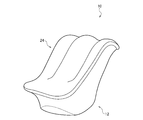
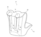
- the electrical stimulator 10 of the present embodiment mainly differs in the configuration of the main body 12.
- the main body 12 includes a housing 24 that forms a storage space 72 that accommodates the user's left and right feet.
- the housing 24 is made of a hard synthetic resin or the like.
- the accommodation space 72 of the present embodiment can accommodate a part of the thigh in addition to the user's foot.
- the pair of first electrodes 22L and 22R described above form an accommodation space 72 of the main body 12. The same applies to the pair of footrests 18L and 18R described above.
- a pair of insertion ports 74 for inserting the user's feet are formed on the upper surface portion on the rear side of the housing 24.
- a continuous opening 76 is formed in each of the pair of insertion ports 74 on the rear surface portion of the housing 24.
- the main body 12 includes a cover body 78 that covers the opening 76 of the housing 24.
- the cover body 78 is made of a synthetic resin or fiber softer than the housing 24.
- the cover body 78 is provided with an opening / closing tool 80 such as a wire fastener capable of opening / closing the cover body 78.
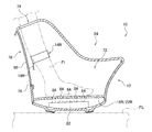
- the electrical stimulator 10 of the present embodiment further includes a germicidal lamp 82 that irradiates the accommodation space 72 with germicidal light.
- the sterilizing light is light in a wavelength range having a sterilizing effect such as ultraviolet rays.
- the germicidal lamp 82 of the present embodiment is arranged on the back side of the footrests 18L and 18R of the main body 12 and inside the main body 12.
- the footrests 18L and 18R of the main body 12 of the present embodiment are provided with a translucent portion 84 capable of transmitting sterilizing light.
- the translucent portion 84 of the present embodiment is a through hole penetrating the footrest portions 18L and 18R.
- the translucent portion 84 may be made of a translucent material capable of transmitting sterilizing light.
- the germicidal lamp 82 can suppress the growth of bacteria caused by the sweat, and good hygiene can be obtained.
- the sterilizing light is irradiated into the accommodation space 72 of the main body 12, the sterilizing light is less likely to leak to the outside of the main body 12. Along with this, it is possible to avoid the situation where the sterilizing light is seen with the naked eye, and the burden on the user's eyes can be suppressed. Further, since the germicidal light does not easily leak to the outside of the main body 12, there is an advantage that the output of the germicidal lamp 82 can be easily increased.
- the germicidal lamp 82 may be arranged at a position where the germicidal light can be applied to a part of the body other than the soles of the feet placed on the footrests 18L and 18R.
- This part of the body means a part accommodated in the accommodation space 72 of the main body 12.
- This part of the body includes, for example, the instep and heel of the foot other than the sole of the foot, as well as the lower leg and the like.
- the germicidal lamp 82 may be arranged at a position where the germicidal lamp 82 can be irradiated to the entire accommodation space 72. In this case, the sterilizing light is applied to the entire exposed portion of the body part of the accommodation space 72 that is accommodated in the accommodation space 72. In any case, the germicidal lamp 82 can irradiate the feet accommodated in the accommodation space 72 with germicidal light.
- the control unit 48 of the electrical stimulator 10 may control the germicidal lamp 82 so as to irradiate the germicidal lamp in conjunction with the supply of the electrical stimulation power to the plurality of electrodes 22L, 22R, 32L, 32R.
- the sterilizing light may be irradiated during the supply of the electric stimulation electric power, or the sterilizing light may be irradiated for a predetermined time after the supply of the electric stimulation electric power is completed.
- the fixtures 14L and 14R of the present embodiment are attached to the user's body in the accommodation space 72 of the main body 12.
- the "user's body” here is the lower leg of the user in the present embodiment.
- the connecting members 16L and 16R of the present embodiment are arranged so as to pass only the inside of the main body 12 without passing through the outside. As the inside of the main body 12, it is arranged so as to pass through at least the accommodation space 72 of the main body 12. As a result, the fixtures 14L and 14R and the connecting members 16L and 16R are not exposed to the outside of the main body 12, and the electrical stimulator 10 having a neat appearance can be realized.
- the electrical stimulator 10 of the present embodiment is different from the fifth embodiment in that the fixtures 14L and 14R and the connecting members 16L and 16R.
- the attachments 14L and 14R of the present embodiment are attached to the user's body outside the accommodation space 72 of the main body 12.
- the "user's body” here is the user's upper thigh in the present embodiment.
- the connecting members 16L and 16R of the present embodiment are arranged outside the main body 12.
- the positions of the fixtures 14L and 14R and the connecting members 16L and 16R are not particularly limited.
- the electrical stimulator 10 of the present embodiment is different from the fifth embodiment in that it includes a blower 86.
- the blower unit 86 includes a heat exchanger 88 that changes the temperature of the air taken in from the outside of the main body 12, and a fan 90 that supplies the air whose temperature has been changed by the heat exchanger 88 into the accommodation space 72.
- the heat exchanger 88 of the present embodiment can heat the outside air, and the fan 90 supplies the heated air into the accommodation space 72.
- the amount of water in the skin of a part of the body increases at the place where it is housed, and the electrical resistance at that place can be suppressed.
- the intensity of the electrical stimulation to the muscles of the portion housed in the storage space 72 can be increased, and the sensation of the electrical stimulation can be improved.
- the heat exchanger 88 may be able to cool the outside air.
- the fan 90 supplies the cooled air into the accommodation space 72.
- the blower portion 86 may be configured not to include the heat exchanger 88.
- the user can feel the coolness by blowing the wind on the feet in the accommodation space 72 of the main body 12, and the electric stimulator 10 can be easily used in a high temperature environment.
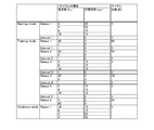
- the operation indicated by "Status” is to repeat the operation of a predetermined cycle by the "number of cycles" of the line to which each "Status” belongs.
- This "predetermined cycle” is an operation in which the operations of the plurality of lines to which the "Status” belongs are performed in order from the top line.
- This "operation of multiple lines” is an operation of supplying alternating current to a plurality of electrodes 22L, 22R, 32L, 32R for the "required time” of the same line at the "frequency” of the referred line. Is.
- the operation indicated by "Interval” is an operation of stopping the supply of alternating current to the plurality of electrodes 22L, 22R, 32L, and 32R for the "required time” of the row to which each "Interval” in FIG. 17 belongs.
- FIG. 17 mainly shows an operation pattern in which the following alternating currents (1), (2), and (3) are combined.
- (1) is an alternating current suitable for loosening muscles.
- (2) is an alternating current suitable for strength training.
- (3) is an alternating current suitable for imparting a physical sensation due to electrical stimulation.
- FIG. 17 shows an operation mode for strength training in which the alternating current of (2) is combined.
- (1) Alternating current in a predetermined frequency band (less than 15 Hz) suitable for promoting simple contraction in muscles (2)
- FIG. 18 is an operation pattern in which the above-mentioned (1) and (3) are combined.
- FIG. 18 shows an operation mode for healthcare that mainly uses the alternating current of (1) without using the alternating current of (2).
- the fixtures 14L and 14R may be attached to the lower body of the user.
- the attachments 14L and 14R may be attached to the waist in addition to the user's thighs.
- the attachments 14L and 14R are attached to the upper thighs of both legs in the examples of FIGS. 4 (B) and 19 (described later).
- the attachments 14L and 14R may be attached to either the shins or ankles of both legs, that is, the lower legs of both legs.
- the main body 12 may be attached to the user. That is, the main body 12 may be placed on the floor surface or may be attached to the user.
- the fixtures 14L and 14R may be attached to a place other than the lower body of the user, that is, the upper body.
- the number of fixtures 14L and 14R is not particularly limited.
- the fixtures 14L and 14R may be singular or three or more.
- the mounting mode of the main body 12 and the fixtures 14L and 14R on the body is not particularly limited. This mounting mode is, for example, winding, hooking, pasting, or the like.
- the shapes of the main body 12 and the fixtures 14L and 14R are not particularly limited. For example, it may be a planar structure having a shape that can be attached only to the front surface or the rear surface of the user.
- first electrodes 22L and 22R may be provided as the plurality of first electrodes 22L and 22R.
- the first electrodes 22L and 22R may be provided separately from the footrest portions 18L and 18R.
- a pad covering the instep may be provided on the main body 12 above the foot rests 18L and 18R, and the first electrodes 22L and 22R may be provided on the pad.
- a pad for covering the heel of the foot from the rear side may be provided behind the foot rests 18L and 18R, and the first electrodes 22L and 22R may be provided on the pad.
- the number of the second electrodes 32L and 32R provided on the fixtures 14L and 14R is not limited, and only a single second electrode 32L and 32R may be provided, or three or more second electrodes 32L and 32R may be provided. May be done.
- the plurality of second electrodes 32L, 32R corresponding to the plurality of first electrodes 22L, 22R may be provided on a single fixture 14L, 14R, or may be provided on individual fixtures 14L, 14R.
- the adhesive portion 32c of the fixtures 14L and 14R may be provided at a location different from the second electrodes 32L and 32R.
- it may be provided on the back surface of the fixtures 14L and 14R at a location other than the second electrodes 32L and 32R.
- the first electrodes 22L and 22R are provided on the main body 12.
- the connecting members 16L and 16R are detachably connected to the main body 12
- they may be detachably connected to the fixtures 14L and 14R, or may be detachably connected to both main bodies 12, 14L and 14R. May be.
- a member different from the electric cable 34 may be provided.
- This "another member” is, for example, a controller on which the control unit 48 is mounted.
- the connecting members 16L and 16R may include an electric cable for connecting the controller and the main body 12, an electric cable for connecting the controller and the fixtures 14L and 14R, and a controller.
- the plurality of connecting members 16L and 16R corresponding to the plurality of attachments 14L and 14R may be connected to the main body 12 via a single first connector 36.
- the power supply 40 may be housed in the fittings 14L and 14R, or may be provided outside the main body 12 and the fittings 14L and 14R.
- the power source 40 may be configured by an external power source such as a commercial power source provided separately from the electrical stimulator 10.
- the control unit 48 may be mounted on the fixtures 14L and 14R, or may be mounted on a member different from the main body 12 and the fixtures 14L and 14R.
- the control unit 48 may be able to independently change the output level of the electric stimulation power for each of the plurality of closed circuits.
- the left side second closed circuit CbL and the right side second closed circuit CbR may be changed independently.
- the electrical stimulator 10 may include an operation unit for switching the closed circuit to which the output level is changed.
- the electrical stimulator 10 causes another control unit that switches the power supply 40 from off to on, triggered by the contact detection unit 44 detecting that the user's body has come into contact with the pair of first electrodes 22L and 22R. You may have it.
- an auxiliary power source different from the above-mentioned power source 40 may be mounted on the main body 12, and the contact detection unit 44 and other control units may operate based on the auxiliary power source.
- the electrical stimulator 10 may include a notification unit that notifies the operation of the electrical stimulator 10 by sound.
- This notification unit is, for example, a speaker or the like.
- the notification unit may notify that the electrical stimulation device 10 has started the electrical stimulation control or has finished the electrical stimulation control. In addition to this, it may be notified that an input has been received to the operation units 28A and 28B of the electric stimulator 10.
- the operation on the electrical stimulator 10 may be performed through the operation on the remote controller.
- the remote controller may be dedicated to the electrical stimulator 10 or may be a general-purpose information processing terminal incorporating an application capable of operating the electrical stimulator 10.
- the electric stimulator 10 may include a conductive material arranged separately from the electrodes between the electrodes and the body.
- the conductive material is, for example, a conductive fiber, a conductive rubber, or the like.
- the attachments 14L, and 14R of the electric stimulator 10 are attached to the body, they do not have to be directly attached to the user's body.
- the innerwear is worn on the body, the innerwear is partially provided with a conductive material at the place where the electrodes of the main body 12, the fixtures 14L and 14R hit, and the main body 12 and the fixtures 14L are placed on the innerwear. , 14R may be attached. This allows you to train without taking off your innerwear.
- the second electrodes 32L and 32R By changing the positions of the second electrodes 32L and 32R that come into contact with the body, it is possible to change the sensation when electrical stimulation is applied.
- strong electrical stimulation can be applied to the quadriceps femoris.
- strong electrical stimulation can be applied to the muscles in the range from the shin to the foot on the premise that the first electrodes 22L and 22R of the main body 12 are applied to the foot.
- a strong electrical stimulation can be applied to the hamstring.
- strong electrical stimulation can be applied to the muscles in the range from the calf to the foot on the premise that the first electrodes 22L and 22R of the main body 12 are applied to the foot.
- strong electrical stimulation can be applied to the calf muscle
- the second electrodes 32L and 32R are applied to the shin of the lower leg, strong electrical stimulation can be applied to the shin muscle.
- FIG. 19 shows a third use scene of the electrical stimulator 10 of the first embodiment.
- the first electrodes 22L and 22R of the main body 12 are not used, but the second electrodes 32L and 32R of the fixtures 14L and 14R are used.
- the attachments 14L and 14R are attached to the user's body as in the second usage scene.
- the second electrodes 32L and 32R of the fixtures 14L and 14R are applied to the user's body.
- the main body 12 and the fixtures 14L and 14R are connected by the connecting members 16L and 16R.
- a third closed circuit Cc passing through the plurality of second electrodes 32L and 32R is formed.
- the third closed circuit Cc is a path that does not pass through the plurality of first electrodes 22L and 22R and passes through the control unit 48, the left second electrode 32L, the right second electrode 32R, and the body.
- the "body” here includes the left thigh, the waist, and the right thigh in the present embodiment.
- the control unit 48 may set the power supply destination as follows. In both the second usage scene (see FIG. 4B) and the third usage scene, the main body 12 and the fixtures 14L and 14R are in a state of being connected by the connecting members 16L and 16R. On condition that it is in this state, the control unit 48 sets the power supply destination so as to form any of the second closed circuit CbL, CbR, and the third closed circuit Cc in S12.
- the electrode to be supplied with electric power may be selected by the user through an operation on an operation unit (for example, operation units 28A and 28B) of the electrical stimulator 10. At this time, the user selects an electrode to be a power supply destination from the electrodes corresponding to any of the second closed circuit CbL, CbR and the third closed circuit Cc.
- the electrode to which the electric power is supplied may be selected by the user in advance before starting the electrical stimulation control.
- the control unit 48 may request an electrode to be selected by the user after starting the electrical stimulation control.
- the first electrodes 22L and 22R and the second electrodes 32L and 32R are set as power supply destinations as the electrodes corresponding to the second closed circuits CbL and CbR.
- the second electrodes 32L and 32R are set as power supply destinations as the electrodes corresponding to the third closed circuit Cc.
- any combination of the above components is also effective as an aspect of the present invention.
- any explanatory matter of the modified example may be combined with the embodiment, or arbitrary explanatory matter of the embodiment and other modified examples may be combined with the modified example. An example of this combination will be described.
- the heater 60 of the second embodiment, the light sources 62L and 62R of the third embodiment, the socks of the fourth embodiment, the germicidal lamp 82 of the fifth embodiment, and the blower 86 of the seventh embodiment are electrics of other embodiments. It may be combined with the stimulator 10. Further, the electrical stimulator 10 of the fifth and seventh embodiments may be used as if the fixtures 14L and 14R and the second electrodes 32L and 32R are omitted.
- the main body 12 includes a housing 24 that forms an accommodation space 72.
- the heater 60 may be arranged at a position where the accommodation space 72 of the main body 12 can be heated. Even in this case, a part of the body in the accommodation space 72 can be heated by the heater 60, and the blood flow of the body can be promoted at the heated portion.
- the intensity of the electrical stimulation to the muscles around the warmed part can be easily increased, and the sensation of the electrical stimulation can be improved.
- the heater 60 may be arranged at a position where the main body 12 can heat the accommodation space 72.
- the second electrodes 32L and 32R of the fixtures 14L and 14R can also be heated by the heater 60. If the second electrodes 32L and 32R, whose temperature is lower than that of the body, come into contact with the body for a long period of time, the user may feel uncomfortable due to a feeling of coldness. In this respect, according to such a configuration, the temperature difference from the body can be reduced by warming the second electrodes 32L and 32R, and it becomes easy to avoid a situation in which the user is uncomfortable due to a feeling of coldness.
- An electrical stimulator that applies electrical stimulation to a user's muscles, the main body, a plurality of first electrodes provided on the main body, an attachment attached to the user's body, and the attachment.
- the second electrode provided, the control unit that controls the electric stimulation power supplied from the power source to the plurality of first electrodes and the second electrode, the main body and the fixture are connected, and the power is transmitted.
- a connecting member is provided, the connecting member is detachably connected to at least one of the main body and the fitting, and the control unit is connected to the main body and the fitting by the connecting member.
- An electrical stimulator that sets a power supply destination from the plurality of first electrodes and the second electrode accordingly, and supplies the power to the set electrodes.
- the inventor of the present application has obtained the recognition that there is room for improvement in terms of usability in applying electrical stimulation using electrodes of a plurality of main bodies.
- the present invention relates to an electrical stimulator.
- 10 Electrical stimulator, 12 ... Main body, 14L, 14R ... Fixture, 16L, 14R ... Connection member, 22L, 22R ... First electrode, 32L, 32R ... Second electrode, 40 ... Power supply, 46 ... Connection detector, 48 ... Control unit.
Landscapes
- Health & Medical Sciences (AREA)
- Engineering & Computer Science (AREA)
- Biomedical Technology (AREA)
- Nuclear Medicine, Radiotherapy & Molecular Imaging (AREA)
- Radiology & Medical Imaging (AREA)
- Life Sciences & Earth Sciences (AREA)
- Animal Behavior & Ethology (AREA)
- General Health & Medical Sciences (AREA)
- Public Health (AREA)
- Veterinary Medicine (AREA)
- Electrotherapy Devices (AREA)
Abstract
L'invention concerne un dispositif d'électrostimulation qui permet d'obtenir une amélioration de la sensation physique par l'électrostimulation. Le dispositif d'électrostimulation qui confère une électrostimulation aux muscles d'un utilisateur comprend : une unité principale (12) ; une paire de premières électrodes (22L et 22R) reliées à l'unité principale (12) sous forme d'unités indépendantes, la paire de premières électrodes (22L et 22R) correspondant respectivement aux jambes gauche et droite de l'utilisateur ; des raccords (14L et 14R) qui sont fixés à la partie inférieure du corps de l'utilisateur ; des secondes électrodes (32L et 32R) qui sont reliées aux raccords (14L et 14R) ; et une unité de commande (48) qui régule l'énergie électrique fournie pour l'électrostimulation par une source d'alimentation à la paire de premières électrodes (22L et 22R) et de secondes électrodes et de secondes électrodes (32L et 32R).
Priority Applications (1)
| Application Number | Priority Date | Filing Date | Title |
|---|---|---|---|
| JP2021509633A JPWO2020196830A1 (fr) | 2019-03-28 | 2020-03-27 |
Applications Claiming Priority (2)
| Application Number | Priority Date | Filing Date | Title |
|---|---|---|---|
| JP2019064553 | 2019-03-28 | ||
| JP2019-064553 | 2019-03-28 |
Publications (1)
| Publication Number | Publication Date |
|---|---|
| WO2020196830A1 true WO2020196830A1 (fr) | 2020-10-01 |
Family
ID=72611569
Family Applications (1)
| Application Number | Title | Priority Date | Filing Date |
|---|---|---|---|
| PCT/JP2020/014003 Ceased WO2020196830A1 (fr) | 2019-03-28 | 2020-03-27 | Dispositif d'électrostimulation |
Country Status (2)
| Country | Link |
|---|---|
| JP (1) | JPWO2020196830A1 (fr) |
| WO (1) | WO2020196830A1 (fr) |
Citations (7)
| Publication number | Priority date | Publication date | Assignee | Title |
|---|---|---|---|---|
| JPH1157028A (ja) * | 1997-08-09 | 1999-03-02 | Izumi Denshi Kk | 電子治療器の電気パルス発信制御方法 |
| JPH11114074A (ja) * | 1997-10-08 | 1999-04-27 | Ya Man Ltd | パルス美容器の電極タイツ |
| JPH11192283A (ja) * | 1997-12-27 | 1999-07-21 | Ya Man Ltd | 足裏マッサージ器の電極ソックス |
| JPH11347097A (ja) * | 1998-06-05 | 1999-12-21 | Ya Man Ltd | 足裏マッサージ器 |
| JP2004329606A (ja) * | 2003-05-08 | 2004-11-25 | Interport International Kk | 足裏治療装置 |
| JP2018508326A (ja) * | 2015-02-15 | 2018-03-29 | ジヴ ヘルスケア リミテッド | 心拍変動性を改善するためのシステム及び方法 |
| JP2018183481A (ja) * | 2017-04-27 | 2018-11-22 | 株式会社 Mtg | 筋肉電気刺激装置 |
Family Cites Families (5)
| Publication number | Priority date | Publication date | Assignee | Title |
|---|---|---|---|---|
| JPS54170691U (fr) * | 1978-05-23 | 1979-12-03 | ||
| EP0440719A1 (fr) * | 1988-10-31 | 1991-08-14 | FAKHRI, Omar | Appareil et procede electrotherapeutique |
| JPH11332953A (ja) * | 1998-05-22 | 1999-12-07 | Ya Man Ltd | 痩身被服 |
| JP2003180845A (ja) * | 2001-12-14 | 2003-07-02 | Ya Man Ltd | トリートメント装置 |
| WO2013075270A1 (fr) * | 2011-11-25 | 2013-05-30 | Yang Chang-Ming | Objet, procédé, et système servant à détecter un battement de cœur ou à déterminer si des électrodes sont en contact correct |
-
2020
- 2020-03-27 WO PCT/JP2020/014003 patent/WO2020196830A1/fr not_active Ceased
- 2020-03-27 JP JP2021509633A patent/JPWO2020196830A1/ja active Pending
Patent Citations (7)
| Publication number | Priority date | Publication date | Assignee | Title |
|---|---|---|---|---|
| JPH1157028A (ja) * | 1997-08-09 | 1999-03-02 | Izumi Denshi Kk | 電子治療器の電気パルス発信制御方法 |
| JPH11114074A (ja) * | 1997-10-08 | 1999-04-27 | Ya Man Ltd | パルス美容器の電極タイツ |
| JPH11192283A (ja) * | 1997-12-27 | 1999-07-21 | Ya Man Ltd | 足裏マッサージ器の電極ソックス |
| JPH11347097A (ja) * | 1998-06-05 | 1999-12-21 | Ya Man Ltd | 足裏マッサージ器 |
| JP2004329606A (ja) * | 2003-05-08 | 2004-11-25 | Interport International Kk | 足裏治療装置 |
| JP2018508326A (ja) * | 2015-02-15 | 2018-03-29 | ジヴ ヘルスケア リミテッド | 心拍変動性を改善するためのシステム及び方法 |
| JP2018183481A (ja) * | 2017-04-27 | 2018-11-22 | 株式会社 Mtg | 筋肉電気刺激装置 |
Also Published As
| Publication number | Publication date |
|---|---|
| JPWO2020196830A1 (fr) | 2020-10-01 |
Similar Documents
| Publication | Publication Date | Title |
|---|---|---|
| JP7608537B2 (ja) | 電気刺激装置 | |
| US20200085116A1 (en) | Combination Vibrational And Thermal Jumper | |
| US10362812B2 (en) | Fabric device | |
| KR20190016047A (ko) | 신체에 전류를 전달하기 위한 디바이스들 및 치료를 위한 관련 방법들 | |
| US20110030199A1 (en) | Electric heating/warming fabric articles | |
| WO2012034416A1 (fr) | Vêtement chauffant électrique | |
| CN118415407A (zh) | 电刺激健身衣 | |
| CN103845790B (zh) | 远红外低压电热磁疗中药理疗带 | |
| JP2007529238A (ja) | 加熱衣料システム | |
| WO2020196830A1 (fr) | Dispositif d'électrostimulation | |
| US12102143B2 (en) | Combination vibrational and thermal jumper | |
| CN208064517U (zh) | 一种适于坐轮椅老年人穿着的功能服装 | |
| US20110046703A1 (en) | Heating device for low voltage thermal therapy | |
| CN101444341A (zh) | 一种多功能水疗鞋 | |
| US20040059387A1 (en) | Low frequency acupuncture point electrically stimulating device | |
| JPH09327521A (ja) | 電気刺激装置 | |
| CN103800117A (zh) | 适用于贴身穿着的电控型热敷装置 | |
| KR20100049382A (ko) | 이코노미 클래스 증후군 예방용 하지 근육 전기자극기 | |
| CN211674831U (zh) | 一种风湿免疫性腰膝疾病治疗装置 | |
| CN104887498A (zh) | 一种脚部艾灸服 | |
| JP2023086884A (ja) | 電気刺激装置 | |
| KR20190070802A (ko) | 바지형태의 휴대용 좌훈기 | |
| CN201353234Y (zh) | 低电压热疗用加热装置 | |
| CN210673541U (zh) | 暖宫养巢臀疗裤 | |
| CN201356113Y (zh) | 一种多功能水疗鞋 |
Legal Events
| Date | Code | Title | Description |
|---|---|---|---|
| 121 | Ep: the epo has been informed by wipo that ep was designated in this application |
Ref document number: 20779856 Country of ref document: EP Kind code of ref document: A1 |
|
| ENP | Entry into the national phase |
Ref document number: 2021509633 Country of ref document: JP Kind code of ref document: A |
|
| NENP | Non-entry into the national phase |
Ref country code: DE |
|
| 122 | Ep: pct application non-entry in european phase |
Ref document number: 20779856 Country of ref document: EP Kind code of ref document: A1 |