WO2020196830A1 - 電気刺激装置 - Google Patents
電気刺激装置 Download PDFInfo
- Publication number
- WO2020196830A1 WO2020196830A1 PCT/JP2020/014003 JP2020014003W WO2020196830A1 WO 2020196830 A1 WO2020196830 A1 WO 2020196830A1 JP 2020014003 W JP2020014003 W JP 2020014003W WO 2020196830 A1 WO2020196830 A1 WO 2020196830A1
- Authority
- WO
- WIPO (PCT)
- Prior art keywords
- electrodes
- main body
- user
- fixtures
- control unit
- Prior art date
- Legal status (The legal status is an assumption and is not a legal conclusion. Google has not performed a legal analysis and makes no representation as to the accuracy of the status listed.)
- Ceased
Links
Images


Classifications
-
- A—HUMAN NECESSITIES
- A61—MEDICAL OR VETERINARY SCIENCE; HYGIENE
- A61N—ELECTROTHERAPY; MAGNETOTHERAPY; RADIATION THERAPY; ULTRASOUND THERAPY
- A61N1/00—Electrotherapy; Circuits therefor
- A61N1/18—Applying electric currents by contact electrodes
- A61N1/32—Applying electric currents by contact electrodes alternating or intermittent currents
- A61N1/36—Applying electric currents by contact electrodes alternating or intermittent currents for stimulation
Definitions
- the present invention relates to an electrical stimulator.
- Patent Document 1 describes an electrical stimulator in which a pair of foot electrodes corresponding to the left and right feet are provided in the main body.
- the present inventor examined the electrical stimulator of Patent Document 1. As a result, it was recognized that there is room for improvement in improving the sensation of the electrical stimulation when the electrical stimulation is applied using the main body provided with the pair of foot electrodes.
- a certain aspect of the present invention is made in view of such a problem, and one of the purposes thereof is to provide an electric stimulator capable of improving the sensation by electric stimulation.
- an electrical stimulation device that applies electrical stimulation to a user's muscles, and the main body and the left and right feet of the user are individually attached to the main body.
- a pair of first electrodes provided and applied to the corresponding feet, a fitting attached to the lower body of the user, a second electrode provided on the fitting, and the pair of first electrodes and the second electrode.
- It includes a control unit that controls electrical stimulation power supplied from a power source.
- the sensation can be improved by the electric stimulus.
- FIG. 4A is a schematic diagram showing a first usage scene of the electrical stimulator of the first embodiment
- FIG. 4B is a schematic diagram showing the second usage scene.
- It is a block diagram which shows the function of the electric stimulator of 1st Embodiment.
- It is a flowchart which shows an example of the operation of the electric stimulator of 1st Embodiment.
- 7 (A) is a back view of the second electrode of the first embodiment
- FIG. 7 (B) is a sectional view taken along the line AA of FIG.
- the electrical stimulator 10 is for applying electrical stimulation to the user's muscles.
- the term "user” refers to, for example, one having an average physique in the country in which the electrical stimulator 10 is sold.
- the electrical stimulator 10 can be used, for example, for strength training.
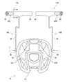
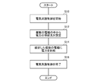
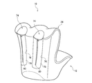
- the electrical stimulator 10 of the present embodiment includes a main body 12, attachments 14L and 14R, and connecting members 16L and 16R.
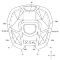
- the main body 12 of the present embodiment is used by being placed on the floor surface FL.
- the description will be made based on the case where the main body 12 is arranged on the horizontal floor surface FL.
- the description will be made using three directions orthogonal to each other.
- This direction is the front-rear direction X, the left-right direction Y, and the up-down direction Z.
- the front-back direction Y and the left-right direction Y are horizontal directions
- the up-down direction Z is a vertical direction.
- the main body 12 is provided with a pair of footrests 18L and 18R that individually correspond to the left and right foot Fts of the user.
- the pair of foot rests 18L and 18R includes a left foot rest 18L corresponding to the left foot and a right foot rest 18R corresponding to the right foot.
- the footrests 18L and 18R have a shape on which at least a part of the corresponding foot Ft can be placed.
- the footrest portions 18L and 18R of the present embodiment are composed of a plurality of footrest regions 20A and 20B.
- the plurality of foot rest areas 20A and 20B include a heel side foot rest area 20A on which at least the heel of the foot Ft can be placed, and a toe side foot rest area 20B on which at least the toes of the foot Ft can be placed.
- the main body 12 is provided with a pair of first electrodes 22L and 22R.
- the pair of first electrodes 22L and 22R are individually provided corresponding to the left and right feet, respectively.
- the pair of first electrodes 22L and 22R of the present embodiment includes a left first electrode 22L corresponding to the left foot and a right first electrode 22R corresponding to the right foot. It can be considered that the pair of first electrodes 22L and 22R correspond to each of the left and right halves of the user.
- the pair of first electrodes 22L and 22R is for applying an electronic stimulus to the corresponding user's foot (half body).
- Each of the pair of first electrodes 22L and 22R of the present embodiment constitutes each of the pair of footrest portions 18L and 18R.
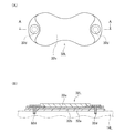
- the main body 12 of the present embodiment has a hollow structure, and includes a housing 24 and a pad member 26 fixed to the housing 24 using screws or the like.
- the pad member 26 of the present embodiment constitutes the footrest portions 18L and 18R and the first electrodes 22L and 22R.
- the pad member 26 is constructed using, for example, conductive rubber.
- This conductive rubber is composed of, for example, a rubber base material such as ethylene propylene diene rubber mixed with a conductivity-imparting agent such as carbon black or metal powder.
- the main body 12 is provided with a plurality of operation units 28A and 28B used for changing the operation of the electrical stimulator 10.
- the plurality of operation units 28A and 28B of the present embodiment include a first operation unit 28A and a second operation unit 28B provided on the upper surface portion of the main body 12.
- the operation units 28A and 28B of the present embodiment are separate members from the housing 24, and are fixed to the housing 24 using screws or the like (not shown).
- the operation units 28A and 28B of the present embodiment constitute buttons that receive a push operation by the user.
- the fixtures 14L and 14R are attached to the user's body.
- the fixtures 14L and 14R of this embodiment are attached to the lower body of the user.
- the "lower body” includes the legs and hips
- the "legs” includes the legs and thighs.
- the attachments 14L and 14R of the present embodiment include a left side attachment 14L corresponding to the left half of the user and a right side attachment 14R corresponding to the right side of the user.
- the left side attachment 14L is attached to the upper thigh of the left leg
- the right side attachment 14R is attached to the upper thigh of the right leg.
- the fixtures 14L and 14R of this embodiment are planar structures having flexibility. Hereinafter, unless otherwise specified, the description will be made based on the state in which the fixtures 14L and 14R are developed in a plane.
- the fixtures 14L and 14R of the present embodiment form a long belt shape when viewed from the thickness direction (direction orthogonal to the paper surface in FIG. 1).
- the attachments 14L and 14R of the present embodiment are attached to the body by wrapping around the body.
- connection structures 30 that are detachably connected to each other are provided at both ends of the fixtures 14L and 14R in the longitudinal direction.
- the connection structure 30 of the present embodiment is a hook-and-loop fastener, but is not particularly limited and may be a snap button or the like.
- the fixtures 14L and 14R of the present embodiment have a hollow structure, and are integrated by sewing the outer edge portion of the front side fabric member 52 and the back side fabric member 54 (see FIG. 8).
- Second electrodes 32L and 32R are provided on the fixtures 14L and 14R.
- the fixtures 14L and 14R are provided with individual second electrodes 32L and 32R corresponding to the plurality of first electrodes 22L and 22R, respectively.
- the plurality of second electrodes 32L and 32R include a left second electrode 32L corresponding to the left first electrode 22L and a right second electrode 32R corresponding to the right first electrode 22R.
- the left side second electrode 32L of the present embodiment is provided on the left side attachment 14L
- the right side second electrode 32R is provided on the right side attachment 14R.
- the plurality of second electrodes 32L and 32R are provided corresponding to the left and right halves, respectively.
- the second electrodes 32L and 32R are for applying electrical stimulation to the half body of the corresponding user.
- the second electrodes 32L and 32R of the present embodiment are applied to the body at the same positions as the attachment positions of the attachments 14L and 14R to the body.
- the left second electrode 32L is applied to the upper thigh of the left leg
- the right second electrode 32R is applied to the upper thigh of the right leg.
- the connecting members 16L and 16R connect the main body 12 and the fixtures 14L and 14R.
- the connecting members 16L and 16R are individually provided corresponding to the plurality of attachments 14L and 14R, respectively, and connect the corresponding attachments 14L and 14R to the main body 12.
- the connection members 16L and 16R correspond to the left side attachment 14L and connect the left side attachment 14L and the main body 12, and the right side attachment 14R and the right side attachment 14R and the main body 12.
- the right side connecting member 16R is included.
- the main body 12 and the attachments 14L and 14R can be integrated by the connecting members 16L and 16R, which makes it easy to carry and use.
- the connecting members 16L and 16R of this embodiment include an electric cable 34. At least a part of the connecting members 16L and 16R has flexibility so as to be able to follow changes in the positions of the main body 12 and the attachments 14L and 14R.
- the "at least a part" here is the electric cable 34 in this embodiment.
- connection members 16L and 16R of the present embodiment can transmit electrical stimulation power from the control unit 48 (described later) mounted on the main body 12 to the second electrodes 32L and 32R of the fixtures 14L and 14R.
- the connecting members 16L and 16R are considered to be capable of transmitting electrical stimulation power supplied from the control unit 48 mounted on one of the main body 12 and the fixtures 14L and 14R to the electrodes provided on the other.
- the "one side” is the main body 12 in the present embodiment
- the “other side” is the fixtures 14 and 14R.
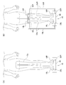
- the connecting members 16L and 16R are detachably connected to at least one of the main body 12 and the attachments 14L and 14R via the first connector 36.
- the connecting members 16L and 16R of the present embodiment are detachably connected to the main body 12, and are connected to the fixtures 14L and 14R by sewing, winding, gluing and the like.
- the first connector 36 is provided at the end of the electric cable 34 of the connecting members 16L and 16R, and the main body 12 is provided with a first receiving portion 38 to which the connecting members 16L and 16R are connected via the first connector 36.
- the first connector 36 is a plug and the first receiving portion 38 is a jack.
- the first receiving portion 38 is provided on the left-right side surface of the main body 12.
- Each block can be realized by an element such as an integrated circuit or a mechanical device in terms of hardware, and by a computer program or the like in terms of software.
- the functional blocks realized by their cooperation are drawn. It is easily understood by those skilled in the art that these functional blocks can be realized in various forms by combining hardware and software.
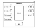
- the power supply 40 in addition to the above-mentioned electrodes 22L, 22R, 32L, 32R and operation units 28A, 28B, the power supply 40, the display unit 42, the contact detection unit 44, and the connection detection unit 46 , And a control unit 48.
- the power supply 40 of this embodiment is housed in the main body 12.
- the power source 40 is a primary battery such as a manganese battery, but may be a rechargeable secondary battery such as a lithium ion battery.
- the power supply 40 is electrically connected to the control unit 48, and supplies electric power to the plurality of electrodes 22L, 22R, 32L, and 32R via the control unit 48.
- the display unit 42 is configured by using, for example, a liquid crystal display, a plasma display, or the like.
- the display unit 42 displays information regarding the operation of the electrical stimulator 10.
- the display unit 42 of the present embodiment displays, for example, the output level of the electric stimulation power.
- the contact detection unit 44 detects the contact state of the user's body with respect to the pair of first electrodes 22L and 22R.
- the contact detection unit 44 is, for example, a load sensor, a touch sensor, a resistance detection circuit, or the like.
- the contact detection unit 44 is electrically connected to the control unit 48, and outputs a signal indicating the detection result to the control unit 48.
- the connection detection unit 46 detects the connection between the main body 12 and the attachments 14L and 14R by the connection members 16L and 16R.
- the connection detection unit 46 is, for example, a resistance detection circuit, a switch, a proximity sensor, or the like.
- the connection detection unit 46 is electrically connected to the control unit 48, and outputs a signal indicating the detection result to the control unit 48.
- the connection detection unit 46 of the present embodiment is individually provided corresponding to the plurality of connection members 16L and 16R, and detects the connection by the corresponding connection members 16L and 16R.
- connection detection unit 46 A case where a resistance detection circuit is used as the connection detection unit 46 will be described.
- the first electrodes 22L and 22R and the second electrodes 32L and 32R are not electrically connected by the connecting members 16L and 16R, and these The electrical resistance between them becomes close to infinity.
- the main body 12 and the fixtures 14L and 14R are connected by the connecting members 16L and 16R
- the first electrodes 22L and 22R and the second electrodes 32L and 32R are electrically connected by the connecting members 16L and 16R.
- the electrical resistance between them is smaller than in the case of.
- connection detection unit 46 When a resistance detection circuit is used for the connection detection unit 46, the resistance values of the first electrodes 22L and 22R and the second electrodes 32L and 32R are detected, and the resistance values and the threshold values are compared to obtain the connection members 16L and 16R. The connection can be detected.
- the control unit 48 of the present embodiment changes the operation of the electrical stimulator 10 in a different manner according to the pressing operation time of the operation units 28A and 28B.
- a pressing operation in which the pressing operation time of the operation units 28A and 28B is less than a predetermined threshold time (for example, 1.5 seconds) is called a short pressing operation, and a pressing operation in which the pressing operation time is longer than the predetermined threshold time is called a long pressing operation.
- the control unit 48 of the present embodiment reduces the output level of the electric stimulation power each time the first operation unit 28A is short-pressed, and increases the output level each time the second operation unit 28B is short-pressed. To do. Further, the control unit 48 of the present embodiment turns off the power supply 40 when the first operation unit 28A is long-pressed, and turns on the power supply 40 when the second operation unit 28B is long-pressed.
- the control unit 48 is electrically connected to a plurality of electrodes 22L, 22R, 32L, 32R and a power supply 40.
- the control unit 48 of the present embodiment is electrically connected to the plurality of first electrodes 22L, 22R and the power supply 40 via the internal wiring of the main body 12, and the internal wiring of the main body 12 is connected to the plurality of second electrodes 32L, 32R. It is electrically connected via the connecting members 16L and 16R.
- the control unit 48 applies electrical stimulation to the user's body by performing electrical stimulation control that controls electrical stimulation power supplied from the power supply 40 to the plurality of electrodes 22L, 22R, 32L, 32R.
- the electric power for electrical stimulation (hereinafter, also simply referred to as electric power) is, for example, an alternating current in a preset frequency range.
- the electric power for electrical stimulation may be, for example, a direct current. This frequency range is set to a range in which the user's muscles can be electrically stimulated.
- the electrical stimulation control is performed by supplying electric power of a predetermined output level to a plurality of electrodes 22L, 22R, 32L, and 32R according to a predetermined operation pattern. When using alternating current, the output level is determined using either the peak value or the effective value of the voltage.
- the control unit 48 sets a power supply destination from a plurality of electrodes 22L, 22R, 32L, and 32R, and supplies power to the set electrodes.
- the control unit 48 of the present embodiment sets a power supply destination from a plurality of electrodes 22L, 22R, 32L, 32R according to the presence or absence of connection between the main body 12 and the connecting members 16L, 16R of the fixtures 14L, 14R. To do. This setting method will be described later.
- the usage scenes of the present embodiment include a first usage scene using a plurality of first electrodes 22L and 22R of the main body 12 (see FIG. 4A), and first electrodes 22L and 22R of the main body 12 and a fixture 14L. , There is a second use scene (see FIG. 4B) using the second electrodes 32L and 32R of 14R.
- the user may take, for example, a standing posture, a sitting posture, or the like.
- the left and right feet are placed on each of the pair of first electrodes 22L and 22R.
- the left and right feet are applied to the pair of first electrodes 22L and 22R, respectively.
- the attachments 14L and 14R are attached to the user's body.
- the second electrodes 32L and 32R of the fixtures 14L and 14R are applied to the user's body.
- the control unit 48 of the electrical stimulator 10 starts the electrical stimulus control when the predetermined electrical stimulus start condition is satisfied (S10).
- the electrical stimulation start condition here is, for example, a long press operation of the second operation unit 28B when the power is on.
- control unit 48 When the control unit 48 starts the electrical stimulation control, the control unit 48 supplies power from the plurality of electrodes 22L, 22R, 32L, 32R depending on whether or not the main body 12 and the attachments 14L, 14R are connected by the connecting members 16L, 16R.
- the control unit 48 of the present embodiment sets the power supply destination based on the detection result of the connection detection unit 46.
- connection detection unit 46 detects the connection of the connection members 16L and 16R of the main bodies 12, 14L and 14R, and the connection detection unit 46 transmits a signal indicating the detection result. Is output to the control unit 48.
- the control unit 48 has a first closed circuit Ca that passes through a plurality of first electrodes 22L and 22R, provided that the main body 12 and the fixtures 14L and 14R are not connected by the connecting members 16L and 16R.
- the power supply destination is set so as to form.
- the control unit 48 of the present embodiment sets the power supply destination in this way on condition that the connection detection unit 46 detects that it is in this state.
- the first closed circuit Ca is a path that passes through at least two first electrodes 22L and 22R of the plurality of first electrodes 22L and 22R and does not pass through the second electrodes 32L and 32R.
- the control unit 48 sets a plurality of first electrodes 22L and 22R forming the first closed circuit Ca as power supply destinations.
- the mode of supplying electric power to the electrodes 22L and 22R set in this way is referred to as a first operation mode.
- the power supply destination is set so as to form the first closed circuit Ca passing through the left first electrode 22L and the right first electrode 22R.
- the left first electrode 22L and the right first electrode 22R are set as the power supply destinations for forming the first closed circuit Ca.
- the first closed circuit Ca serves as a path passing through the control unit 48, the left first electrode 22L, the right first electrode 22R, and the body.
- the "body” here includes the user's left leg, left thigh, hip, right thigh, and right leg in the present embodiment.
- FIG. 4 (B) assume a second usage scene as shown in FIG. 4 (B).
- the main body 12 and the left side mounting tool 14L are connected by the left side connecting member 16L
- the main body 12 and the right side mounting tool 14R are connected by the right side connecting member 16R.
- the control unit 48 passes through the first electrodes 22L and 22R and the second electrodes 32L and 32R, provided that the main body 12 and the fixtures 14L and 14R are connected by the connecting members 16L and 16R in this way.
- the power supply destination is set so as to form the second closed circuits CbL and CbR.
- the control unit 48 of the present embodiment sets the power supply destination in this way on condition that the connection detection unit 46 detects that it is in this state.
- the first electrodes 22L and 22R and the second electrodes 32L and 32R forming the second closed circuits CbL and CbR are provided on the main body 12 and the fixtures 14L and 14R to which the connecting members 16L and 16R are connected, respectively. It is electrically connected via the connecting members 16L and 16R.
- the second closed circuit CbL, CbR passes through the first electrodes 22L, 22R and the second electrodes 32L, 32R, which are electrically connected to each other, and is a different route from the first closed circuit Ca.
- the control unit 48 sets the first electrodes 22L and 22R and the second electrodes 32L and 32R forming the second closed circuits CbL and CbR as power supply destinations.
- the mode of supplying electric power to the electrodes 22L, 22R, 32L, and 32R set in this way is referred to as a second operation mode.
- the control unit 48 of the present embodiment sets the power supply destination so as to form a plurality of second closed circuits CbL and CbR.
- the plurality of second closed circuits CbL and CbR are paths that pass through the first electrodes 22L and 22R and the second electrodes 32L and 32R that are different from each other.
- the plurality of second closed circuits CbL and CbR of the present embodiment are set corresponding to each of the left and right halves of the user.
- the plurality of second closed circuits CbL and CbR include a left second closed circuit CbL corresponding to the left half of the body and a right second closed circuit CbR corresponding to the right half of the body.
- the left second closed circuit CbL passing through the left first electrode 22L and the left second electrode 32L, and the right second closed circuit CbR passing through the right first electrode 22R and the right second electrode 32R are formed.
- the left side first electrode 22L and the left side second electrode 32L are set as the power supply destinations for forming the left side second closed circuit CbL.
- the right side first electrode 22R and the right side second electrode 32R are set as the power supply destinations for forming the right side second closed circuit CbR.
- the left second closed circuit CbL serves as a path passing through the control unit 48, the left first electrode 22L, the left connecting member 16L, the left second electrode 32L, and the body.
- the “body” here includes the user's left foot and left thigh in the present embodiment.
- the right second closed circuit CbR serves as a path passing through the control unit 48, the right first electrode 22R, the right connecting member 16R, the right second electrode 32R, and the body.
- the "body” here includes the user's right foot and right thigh.
- At least one connecting member 16L and 16R is in a state where the main body 12 and the mounting tools 14L and 14R are connected. On condition that, the power supply destination is set in this way.
- the control unit 48 supplies electrical stimulation power to the electrodes 22L, 22R, 32L, and 32R, which are power supply destinations set in S12 (S14).
- the control unit 48 of the present embodiment ends the electrical stimulation control when it finishes supplying the electric stimulation power according to a predetermined operation pattern (S16).
- the electrical stimulator 10 of the present embodiment is attached to the lower body of the user and the second electrode in addition to the main body 12 provided with a pair of first electrodes 22L and 22R individually corresponding to the left and right feet, respectively.
- the fixtures 14L and 14R provided with 32L and 32R are provided. Therefore, in addition to the first closed circuit Ca formed by the pair of first electrodes 22L and 22R, the electric stimulation power is supplied to the second closed circuits CbL and CbR formed by the first electrodes 22L and 22R and the second electrodes 32L and 32R. Can be supplied.
- the intensity of electrical stimulation to the user's muscles tends to weaken as the energization path in the body becomes longer.
- the second electrodes 32L and 32R of the present embodiment are provided corresponding to the pair of first electrodes 22L and 22R, respectively. Therefore, the left second closed circuit CbL for the left half of the body can be formed by the left first electrode 22L corresponding to the left foot and the left second electrode 32L corresponding thereto. In addition to this, the right second closed circuit CbR for the right half of the body can be formed by the right first electrode 22R corresponding to the right foot and the corresponding right second electrode 32R. Therefore, when power is supplied to the second closed circuit CbL and CbR, the intensity of electrical stimulation to the muscles on both the second closed circuit CbL and CbR is higher than that when power is supplied to the first closed circuit Ca. It can be increased, and the sensation can be improved by electrical stimulation.
- the control unit 48 is mounted on a main body 12 placed on the floor surface FL, and the main body 12 and the fixtures 14L and 14R are connected by connecting members 16L and 16R. Therefore, even if the control unit 48 is not mounted on the fixtures 14L and 14R, the electric stimulation power can be supplied to the second electrodes 32L and 32R of the fixtures 14L and 14R via the connecting members 16L and 16R. Therefore, the weight of the fixtures 14L and 14R can be reduced, and the user can easily move even if the fixtures 14L and 14R are attached.
- the control unit 48 sets a power supply destination from a plurality of electrodes 22L, 22R, 32L, 32R according to the presence or absence of connection by the connection members 16L, 16R of the main bodies 12, 14L, 14R. Power is supplied to the set electrodes 22L, 22R, 32L, 32R. Therefore, in order to change the power supply destination from the plurality of electrodes 22L, 22R, 32L, and 32R, it is possible to eliminate the need to operate the operation units 28A and 28B of the main body 12, and good usability can be obtained.
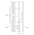
- FIGS. 7 and 8 Most of the configurations of the left side second electrode 32L and the left side attachment 14L and the configuration of the right side second electrode 32R and the right side attachment 14R are common. Here, this common configuration will be described with reference to FIGS. 7 and 8 showing the former.
- the second electrodes 32L and 32R are provided on the back surface of the fixtures 14L and 14R.
- the second electrodes 32L and 32R of the present embodiment constitute an electrode pad that is applied to the skin surface of the body.
- the second electrodes 32L and 32R form a sheet as a whole.
- the second electrodes 32L and 32R have a base material 32a, a conductive portion 32b, an adhesive portion 32c, and a fixing portion 32d.
- the base material 32a has a sheet shape formed of, for example, a resin such as PET.
- the conductive portion 32b is configured by using a conductive material such as silver paste.
- the conductive portion 32b is provided on the side opposite to the fixtures 14L and 14R with respect to the base material 32a.
- the adhesive portion 32c is provided on the side opposite to the fixtures 14L and 14R with respect to the conductive portion 32b. Adhesive portions 32c will be provided on the back surfaces of the fixtures 14L and 14R. The adhesive portion 32c is detachably attached to the body. The fixtures 14L and 14R will be attached to the body via the adhesive portion 32c.
- the adhesive portion 32c of the present embodiment has conductivity, and is conducted to the conductive portion 32b by a conductive adhesive or the like. When the adhesive portion 32c of the second electrodes 32L and 32R is attached to the body, the conductive portion 32b and the skin surface of the body are conductive via the adhesive portion 32c.
- the adhesive portion 32c of the present embodiment is composed of an adhesive gel. As a result, the second electrodes 32L and 32R are less likely to be displaced with respect to the skin surface.
- the fixtures 14L and 14R have a fixed portion 50 to which the fixing portion 32d of the second electrodes 32L and 32R is detachably fixed.
- the fixed portion 32d and the fixed portion 50 of the present embodiment form a snap button in which a male snap and a female snap are combined.
- the fixed portion 50 is integrated with the fixtures 14L and 14R by sewing or the like.
- the second electrodes 32L and 32R are electrically connected to the control unit 48 via connecting members 16L and 16R connected to the fixed portion 50 of the fixtures 14L and 14R.
- the leg muscles are easy to move greatly by electrical stimulation, and also easy to move greatly by swinging the ankle.
- the attachments 14L and 14R are only attached to the body via the adhesive portion 32c, there is a high risk that the adhesive portion 32c will be peeled off from the body due to the movement of the muscles of the legs.
- the second electrodes 32L and 32R of the present embodiment are provided on the belt-shaped attachments 14L and 14R. Therefore, by wrapping the attachments 14L and 14R around the body, it becomes easy to avoid the situation where the adhesive portion 32c is peeled off from the body. Along with this, it becomes easier to maintain the state in which the second electrodes 32L and 32R are in contact with the body, and the conductive state of the second electrodes 32L and 32R with respect to the body can be stabilized.
- the belt-shaped attachments 14L and 14R have elasticity in the longitudinal direction. This may be realized by forming the attachments 14L and 14R with a stretchable material, or by providing the attachments 14L and 14R with an expansion and contraction portion such as a bellows structure. As a result, the fixtures 14L and 14R expand and contract in accordance with the movement of the leg muscles, so that it becomes easier to maintain the state in which the second electrodes 32L and 32R are in contact with the body.
- the back side fabric member 54 of the fixtures 14L and 14R is made of an airtight material.
- This material is, for example, a polyurethane film, chloroprene rubber, or the like.
- sweat generated from the body tends to be trapped on the back side of the fixtures 14L and 14R.
- the skin surface becomes easily moisturized at the portion where the second electrodes 32L and 32R hit the body, and the conduction state of the second electrodes 32L and 32R to the body becomes good.
- the back side fabric member 54 of the fixtures 14L and 14R may be configured to have higher elasticity than the front side fabric member 52.
- the back side fabric member 54 may be configured to have a larger elongation rate [%] than the front side fabric member 52.
- the elongation rate here means the ratio of the deformed dimension to the original dimension in that direction when a predetermined load is applied in the direction in which the elongation is most likely to occur.
- the knitting method of the fabrics constituting the front side fabric member 52 and the back side fabric member 54 and the Young's modulus of the fabric material may be changed.
- the back side fabric member 54 is larger than the case where the elasticity of the back side fabric member 54 is the same as that of the front side fabric member 52. While deforming, the deformation of the front side fabric member 52 can be suppressed. Along with this, changes in design and occurrence of wrinkles due to deformation of the front side fabric member 52 can be suppressed, and it becomes easy to avoid a situation in which the user feels uncomfortable due to the occurrence. Further, by suppressing the change in the appearance of the front side fabric member 52, it becomes easy to grasp the movement of the muscles of the body in the vicinity thereof, and it becomes easy to grasp how the body is moving due to the electrical stimulation.
- the electrical stimulator 10 of the second embodiment includes a heater 60.
- the heater 60 of this embodiment is mounted on the main body 12.
- the heater 60 is, for example, a sheathed heater, a cartridge heater, or the like.
- the heater 60 of the present embodiment is arranged at a position where the contact point of the user's body on the main body 12 can be heated when an electric stimulus is applied to the muscle of the user.
- the "contact points" are the electrodes 22L and 22R of the main body 12.
- the "contact points" are the footrests 18L and 18R of the main body 12 in the present embodiment.
- the heater 60 of the present embodiment is arranged inside the main body 12 on the back side of the footrest portions 18L and 18R (first electrodes 22L and 22R).
- a part of the body in contact with the main body 12 can be warmed by the heater 60, and the blood flow of the body can be promoted at the warmed part.
- it becomes easy to dilate the blood vessels of the body at the warmed part and it becomes easy to suppress the electric resistance when the electric current flows through the blood vessels.
- the heater 60 may be mounted on the fixtures 14L and 14R. In this case as well, the heater 60 may heat the contact points of the user's body on the fixtures 14L and 14R when applying electrical stimulation to the user's muscles.
- the electrical stimulator 10 of the third embodiment includes light sources 62L and 62R mounted on the main body 12. Although the light sources 62L and 62R of this embodiment are mounted on the main body 12, they may be mounted on the fixtures 14L and 14R. The light sources 62L and 62R have a role of notifying the operation of the electrical stimulator 10.
- the light sources 62L and 62R are, for example, LEDs, discharge lamps, incandescent bulbs, and the like.
- the light sources 62L and 62R of the present embodiment are provided at a position where the lighting state can be visually recognized on the upper surface portion of the main body 12.
- the housing 24 of the main body 12 is provided with peripheral portions 64L and 64R on the peripheral edges of the first electrodes 22L and 22R (foot rest portions 18L and 18R).
- the peripheral edge portions 64L and 64R include a left peripheral edge portion 64L provided on the peripheral edge of the left side first electrode 22L and a right peripheral edge portion 64R provided on the peripheral edge of the right side first electrode 22R.
- the light sources 62L and 62R of the present embodiment include a left light source 62L corresponding to the left first electrode 22L and a right light source 62R corresponding to the right first electrode 22R.
- the left light source 62L is provided on the left peripheral edge 64L of the main body 12, and the right light source 62R is provided on the right peripheral edge 64R of the main body 12.
- the light sources 62L and 62R are provided so as to be located on a line along the peripheral portions 64L and 64R of the main body 12.
- the individual light sources 62L and 62R are continuously provided on the line, but may be provided discretely on the line at intervals.
- the control unit 48 controls the lighting state of the light sources 62L and 62R in conjunction with the supply of electrical stimulation power to the first electrodes 22L and 22R of the main body 12. Specifically, when power is being supplied to the first electrodes 22L and 22R, the light sources 62L and 62R corresponding to the first electrodes 22L and 22R are turned on. When power is being supplied to the left first electrode 22L, the left light source 62L corresponding to the left first electrode 22L is turned on. When power is being supplied to the right first electrode 22R, the right light source 62R corresponding to the right first electrode 22R is turned on. In order to light the light sources 62L and 62R in this way, the light sources 62L and 62R may be continuously turned on, or the light sources 62L and 62R may be blinked.
- the control unit 48 may control the lighting state of the light sources 62L and 62R in conjunction with the output level of the electric stimulation power. For example, consider the case of using light sources 62L and 62R whose amount of light can be changed. In this case, the control unit 48 may increase the amount of light of the light sources 62L and 62R as the output level increases, and decrease the amount of light of the light sources 62L and 62R as the output level decreases.
- control unit 48 may bring the wavelengths of the light sources 62L and 62R closer to one end side of the wavelength region as the output level increases, and may bring the wavelengths of the light sources 62L and 62R closer to the other end side of the wavelength region as the output level decreases. ..
- control unit 48 brings the blinking speeds of the light sources 62L and 62R closer to one end side (for example, the slowing side) of the variable range as the output level increases, and the other end side (for example) of the variable range as they decrease. , The side to speed up) may be approached.
- control unit 48 may control the light sources 62L and 62R in the same manner as the output level in conjunction with the frequency of the electric stimulation power as an alternative to the output level.
- the electrical stimulator 10 of the fourth embodiment has different configurations of the fixtures 14L and 14R as compared with the first embodiment.
- the attachments 14L and 14R of the present embodiment are footwear 66 that can be attached by being worn on the user's foot.
- socks are shown as an example of the footwear 66.
- the footwear 66 constituting the right side attachment 14R is shown, but the left side attachment 14L is also composed of the footwear 66.
- the footwear 66 of the present embodiment includes a bottom portion 66a that covers the entire sole of the user, an instep covering portion 66b that covers the instep of the user, a heel covering portion 66c that covers the user's heel from both the left and right sides and the rear side, and the user's footwear 66.
- a thigh cover portion 66d that covers the thigh is provided.
- a conductive portion 66e is provided on the bottom portion 66a of the footwear 66.
- hatching is provided at a portion that becomes the conductive portion 66e.
- the conductive portion 66e is configured by using a conductive material such as a conductive fiber.
- the user's foot Ft is conducted with respect to the first electrodes 22L and 22R via the conductive portion 66e of the footwear 66.
- a portion different from the bottom 66a of the footwear 66 constitutes an insulating portion 66f.
- the insulating portion 66f is configured by using an insulating material such as an insulating fiber.
- the insulating portion 66f of the present embodiment is composed of the instep covering portion 66b, the heel covering portion 66c, and the thigh covering portion 66d of the attachments 14L and 14R.
- the second electrodes 32L and 32R of the present embodiment are provided inside the thigh covering portion 66d of the footwear 66.
- the second electrodes 32L and 32R will be provided at a location different from the bottom 66a of the footwear 66. It can be said that the second electrodes 32L and 32R are provided inside the insulating portion 66f of the footwear 66.
- the second electrodes 32L and 32R of the present embodiment form an annular shape so as to come into contact with the thighs of the body over the entire circumference. It can be said that the second electrodes 32L and 32R have a shape of contacting the thigh of the body over a range of more than half a circumference. This facilitates the formation of a closed circuit that passes through the thighs of the body in a wide range below the contact positions of the second electrodes 32L and 32R with respect to the body.
- the connecting members 16L and 16R are detachably connected to the footwear 66 via the second connector 68.
- the second connector 68 is provided at the end of the electric cable 34 of the connecting members 16L and 16R, and the footwear 66 is provided with a second receiving portion 70 to which the connecting members 16L and 16R are connected via the second connector 68.
- the second connector 68 is a male snap and the second receiving portion 70 is a female snap, which constitute a snap button.
- the second receiving portion 70 is integrated with the footwear 66 by sewing or the like.
- the second electrodes 32L and 32R are electrically connected to the control unit 48 (not shown) via the second receiving portion 70 of the footwear 66 and the connecting members 16L and 16R.
- the user can use the electric stimulator 10 without being barefoot, and the trouble of taking off the footwear 66 can be eliminated. Further, depending on the usage environment of the electric stimulator 10, the user may be restricted from being barefoot, and even in such a case, the user can use the electric stimulator 10.
- the above footwear 66 is preferably made of a highly airtight and flexible material such as polyurethane.
- a highly airtight and flexible material such as polyurethane.
- the heat retention and moisture retention of the footwear 66 are enhanced, the moisture content of the skin is increased at the place where the footwear 66 (socks) is worn, and the electric resistance at the place where the footwear 66 is worn can be suppressed.
- the intensity of the electrical stimulation to the muscles of the portion where the footwear 66 is worn can be increased, and the sensation of the electrical stimulation can be improved.
- the shapes of the second electrodes 32L and 32R are not particularly limited when they are provided on the thigh covering portion 66d of the footwear 66.
- the second electrodes 32L and 32R may be in contact with the thighs of the body within a range of less than half a circumference.
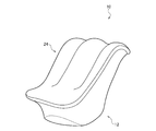
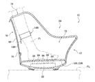
- the electrical stimulator 10 of the present embodiment mainly differs in the configuration of the main body 12.
- the main body 12 includes a housing 24 that forms a storage space 72 that accommodates the user's left and right feet.
- the housing 24 is made of a hard synthetic resin or the like.
- the accommodation space 72 of the present embodiment can accommodate a part of the thigh in addition to the user's foot.
- the pair of first electrodes 22L and 22R described above form an accommodation space 72 of the main body 12. The same applies to the pair of footrests 18L and 18R described above.
- a pair of insertion ports 74 for inserting the user's feet are formed on the upper surface portion on the rear side of the housing 24.
- a continuous opening 76 is formed in each of the pair of insertion ports 74 on the rear surface portion of the housing 24.
- the main body 12 includes a cover body 78 that covers the opening 76 of the housing 24.
- the cover body 78 is made of a synthetic resin or fiber softer than the housing 24.
- the cover body 78 is provided with an opening / closing tool 80 such as a wire fastener capable of opening / closing the cover body 78.
- the electrical stimulator 10 of the present embodiment further includes a germicidal lamp 82 that irradiates the accommodation space 72 with germicidal light.
- the sterilizing light is light in a wavelength range having a sterilizing effect such as ultraviolet rays.
- the germicidal lamp 82 of the present embodiment is arranged on the back side of the footrests 18L and 18R of the main body 12 and inside the main body 12.
- the footrests 18L and 18R of the main body 12 of the present embodiment are provided with a translucent portion 84 capable of transmitting sterilizing light.
- the translucent portion 84 of the present embodiment is a through hole penetrating the footrest portions 18L and 18R.
- the translucent portion 84 may be made of a translucent material capable of transmitting sterilizing light.
- the germicidal lamp 82 can suppress the growth of bacteria caused by the sweat, and good hygiene can be obtained.
- the sterilizing light is irradiated into the accommodation space 72 of the main body 12, the sterilizing light is less likely to leak to the outside of the main body 12. Along with this, it is possible to avoid the situation where the sterilizing light is seen with the naked eye, and the burden on the user's eyes can be suppressed. Further, since the germicidal light does not easily leak to the outside of the main body 12, there is an advantage that the output of the germicidal lamp 82 can be easily increased.
- the germicidal lamp 82 may be arranged at a position where the germicidal light can be applied to a part of the body other than the soles of the feet placed on the footrests 18L and 18R.
- This part of the body means a part accommodated in the accommodation space 72 of the main body 12.
- This part of the body includes, for example, the instep and heel of the foot other than the sole of the foot, as well as the lower leg and the like.
- the germicidal lamp 82 may be arranged at a position where the germicidal lamp 82 can be irradiated to the entire accommodation space 72. In this case, the sterilizing light is applied to the entire exposed portion of the body part of the accommodation space 72 that is accommodated in the accommodation space 72. In any case, the germicidal lamp 82 can irradiate the feet accommodated in the accommodation space 72 with germicidal light.
- the control unit 48 of the electrical stimulator 10 may control the germicidal lamp 82 so as to irradiate the germicidal lamp in conjunction with the supply of the electrical stimulation power to the plurality of electrodes 22L, 22R, 32L, 32R.
- the sterilizing light may be irradiated during the supply of the electric stimulation electric power, or the sterilizing light may be irradiated for a predetermined time after the supply of the electric stimulation electric power is completed.
- the fixtures 14L and 14R of the present embodiment are attached to the user's body in the accommodation space 72 of the main body 12.
- the "user's body” here is the lower leg of the user in the present embodiment.
- the connecting members 16L and 16R of the present embodiment are arranged so as to pass only the inside of the main body 12 without passing through the outside. As the inside of the main body 12, it is arranged so as to pass through at least the accommodation space 72 of the main body 12. As a result, the fixtures 14L and 14R and the connecting members 16L and 16R are not exposed to the outside of the main body 12, and the electrical stimulator 10 having a neat appearance can be realized.
- the electrical stimulator 10 of the present embodiment is different from the fifth embodiment in that the fixtures 14L and 14R and the connecting members 16L and 16R.
- the attachments 14L and 14R of the present embodiment are attached to the user's body outside the accommodation space 72 of the main body 12.
- the "user's body” here is the user's upper thigh in the present embodiment.
- the connecting members 16L and 16R of the present embodiment are arranged outside the main body 12.
- the positions of the fixtures 14L and 14R and the connecting members 16L and 16R are not particularly limited.
- the electrical stimulator 10 of the present embodiment is different from the fifth embodiment in that it includes a blower 86.
- the blower unit 86 includes a heat exchanger 88 that changes the temperature of the air taken in from the outside of the main body 12, and a fan 90 that supplies the air whose temperature has been changed by the heat exchanger 88 into the accommodation space 72.
- the heat exchanger 88 of the present embodiment can heat the outside air, and the fan 90 supplies the heated air into the accommodation space 72.
- the amount of water in the skin of a part of the body increases at the place where it is housed, and the electrical resistance at that place can be suppressed.
- the intensity of the electrical stimulation to the muscles of the portion housed in the storage space 72 can be increased, and the sensation of the electrical stimulation can be improved.
- the heat exchanger 88 may be able to cool the outside air.
- the fan 90 supplies the cooled air into the accommodation space 72.
- the blower portion 86 may be configured not to include the heat exchanger 88.
- the user can feel the coolness by blowing the wind on the feet in the accommodation space 72 of the main body 12, and the electric stimulator 10 can be easily used in a high temperature environment.
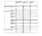
- the operation indicated by "Status” is to repeat the operation of a predetermined cycle by the "number of cycles" of the line to which each "Status” belongs.
- This "predetermined cycle” is an operation in which the operations of the plurality of lines to which the "Status” belongs are performed in order from the top line.
- This "operation of multiple lines” is an operation of supplying alternating current to a plurality of electrodes 22L, 22R, 32L, 32R for the "required time” of the same line at the "frequency” of the referred line. Is.
- the operation indicated by "Interval” is an operation of stopping the supply of alternating current to the plurality of electrodes 22L, 22R, 32L, and 32R for the "required time” of the row to which each "Interval” in FIG. 17 belongs.
- FIG. 17 mainly shows an operation pattern in which the following alternating currents (1), (2), and (3) are combined.
- (1) is an alternating current suitable for loosening muscles.
- (2) is an alternating current suitable for strength training.
- (3) is an alternating current suitable for imparting a physical sensation due to electrical stimulation.
- FIG. 17 shows an operation mode for strength training in which the alternating current of (2) is combined.
- (1) Alternating current in a predetermined frequency band (less than 15 Hz) suitable for promoting simple contraction in muscles (2)
- FIG. 18 is an operation pattern in which the above-mentioned (1) and (3) are combined.
- FIG. 18 shows an operation mode for healthcare that mainly uses the alternating current of (1) without using the alternating current of (2).
- the fixtures 14L and 14R may be attached to the lower body of the user.
- the attachments 14L and 14R may be attached to the waist in addition to the user's thighs.
- the attachments 14L and 14R are attached to the upper thighs of both legs in the examples of FIGS. 4 (B) and 19 (described later).
- the attachments 14L and 14R may be attached to either the shins or ankles of both legs, that is, the lower legs of both legs.
- the main body 12 may be attached to the user. That is, the main body 12 may be placed on the floor surface or may be attached to the user.
- the fixtures 14L and 14R may be attached to a place other than the lower body of the user, that is, the upper body.
- the number of fixtures 14L and 14R is not particularly limited.
- the fixtures 14L and 14R may be singular or three or more.
- the mounting mode of the main body 12 and the fixtures 14L and 14R on the body is not particularly limited. This mounting mode is, for example, winding, hooking, pasting, or the like.
- the shapes of the main body 12 and the fixtures 14L and 14R are not particularly limited. For example, it may be a planar structure having a shape that can be attached only to the front surface or the rear surface of the user.
- first electrodes 22L and 22R may be provided as the plurality of first electrodes 22L and 22R.
- the first electrodes 22L and 22R may be provided separately from the footrest portions 18L and 18R.
- a pad covering the instep may be provided on the main body 12 above the foot rests 18L and 18R, and the first electrodes 22L and 22R may be provided on the pad.
- a pad for covering the heel of the foot from the rear side may be provided behind the foot rests 18L and 18R, and the first electrodes 22L and 22R may be provided on the pad.
- the number of the second electrodes 32L and 32R provided on the fixtures 14L and 14R is not limited, and only a single second electrode 32L and 32R may be provided, or three or more second electrodes 32L and 32R may be provided. May be done.
- the plurality of second electrodes 32L, 32R corresponding to the plurality of first electrodes 22L, 22R may be provided on a single fixture 14L, 14R, or may be provided on individual fixtures 14L, 14R.
- the adhesive portion 32c of the fixtures 14L and 14R may be provided at a location different from the second electrodes 32L and 32R.
- it may be provided on the back surface of the fixtures 14L and 14R at a location other than the second electrodes 32L and 32R.
- the first electrodes 22L and 22R are provided on the main body 12.
- the connecting members 16L and 16R are detachably connected to the main body 12
- they may be detachably connected to the fixtures 14L and 14R, or may be detachably connected to both main bodies 12, 14L and 14R. May be.
- a member different from the electric cable 34 may be provided.
- This "another member” is, for example, a controller on which the control unit 48 is mounted.
- the connecting members 16L and 16R may include an electric cable for connecting the controller and the main body 12, an electric cable for connecting the controller and the fixtures 14L and 14R, and a controller.
- the plurality of connecting members 16L and 16R corresponding to the plurality of attachments 14L and 14R may be connected to the main body 12 via a single first connector 36.
- the power supply 40 may be housed in the fittings 14L and 14R, or may be provided outside the main body 12 and the fittings 14L and 14R.
- the power source 40 may be configured by an external power source such as a commercial power source provided separately from the electrical stimulator 10.
- the control unit 48 may be mounted on the fixtures 14L and 14R, or may be mounted on a member different from the main body 12 and the fixtures 14L and 14R.
- the control unit 48 may be able to independently change the output level of the electric stimulation power for each of the plurality of closed circuits.
- the left side second closed circuit CbL and the right side second closed circuit CbR may be changed independently.
- the electrical stimulator 10 may include an operation unit for switching the closed circuit to which the output level is changed.
- the electrical stimulator 10 causes another control unit that switches the power supply 40 from off to on, triggered by the contact detection unit 44 detecting that the user's body has come into contact with the pair of first electrodes 22L and 22R. You may have it.
- an auxiliary power source different from the above-mentioned power source 40 may be mounted on the main body 12, and the contact detection unit 44 and other control units may operate based on the auxiliary power source.
- the electrical stimulator 10 may include a notification unit that notifies the operation of the electrical stimulator 10 by sound.
- This notification unit is, for example, a speaker or the like.
- the notification unit may notify that the electrical stimulation device 10 has started the electrical stimulation control or has finished the electrical stimulation control. In addition to this, it may be notified that an input has been received to the operation units 28A and 28B of the electric stimulator 10.
- the operation on the electrical stimulator 10 may be performed through the operation on the remote controller.
- the remote controller may be dedicated to the electrical stimulator 10 or may be a general-purpose information processing terminal incorporating an application capable of operating the electrical stimulator 10.
- the electric stimulator 10 may include a conductive material arranged separately from the electrodes between the electrodes and the body.
- the conductive material is, for example, a conductive fiber, a conductive rubber, or the like.
- the attachments 14L, and 14R of the electric stimulator 10 are attached to the body, they do not have to be directly attached to the user's body.
- the innerwear is worn on the body, the innerwear is partially provided with a conductive material at the place where the electrodes of the main body 12, the fixtures 14L and 14R hit, and the main body 12 and the fixtures 14L are placed on the innerwear. , 14R may be attached. This allows you to train without taking off your innerwear.
- the second electrodes 32L and 32R By changing the positions of the second electrodes 32L and 32R that come into contact with the body, it is possible to change the sensation when electrical stimulation is applied.
- strong electrical stimulation can be applied to the quadriceps femoris.
- strong electrical stimulation can be applied to the muscles in the range from the shin to the foot on the premise that the first electrodes 22L and 22R of the main body 12 are applied to the foot.
- a strong electrical stimulation can be applied to the hamstring.
- strong electrical stimulation can be applied to the muscles in the range from the calf to the foot on the premise that the first electrodes 22L and 22R of the main body 12 are applied to the foot.
- strong electrical stimulation can be applied to the calf muscle
- the second electrodes 32L and 32R are applied to the shin of the lower leg, strong electrical stimulation can be applied to the shin muscle.
- FIG. 19 shows a third use scene of the electrical stimulator 10 of the first embodiment.
- the first electrodes 22L and 22R of the main body 12 are not used, but the second electrodes 32L and 32R of the fixtures 14L and 14R are used.
- the attachments 14L and 14R are attached to the user's body as in the second usage scene.
- the second electrodes 32L and 32R of the fixtures 14L and 14R are applied to the user's body.
- the main body 12 and the fixtures 14L and 14R are connected by the connecting members 16L and 16R.
- a third closed circuit Cc passing through the plurality of second electrodes 32L and 32R is formed.
- the third closed circuit Cc is a path that does not pass through the plurality of first electrodes 22L and 22R and passes through the control unit 48, the left second electrode 32L, the right second electrode 32R, and the body.
- the "body” here includes the left thigh, the waist, and the right thigh in the present embodiment.
- the control unit 48 may set the power supply destination as follows. In both the second usage scene (see FIG. 4B) and the third usage scene, the main body 12 and the fixtures 14L and 14R are in a state of being connected by the connecting members 16L and 16R. On condition that it is in this state, the control unit 48 sets the power supply destination so as to form any of the second closed circuit CbL, CbR, and the third closed circuit Cc in S12.
- the electrode to be supplied with electric power may be selected by the user through an operation on an operation unit (for example, operation units 28A and 28B) of the electrical stimulator 10. At this time, the user selects an electrode to be a power supply destination from the electrodes corresponding to any of the second closed circuit CbL, CbR and the third closed circuit Cc.
- the electrode to which the electric power is supplied may be selected by the user in advance before starting the electrical stimulation control.
- the control unit 48 may request an electrode to be selected by the user after starting the electrical stimulation control.
- the first electrodes 22L and 22R and the second electrodes 32L and 32R are set as power supply destinations as the electrodes corresponding to the second closed circuits CbL and CbR.
- the second electrodes 32L and 32R are set as power supply destinations as the electrodes corresponding to the third closed circuit Cc.
- any combination of the above components is also effective as an aspect of the present invention.
- any explanatory matter of the modified example may be combined with the embodiment, or arbitrary explanatory matter of the embodiment and other modified examples may be combined with the modified example. An example of this combination will be described.
- the heater 60 of the second embodiment, the light sources 62L and 62R of the third embodiment, the socks of the fourth embodiment, the germicidal lamp 82 of the fifth embodiment, and the blower 86 of the seventh embodiment are electrics of other embodiments. It may be combined with the stimulator 10. Further, the electrical stimulator 10 of the fifth and seventh embodiments may be used as if the fixtures 14L and 14R and the second electrodes 32L and 32R are omitted.
- the main body 12 includes a housing 24 that forms an accommodation space 72.
- the heater 60 may be arranged at a position where the accommodation space 72 of the main body 12 can be heated. Even in this case, a part of the body in the accommodation space 72 can be heated by the heater 60, and the blood flow of the body can be promoted at the heated portion.
- the intensity of the electrical stimulation to the muscles around the warmed part can be easily increased, and the sensation of the electrical stimulation can be improved.
- the heater 60 may be arranged at a position where the main body 12 can heat the accommodation space 72.
- the second electrodes 32L and 32R of the fixtures 14L and 14R can also be heated by the heater 60. If the second electrodes 32L and 32R, whose temperature is lower than that of the body, come into contact with the body for a long period of time, the user may feel uncomfortable due to a feeling of coldness. In this respect, according to such a configuration, the temperature difference from the body can be reduced by warming the second electrodes 32L and 32R, and it becomes easy to avoid a situation in which the user is uncomfortable due to a feeling of coldness.
- An electrical stimulator that applies electrical stimulation to a user's muscles, the main body, a plurality of first electrodes provided on the main body, an attachment attached to the user's body, and the attachment.
- the second electrode provided, the control unit that controls the electric stimulation power supplied from the power source to the plurality of first electrodes and the second electrode, the main body and the fixture are connected, and the power is transmitted.
- a connecting member is provided, the connecting member is detachably connected to at least one of the main body and the fitting, and the control unit is connected to the main body and the fitting by the connecting member.
- An electrical stimulator that sets a power supply destination from the plurality of first electrodes and the second electrode accordingly, and supplies the power to the set electrodes.
- the inventor of the present application has obtained the recognition that there is room for improvement in terms of usability in applying electrical stimulation using electrodes of a plurality of main bodies.
- the present invention relates to an electrical stimulator.
- 10 Electrical stimulator, 12 ... Main body, 14L, 14R ... Fixture, 16L, 14R ... Connection member, 22L, 22R ... First electrode, 32L, 32R ... Second electrode, 40 ... Power supply, 46 ... Connection detector, 48 ... Control unit.
Landscapes
- Health & Medical Sciences (AREA)
- Engineering & Computer Science (AREA)
- Biomedical Technology (AREA)
- Nuclear Medicine, Radiotherapy & Molecular Imaging (AREA)
- Radiology & Medical Imaging (AREA)
- Life Sciences & Earth Sciences (AREA)
- Animal Behavior & Ethology (AREA)
- General Health & Medical Sciences (AREA)
- Public Health (AREA)
- Veterinary Medicine (AREA)
- Electrotherapy Devices (AREA)
Abstract
電気刺激による体感の向上を図れる電気刺激装置を提供する。ユーザの筋肉に電気刺激を付与する電気刺激装置であって、本体12と、ユーザの左右の足のそれぞれに対応して個別に本体12に設けられる一対の第1電極22L、22Rと、ユーザの下半身に取り付けられる取付具14L、14Rと、取付具14L、14Rに設けられる第2電極32L、32Rと、一対の第1電極22L、22R及び第2電極32L、32Rに電源から供給される電気刺激用電力を制御する制御部48と、を備える。
Description
本発明は、電気刺激装置に関する。
従来、ユーザの筋肉に電気刺激を付与する電気刺激装置が提案されている。これを用いることで、筋肉の収縮と弛緩を伴う運動が促される。この一例として、特許文献1には、左右の足に対応する一対の足用電極が本体に設けられた電気刺激装置が記載される。
本発明者は、特許文献1の電気刺激装置を検討した。この結果、一対の足用電極が設けられる本体を用いて電気刺激を付与する場合に、電気刺激による体感の向上を図るうえで改良の余地があるとの認識を得た。
本発明のある態様は、このような課題に鑑みてなされ、その目的の1つは、電気刺激による体感の向上を図れる電気刺激装置を提供することにある。
前述の課題を解決するための本発明のある態様は、ユーザの筋肉に電気刺激を付与する電気刺激装置であって、本体と、ユーザの左右の足のそれぞれに対応して個別に前記本体に設けられ、その対応する足に当てられる一対の第1電極と、ユーザの下半身に取り付けられる取付具と、前記取付具に設けられる第2電極と、前記一対の第1電極及び前記第2電極に電源から供給される電気刺激用電力を制御する制御部と、を備える。
前述の電気刺激装置によれば、電気刺激による体感の向上を図れる。
以下、本発明の実施形態の一例を説明する。同一の構成要素には同一の符号を付し、重複する説明を省略する。各図面では、説明の便宜のため、構成要素の一部を適宜省略したり、その寸法を適宜拡大、縮小する。図面は符号の向きに合わせて見るものとする。本明細書での「当てる」、「接触」、「固定」、「取り付け」とは、特に明示がない限り、言及している条件を二者が直接的に満たす場合の他に、他の部材を介して満たす場合も含む。
(第1の実施の形態)
図1を参照する。電気刺激装置10は、ユーザの筋肉に電気刺激を付与するためのものである。本明細書での「ユーザ」とは、たとえば、電気刺激装置10が販売される国で平均体格を持つものをいう。電気刺激装置10は、たとえば、筋力トレーニングに利用できる。本実施形態の電気刺激装置10は、本体12と、取付具14L、14Rと、接続部材16L、16Rとを備える。
図1を参照する。電気刺激装置10は、ユーザの筋肉に電気刺激を付与するためのものである。本明細書での「ユーザ」とは、たとえば、電気刺激装置10が販売される国で平均体格を持つものをいう。電気刺激装置10は、たとえば、筋力トレーニングに利用できる。本実施形態の電気刺激装置10は、本体12と、取付具14L、14Rと、接続部材16L、16Rとを備える。
図2、図3を参照する。本実施形態の本体12は床面FLに置かれて用いられる。以下、特に明示しない限り、本体12を水平な床面FL上に配置したときを基準に説明する。このとき、互いに直交する三つの方向を用いて説明する。この方向とは、前後方向X、左右方向Y及び上下方向Zである。前後方向Y、左右方向Yは水平方向であり、上下方向Zは鉛直方向である。
本体12には、ユーザの左右の足Ftのそれぞれに個別に対応する一対の足置き部18L、18Rが設けられる。一対の足置き部18L、18Rには、左足に対応する左足置き部18Lと、右足に対応する右足置き部18Rとが含まれる。
足置き部18L、18Rは、対応する足Ftの少なくとも一部を置くことができる形状である。本実施形態の足置き部18L、18Rは、複数の足置き領域20A、20Bにより構成される。複数の足置き領域20A、20Bには、足Ftの少なくとも踵を置くことができる踵側足置き領域20Aと、足Ftの少なくともつま先を置くことができるつま先側足置き領域20Bとが含まれる。
本体12には、一対の第1電極22L、22Rが設けられる。一対の第1電極22L、22Rは、左右の足のそれぞれに対応して個別に設けられる。本実施形態の一対の第1電極22L、22Rには、左足に対応する左側第1電極22Lと、右足に対応する右側第1電極22Rとが含まれる。一対の第1電極22L、22Rは、ユーザの左右の半身のそれぞれに対応しているとも捉えられる。一対の第1電極22L、22Rは、対応するユーザの足(半身)に当てて電子刺激を付与するためのものである。本実施形態の一対の第1電極22L、22Rのそれぞれは、一対の足置き部18L、18Rのそれぞれを構成する。
本実施形態の本体12は中空構造であり、ハウジング24と、ビス等を用いてハウジング24に固定されるパッド部材26とを備える。本実施形態のパッド部材26は足置き部18L、18Rや第1電極22L、22Rを構成する。パッド部材26は、たとえば、導電性ゴムを用いて構成される。この導電性ゴムは、たとえば、エチレンプロピレンジエンゴム等のゴム基材に、カーボンブラック、金属粉末等の導電性付与剤を混ぜ込んで構成される。
本体12には、電気刺激装置10の動作の変更に用いられる複数の操作部28A、28Bが設けられる。本実施形態の複数の操作部28A、28Bには、本体12の上面部に設けられる第1操作部28A及び第2操作部28Bが含まれる。本実施形態の操作部28A、28Bは、ハウジング24とは別部材であり、不図示のビス等を用いてハウジング24に固定される。本実施形態の操作部28A、28Bはユーザによる押し操作を受けるボタンを構成する。
図1、図4(B)を参照する。取付具14L、14Rは、ユーザの身体に取り付けられる。本実施形態の取付具14L、14Rは、ユーザの下半身に取り付けられる。ここでの「下半身」には脚、腰が含まれ、「脚」には足、腿が含まれる。本実施形態の取付具14L、14Rには、ユーザの左半身に対応する左側取付具14Lと、その右半身に対応する右側取付具14Rとが含まれる。本実施形態において、左側取付具14Lは左脚の上腿に取り付けられ、右側取付具14Rは右脚の上腿に取り付けられる。
本実施形態の取付具14L、14Rは、可とう性を持つ面状構造体である。以下、特に言及しない限り、取付具14L、14Rを平面的に展開した状態を基準に説明する。本実施形態の取付具14L、14Rは、その厚み方向(図1の紙面直交方向)から見て長尺なベルト状をなす。本実施形態の取付具14L、14Rは、身体への巻き付けにより、身体に取り付けられる。
取付具14L、14Rの長手方向の両端部には互いに着脱可能に接続する接続構造30が設けられる。本実施形態の接続構造30は、面ファスナーであるが、特に限定されず、スナップボタン等でもよい。本実施形態の取付具14L、14Rは中空構造であり、表側生地部材52と裏側生地部材54(図8参照)の外縁部の縫い付けにより一体化される。
取付具14L、14Rには第2電極32L、32Rが設けられる。取付具14L、14Rには、複数の第1電極22L、22Rのそれぞれに対応する個別の第2電極32L、32Rが設けられる。複数の第2電極32L、32Rには、左側第1電極22Lに対応する左側第2電極32Lと、右側第1電極22Rに対応する右側第2電極32Rとが含まれる。本実施形態の左側第2電極32Lは左側取付具14Lに設けられ、右側第2電極32Rは右側取付具14Rに設けられる。複数の第2電極32L、32Rは、一対の第1電極22L、22Rと同様、左右の半身のそれぞれに対応して設けられる。第2電極32L、32Rは、対応するユーザの半身に当てて電気刺激を付与するためのものである。本実施形態の第2電極32L、32Rは、身体に対する取付具14L、14Rの取り付け位置と同様の箇所で身体に当てられる。本実施形態において、左側第2電極32Lは左脚の上腿に当てられ、右側第2電極32Rは右脚の上腿に当てられる。
接続部材16L、16Rは、本体12と取付具14L、14Rを接続する。接続部材16L、16Rは、複数の取付具14L、14Rのそれぞれに対応して個別に設けられ、その対応する取付具14L、14Rと本体12を接続する。接続部材16L、16Rには、左側取付具14Lに対応するとともに左側取付具14Lと本体12を接続する左側接続部材16Lと、右側取付具14Rに対応するとともに右側取付具14Rと本体12を接続する右側接続部材16Rが含まれる。これにより、本体12と取付具14L、14Rを接続部材16L、16Rにより一体化でき、その持ち運びや取り使いが容易となる。
本実施形態の接続部材16L、16Rは、電気ケーブル34を備える。接続部材16L、16Rの少なくとも一部は、本体12や取付具14L、14Rの位置の変化に追従できるように可とう性を持つ。ここでの「少なくとも一部」は、本実施形態では電気ケーブル34である。
本実施形態の接続部材16L、16Rは、本体12に搭載される制御部48(後述する)から取付具14L、14Rの第2電極32L、32Rに電気刺激用電力を伝送可能である。接続部材16L、16Rは、本体12及び取付具14L、14Rのうちの一方に搭載される制御部48から、他方に設けられる電極に供給される電気刺激用電力を伝送可能であると捉えられる。ここでの「一方」とは、本実施形態では本体12であり、「他方」とは、取付具14、14Rである。
接続部材16L、16Rは、本体12及び取付具14L、14Rのうちの少なくとも一方の本体に第1コネクタ36を介して着脱可能に繋げられる。本実施形態の接続部材16L、16Rは、本体12に着脱可能に繋げられ、取付具14L、14Rには、縫い付け、巻き付け、接着等により繋げられる。第1コネクタ36は接続部材16L、16Rの電気ケーブル34の端部に設けられ、本体12には接続部材16L、16Rが第1コネクタ36を介して繋がる第1受け部38が設けられる。本実施形態において、第1コネクタ36はプラグであり、第1受け部38はジャックである。本実施形態において、第1受け部38は本体12の左右方向の側面に設けられる。
図5を参照する。各ブロックは、ハードウェア的には、集積回路をはじめとする素子や機械装置で実現でき、ソフトウェア的にはコンピュータプログラム等によって実現される。ここでは、それらの連携によって実現される機能ブロックを描いている。これらの機能ブロックはハードウェア、ソフトウェアの組み合わせによっていろいろなかたちで実現できることは当業者に容易に理解される。
本実施形態の電気刺激装置10は、前述の電極22L、22R、32L、32Rや操作部28A、28Bの他に、電源40と、表示部42と、接触検知部44と、接続検知部46と、制御部48と、を備える。
本実施形態の電源40は、本体12に収納される。電源40は、マンガン電池等の一次電池であるが、リチウムイオン電池等の充電可能な二次電池でもよい。電源40は、制御部48に電気的に接続され、複数の電極22L、22R、32L、32Rに制御部48を介して電力を供給する。
表示部42は、たとえば、液晶ディスプレイ、プラズマディスプレイ等を用いて構成される。表示部42は、電気刺激装置10の動作に関する情報を表示する。本実施形態の表示部42は、たとえば、電気刺激用電力の出力レベルを表示する。
接触検知部44は、一対の第1電極22L、22Rに対するユーザの身体の接触状態を検知する。接触検知部44は、たとえば、荷重センサ、タッチセンサ、抵抗検出回路等である。接触検知部44は、制御部48に電気的に接続され、その検知結果を示す信号を制御部48に出力する。
接続検知部46は、本体12と取付具14L、14Rの接続部材16L、16Rによる接続を検知する。接続検知部46は、たとえば、抵抗検出回路、スイッチ、近接センサ等である。接続検知部46は、制御部48に電気的に接続され、その検知結果を示す信号を制御部48に出力する。本実施形態の接続検知部46は、複数の接続部材16L、16Rに対応して個別に設けられ、その対応する接続部材16L、16Rによる接続を検知する。
接続検知部46として抵抗検出回路を用いる場合を説明する。本体12と取付具14L、14Rが接続部材16L、16Rにより接続されていない場合、接続部材16L、16Rにより第1電極22L、22Rと第2電極32L、32Rが電気的に接続されず、これらの間の電気抵抗が無限大に近くなる。一方、本体12と取付具14L、14Rが接続部材16L、16Rにより接続されている場合、接続部材16L、16Rにより第1電極22L、22Rと第2電極32L、32Rが電気的に接続され、前述の場合より、これらの間の電気抵抗が小さくなる。接続検知部46に抵抗検出回路を用いる場合、これら第1電極22L、22Rと第2電極32L、32Rの抵抗値を検出し、その抵抗値と閾値を比較することで、接続部材16L、16Rによる接続を検知できる。
本実施形態の制御部48は、操作部28A、28Bの押し操作時間に応じて、電気刺激装置10の動作を異なる態様で変更する。操作部28A、28Bの押し操作時間が所定の閾値時間(たとえば、1.5秒)未満の押し操作を短押し操作といい、所定の閾値時間以上の押し操作を長押し操作という。本実施形態の制御部48は、第1操作部28Aが短押し操作される毎に電気刺激用電力の出力レベルを小さくし、第2操作部28Bが短押し操作される毎に出力レベルを大きくする。また、本実施形態の制御部48は、第1操作部28Aが長押し操作されると電源40をオフにし、第2操作部28Bが長押し操作されると電源40をオンにする。
制御部48は、複数の電極22L、22R、32L、32Rや電源40に電気的に接続される。本実施形態の制御部48は、複数の第1電極22L、22Rや電源40に本体12の内部配線を介して電気的に接続され、複数の第2電極32L、32Rに本体12の内部配線や接続部材16L、16Rを介して電気的に接続される。
制御部48は、電源40から複数の電極22L、22R、32L、32Rに供給される電気刺激用電力を制御する電気刺激制御を行うことで、ユーザの身体に電気刺激を付与する。この電気刺激用電力(以下、単に電力ともいう)は、たとえば、予め設定された周波数範囲の交流電流である。この電気刺激用電力は、この他にも、たとえば、直流電流でもよい。この周波数範囲は、ユーザの筋肉に電気刺激を与えることができる範囲に設定される。電気刺激制御は、予め定められた動作パターンに従って、予め定められた出力レベルの電力を複数の電極22L、22R、32L、32Rに供給することで行われる。出力レベルは、交流電流を用いる場合、その電圧のピーク値または実効値のいずれかを用いて定められる。
この電気刺激制御では、制御部48は、複数の電極22L、22R、32L、32Rの中から電力の供給先を設定し、その設定した電極に電力を供給する。本実施形態の制御部48は、本体12と取付具14L、14Rの接続部材16L、16Rによる接続の有無に応じて、複数の電極22L、22R、32L、32Rの中から電力の供給先を設定する。この設定方法は後述する。
以上の電気刺激装置10の利用シーンの一例を説明する。図4を参照する。本実施形態の利用シーンには、本体12の複数の第1電極22L、22Rを用いた第1利用シーン(図4(A)参照)と、本体12の第1電極22L、22Rや取付具14L、14Rの第2電極32L、32Rを用いた第2利用シーン(図4(B)参照)とがある。いずれの利用シーンでも、ユーザは、たとえば、立位姿勢、座位姿勢等をとってもよい。
第1利用シーンでは、一対の第1電極22L、22Rのそれぞれに左右の足を当てる。本実施形態では、一対の第1電極22L、22Rが構成する足置き部18L、18Rに足を載せることで、一対の第1電極22L、22Rのそれぞれに左右の足を当てる。第2利用シーンでは、第1利用シーンでの本体12の使い方に加えて、ユーザの身体に取付具14L、14Rを取り付ける。これにより、取付具14L、14Rの第2電極32L、32Rがユーザの身体に当てられる。
次に、電気刺激装置10の動作の一例を説明する。図4、図6を参照する。
電気刺激装置10の制御部48は、予め定められた電気刺激開始条件を満たしたときに電気刺激制御を開始する(S10)。ここでの電気刺激開始条件とは、たとえば、電源がオンの状態にあるときに第2操作部28Bを長押し操作することである。
制御部48は、電気刺激制御を開始すると、本体12と取付具14L、14Rの接続部材16L、16Rによる接続の有無に応じて、複数の電極22L、22R、32L、32Rの中から電力の供給先を設定する(S12)。本実施形態の制御部48は、接続検知部46の検知結果に基づいて、電力の供給先を設定する。
詳しくは、制御部48は、電気刺激制御を開始すると、各本体12、14L、14Rの接続部材16L、16Rによる接続を接続検知部46により検知させ、その検知結果を示す信号を接続検知部46から制御部48に出力させる。
図4(A)に示すような第1利用シーンを想定する。図の例では、本体12と取付具14L、14Rが接続部材16L、16Rにより接続されていない状態にある。制御部48は、このように本体12と取付具14L、14Rが接続部材16L、16Rにより接続されていない状態にあることを条件として、複数の第1電極22L、22Rを通る第1閉回路Caを形成するように電力の供給先を設定する。本実施形態の制御部48は、この状態にあると接続検知部46が検知したことを条件として、このように電力の供給先を設定する。
第1閉回路Caは、複数の第1電極22L、22Rのうちの少なくとも二つの第1電極22L、22Rを通り、かつ、第2電極32L、32Rを通らない経路である。このとき、制御部48は、第1閉回路Caを形成する複数の第1電極22L、22Rを電力の供給先として設定する。以下、このように設定された電極22L、22Rに電力を供給するモードを第1動作モードという。
図の例でいうと、左側第1電極22Lと右側第1電極22Rを通る第1閉回路Caを形成するように電力の供給先を設定する。このとき、第1閉回路Caを形成する電力の供給先として、左側第1電極22Lと右側第1電極22Rを設定する。この第1閉回路Caは、制御部48、左側第1電極22L、右側第1電極22R及び身体を通る経路となる。ここでの「身体」には、本実施形態では、ユーザの左足、左腿、腰、右腿、右足が含まれる。この第1閉回路Caに電気刺激用電力を供給すると、その経路上にある筋肉の運動が促される。
次に、図4(B)に示すような第2利用シーンを想定する。図の例では、本体12と左側取付具14Lが左側接続部材16Lにより接続され、本体12と右側取付具14Rが右側接続部材16Rにより接続されている状態にある。制御部48は、このように本体12と取付具14L、14Rが接続部材16L、16Rにより接続されている状態にあることを条件として、第1電極22L、22Rと第2電極32L、32Rを通る第2閉回路CbL、CbRを形成するように電力の供給先を設定する。本実施形態の制御部48は、この状態にあると接続検知部46が検知したことを条件として、このように電力の供給先を設定する。
第2閉回路CbL、CbRを形成する第1電極22L、22Rと第2電極32L、32Rは、接続部材16L、16Rが接続している本体12と取付具14L、14Rのそれぞれに設けられ、その接続部材16L、16Rを介して電気的に接続されている。第2閉回路CbL、CbRは、互いに電気的に接続されている第1電極22L、22Rと第2電極32L、32Rを通り、かつ、第1閉回路Caとは異なる経路である。このとき、制御部48は、第2閉回路CbL、CbRを形成する第1電極22L、22Rと第2電極32L、32Rを電力の供給先として設定する。以下、このように設定された電極22L、22R、32L、32Rに電力を供給するモードを第2動作モードという。
本実施形態の制御部48は、複数の第2閉回路CbL、CbRを形成するように電力の供給先を設定する。この複数の第2閉回路CbL、CbRは、互いに異なる第1電極22L、22R及び第2電極32L、32Rを通る経路である。本実施形態の複数の第2閉回路CbL、CbRはユーザの左右の半身のそれぞれに対応して設定される。複数の第2閉回路CbL、CbRには、左半身に対応する左側第2閉回路CbLと、右半身に対応する右側第2閉回路CbRとが含まれる。
図の例でいうと、左側第1電極22Lと左側第2電極32Lを通る左側第2閉回路CbLと、右側第1電極22Rと右側第2電極32Rを通る右側第2閉回路CbRを形成するように電力の供給先を設定する。このとき、左側第2閉回路CbLを形成する電力の供給先として、左側第1電極22Lと左側第2電極32Lを設定する。また、右側第2閉回路CbRを形成する電力の供給先として、右側第1電極22Rと右側第2電極32Rを設定する。左側第2閉回路CbLは、制御部48、左側第1電極22L、左側接続部材16L、左側第2電極32L及び身体を通る経路となる。ここでの「身体」には、本実施形態では、ユーザの左足、左腿が含まれる。右側第2閉回路CbRは、制御部48、右側第1電極22R、右側接続部材16R、右側第2電極32R及び身体を通る経路となる。ここでの「身体」には、ユーザの右足、右腿が含まれる。各第2閉回路CbL、CbRに電気刺激用電力を供給すると、その経路上にある筋肉の運動が促される。
本実施形態のように複数の取付具14L、14Rに対応する複数の接続部材16L、16Rがある場合、少なくとも一つの接続部材16L、16Rが本体12と取付具14L、14Rを接続した状態にあることを条件として、このように電力の供給先を設定する。
制御部48は、S12において設定した電力の供給先となる電極22L、22R、32L、32Rに電気刺激用電力を供給する(S14)。本実施形態の制御部48は、予め定められた動作パターンに従って電気刺激用電力を供給し終えると、電気刺激制御を終了する(S16)。
以上の電気刺激装置10の効果を説明する。
(A1)本実施形態の電気刺激装置10は、左右の足のそれぞれに個別に対応する一対の第1電極22L、22Rが設けられる本体12の他に、ユーザの下半身に取り付けられるとともに第2電極32L、32Rが設けられた取付具14L、14Rを備える。よって、一対の第1電極22L、22Rが形成する第1閉回路Caの他に、第1電極22L、22Rと第2電極32L、32Rが形成する第2閉回路CbL、CbRに電気刺激用電力を供給できる。ユーザの筋肉に対する電気刺激の強度は身体における通電経路が長くなるほど弱くなる傾向がある。第2閉回路CbL、CbRに電力を供給する場合、第1閉回路Caに電力を供給する場合と比べ、その通電経路上に左右の両脚を通さずともすむため、その通電経路の長さを短くし易くなる(図4参照)。よって、第2閉回路CbL、CbRに電力を供給する場合、第1閉回路Caに電力を供給する場合と比べ、その第2閉回路CbL、CbR上の筋肉に対する電気刺激の強度を増大でき、電気刺激による体感の向上を図れる。
(A2)本実施形態の第2電極32L、32Rは、一対の第1電極22L、22Rのそれぞれに対応して設けられる。よって、左足に対応する左側第1電極22Lと、それに対応する左側第2電極32Lとにより左半身用の左側第2閉回路CbLを形成できる。また、この他にも、右足に対応する右側第1電極22Rと、それに対応する右側第2電極32Rとにより右半身用の右側第2閉回路CbRを形成できる。このため、第2閉回路CbL、CbRに電力を供給する場合、第1閉回路Caに電力を供給する場合と比べ、第2閉回路CbL、CbRの両方の上の筋肉に対する電気刺激の強度を増大でき、電気刺激による体感の向上を図れる。
(A3)制御部48は、床面FLに置かれる本体12に搭載され、その本体12と取付具14L、14Rは接続部材16L、16Rにより接続される。よって、取付具14L、14Rに制御部48を搭載せずとも、接続部材16L、16Rを介して電気刺激用電力を取付具14L、14Rの第2電極32L、32Rに供給できる。このため、取付具14L、14Rの重量の軽量化を図れ、取付具14L、14Rを取り付けてもユーザが動き易くなる。
(B)制御部48は、各本体12、14L、14Rの接続部材16L、16Rによる接続の有無に応じて、複数の電極22L、22R、32L、32Rの中から電力の供給先を設定し、その設定した電極22L、22R、32L、32Rに電力を供給する。よって、複数の電極22L、22R、32L、32Rの中から電力の供給先を変えるうえで、本体12の操作部28A、28Bに対する操作を不要にでき、良好な使い勝手を得られる。
次に、電気刺激装置10の他の特徴を説明する。
図7、図8を参照する。左側第2電極32Lと左側取付具14Lの構成と、右側第2電極32Rと右側取付具14Rの構成は、その大半が共通である。ここでは、この共通する構成に関して、前者を示す図7、図8を用いて説明する。
第2電極32L、32Rは、取付具14L、14Rの裏面部に設けられる。本実施形態の第2電極32L、32Rは、身体の肌面に当てられる電極パッドを構成する。第2電極32L、32Rは、全体としてシート状をなす。
第2電極32L、32Rは、基材32aと、導電部32bと、粘着部32cと、固定部32dと、を有する。基材32aは、たとえば、PET等の樹脂を用いて構成されるシート状をなす。導電部32bは、たとえば、銀ペースト等の導電材を用いて構成される。導電部32bは、基材32aに対して取付具14L、14Rとは反対側に設けられる。
粘着部32cは、導電部32bに対して取付具14L、14Rとは反対側に設けられる。取付具14L、14Rの裏面部に粘着部32cが設けられることになる。粘着部32cは、身体に着脱可能に貼り付けられる。取付具14L、14Rは粘着部32cを介して身体に取り付けられることになる。本実施形態の粘着部32cは導電性を有し、導電性接着剤等により導電部32bに導通される。第2電極32L、32Rの粘着部32cを身体に貼り付けたとき、その粘着部32cを介して導電部32bと身体の肌面が導通される。本実施形態の粘着部32cは粘着性ゲルが構成する。これにより、第2電極32L、32Rが肌面に対して位置ずれし難くなる。
取付具14L、14Rは、第2電極32L、32Rの固定部32dが着脱可能に固定される被固定部50を有する。本実施形態の固定部32dと被固定部50は雄スナップと雌スナップを組み合わせたスナップボタンを構成する。被固定部50は、縫い付け等により取付具14L、14Rに一体化される。第2電極32L、32Rは、取付具14L、14Rの被固定部50に接続される接続部材16L、16R等を介して制御部48に電気的に接続される。
脚の筋肉は電気刺激により大きく動き易いうえ、足首の揺動によっても大きく動き易い。これらが相まって、取付具14L、14Rを粘着部32cを介して身体に取り付けるのみでは、その脚の筋肉の動きにより身体から粘着部32cが剥がれるリスクが大きい。この点、本実施形態の第2電極32L、32Rは、ベルト状の取付具14L、14Rに設けられている。よって、取付具14L、14Rを身体に巻き付けることで、身体から粘着部32cが剥がれる事態を避け易くなる。これに伴い、第2電極32L、32Rが身体に対して接触した状態を維持し易くなり、第2電極32L、32Rの身体に対する導通状態を安定化できる。
ベルト状の取付具14L、14Rは長手方向に伸縮性を持つと好ましい。これは、取付具14L、14Rを伸縮性を持つ素材により構成することで実現してもよいし、取付具14L、14Rに蛇腹構造等の伸縮部を設けることで実現してもよい。これにより、脚の筋肉の動きに追従して取付具14L、14Rが伸縮することで、第2電極32L、32Rが身体に対して接触した状態を更に維持し易くなる。
取付具14L、14Rの裏側生地部材54は気密性を持つ素材により構成すると好ましい。この素材は、たとえば、ポリウレタンフィルム、クロロプレンゴム等である。これにより、取付具14L、14Rの裏側に身体から発した汗がこもり易くなる。これに伴い、第2電極32L、32Rの身体に当たる箇所で肌面が潤い易くなり、その第2電極32L、32Rの身体に対する導通状態が良好となる。
取付具14L、14Rの裏側生地部材54は表側生地部材52より伸縮性が高くなるように構成されてもよい。これを実現するうえで、裏側生地部材54は表側生地部材52より伸び率[%]が大きくなるように構成されてもよい。ここでの伸び率とは、最も伸び易い方向に所定の荷重を付与した場合において、その方向での元の寸法に対する変形後の寸法の割合をいう。表側生地部材52や裏側生地部材54の伸縮性を調整するうえでは、たとえば、表側生地部材52や裏側生地部材54を構成する生地の編み方や生地の素材のヤング率を変更してもよい。
これにより、取付具14L、14Rが身体の筋肉の動きに追従して伸縮しようとしたとき、裏側生地部材54の伸縮性を表側生地部材52と同じにする場合と比べ、裏側生地部材54が大きく変形する一方で表側生地部材52の変形を抑えられる。これに伴い、表側生地部材52の変形に伴うデザインの変化や皺等の発生を抑えられ、その発生に起因してユーザが不快を感じる事態を避け易くなる。また、表側生地部材52の外観の変化を抑えることで、その近傍での身体の筋肉の動きを把握し易くなり、電気刺激により身体が動いている様子を把握し易くなる。
(第2の実施の形態)
図9を参照する。第1実施形態の電気刺激装置10の発明特定事項のうち、以下の図で示していない事項は、以降の実施形態において第1実施形態と同じ内容が適用される。
図9を参照する。第1実施形態の電気刺激装置10の発明特定事項のうち、以下の図で示していない事項は、以降の実施形態において第1実施形態と同じ内容が適用される。
第2実施形態の電気刺激装置10は、ヒーター60を備える。本実施形態のヒーター60は本体12に搭載される。ヒーター60は、たとえば、シーズヒータ、カートリッジヒータ等である。本実施形態のヒーター60は、ユーザの筋肉に電気刺激を付与するときに、本体12におけるユーザの身体の接触箇所を加熱可能な位置に配置される。この「接触箇所」とは、本実施形態では、本体12の電極22L、22Rである。別の捉え方をすると、この「接触箇所」とは、本実施形態では、本体12の足置き部18L、18Rである。このような位置として、本実施形態のヒーター60は、本体12の内部にて足置き部18L、18R(第1電極22L、22R)の裏側に配置される。
これにより、本体12に接触している身体の一部をヒーター60により温めることができ、その温めた箇所で身体の血流を促進できる。これに伴い、その温めた箇所で身体の血管を拡張し易くなり、その血管を通して電流が流れる際の電気抵抗を抑え易くなる。この結果、その温めた箇所の周囲の筋肉に対する電気刺激の強度を増大し易くなり、電気刺激による体感の向上を図れる。
なお、ヒーター60は、取付具14L、14Rに搭載されてもよい。この場合も、ヒーター60は、ユーザの筋肉に電気刺激を付与するときに、取付具14L、14Rにおけるユーザの身体の接触箇所を加熱してもよい。
(第3の実施の形態)
図10を参照する。第3実施形態の電気刺激装置10は、本体12に搭載される光源62L、62Rを備える。本実施形態の光源62L、62Rは本体12に搭載されるが取付具14L、14Rに搭載されてもよい。光源62L、62Rは、電気刺激装置10の動作を報知する役割を持つ。光源62L、62Rは、たとえば、LED、放電灯、白熱球等である。本実施形態の光源62L、62Rは、本体12の上面部にて点灯状態を視認可能な位置に設けられる。
図10を参照する。第3実施形態の電気刺激装置10は、本体12に搭載される光源62L、62Rを備える。本実施形態の光源62L、62Rは本体12に搭載されるが取付具14L、14Rに搭載されてもよい。光源62L、62Rは、電気刺激装置10の動作を報知する役割を持つ。光源62L、62Rは、たとえば、LED、放電灯、白熱球等である。本実施形態の光源62L、62Rは、本体12の上面部にて点灯状態を視認可能な位置に設けられる。
本体12のハウジング24には、第1電極22L、22R(足置き部18L、18R)の周縁に周縁部64L、64Rが設けられる。周縁部64L、64Rには、左側第1電極22Lの周縁に設けられる左側周縁部64Lと、右側第1電極22Rの周縁に設けられる右側周縁部64Rとが含まれる。本実施形態の光源62L、62Rは、左側第1電極22Lに対応する左側光源62Lと、右側第1電極22Rに対応する右側光源62Rとが含まれる。左側光源62Lは、本体12の左側周縁部64Lに設けられ、右側光源62Rは、本体12の右側周縁部64Rに設けられる。
光源62L、62Rは本体12の周縁部64L、64Rに沿ったライン上に位置するように設けられる。これを実現するうえで、本実施形態では、個々の光源62L、62Rはライン上に連続的に設けられているが、そのライン上に間隔を空けて離散的に設けられてもよい。
制御部48(図示せず)は、本体12の第1電極22L、22Rに対する電気刺激用電力の供給と連動して光源62L、62Rの点灯状態を制御する。詳しくは、第1電極22L、22Rに電力を供給しているとき、その第1電極22L、22Rに対応する光源62L、62Rを点灯させる。左側第1電極22Lに電力を供給しているとき、左側第1電極22Lに対応する左側光源62Lを点灯させる。右側第1電極22Rに電力を供給しているとき、右側第1電極22Rに対応する右側光源62Rを点灯させる。このように光源62L、62Rを点灯させるうえで、光源62L、62Rを継続的に点灯してもよいし、光源62L、62Rを点滅させてもよい。
これにより、光源62L、62Rの点灯を視認することで、電気刺激装置10の動作状況として、複数の電極22L、22R、32L、32Rに電気刺激用電力が供給されていることを把握できる。
制御部48は、電気刺激用電力の出力レベルと連動して光源62L、62Rの点灯状態を制御してもよい。たとえば、光量を変更可能な光源62L、62Rを用いる場合を考える。この場合、制御部48は、出力レベルが大きくなるほど光源62L、62Rの光量を大きくし、それが小さくなるほど光源62L、62Rの光量を小さくしてもよい。
この他にも、可視域での波長を変更可能な光源62L、62Rを用いる場合を考える。この場合、制御部48は、出力レベルが大きくなるほど光源62L、62Rの波長を波長領域の一端側に近づけ、それが小さくなるほど光源62L、62Rの波長を波長領域の他端側に近づけてもよい。
この他にも、制御部48は、出力レベルが大きくなるほど光源62L、62Rの点滅速度を可変範囲の一端側(たとえば、遅くする側)に近づけ、それらが小さくなるほど可変範囲の他端側(たとえば、速くする側)に近づけてもよい。
これにより、光源62L、62Rの点灯状態を視認することで、電気刺激装置10の動作状況として、電気刺激装置10により付与される電気刺激の強さを把握できる。
なお、制御部48は、出力レベルの代替として、電気刺激用電力の周波数に連動して、出力レベルと同様に光源62L、62Rを制御してもよい。
(第4の実施の形態)
図11を参照する。第4実施形態の電気刺激装置10は、第1実施形態と比べ、取付具14L、14Rの構成が相違する。詳しくは、本実施形態の取付具14L、14Rはユーザの足に履くことで取り付けられる履き物66である。本実施形態では、この履き物66の一例として靴下を示す。本図では右側取付具14Rを構成する履き物66のみ示すが、左側取付具14Lも履き物66が構成する。
図11を参照する。第4実施形態の電気刺激装置10は、第1実施形態と比べ、取付具14L、14Rの構成が相違する。詳しくは、本実施形態の取付具14L、14Rはユーザの足に履くことで取り付けられる履き物66である。本実施形態では、この履き物66の一例として靴下を示す。本図では右側取付具14Rを構成する履き物66のみ示すが、左側取付具14Lも履き物66が構成する。
本実施形態の履き物66は、ユーザの足裏の全体を覆う底部66aと、ユーザの甲を覆う甲覆い部66bと、ユーザの踵を左右両側かつ後側から覆う踵覆い部66cと、ユーザの腿を覆う腿覆い部66dとを備える。
履き物66の底部66aには導電部66eが設けられる。図11では導電部66eとなる箇所にハッチングを付す。導電部66eは、導電性繊維等の導電性素材を用いて構成される。ユーザの足Ftは、第1電極22L、22Rに対して履き物66の導電部66eを介して導通される。
履き物66の底部66aとは異なる箇所は絶縁部66fを構成する。絶縁部66fは、絶縁性繊維等の絶縁性素材を用いて構成される。本実施形態の絶縁部66fは、取付具14L、14Rの甲覆い部66b、踵覆い部66c、腿覆い部66dが構成する。
本実施形態の第2電極32L、32Rは、履き物66の腿覆い部66dの内部に設けられる。第2電極32L、32Rは、履き物66の底部66aとは異なる箇所に設けられることになる。第2電極32L、32Rは、履き物66の絶縁部66fの内部に設けられるともいえる。本実施形態の第2電極32L、32Rは、身体の腿に全周に亘る範囲で接触するよう環状をなしている。第2電極32L、32Rは、身体の腿に半周以上に亘る範囲で接触する形状であるともいえる。これにより、第2電極32L、32Rの身体に対する接触位置より下方において身体の腿を広範囲で通る閉回路を形成し易くなる。
接続部材16L、16Rは、履き物66に第2コネクタ68を介して着脱可能に繋がれる。第2コネクタ68は、接続部材16L、16Rの電気ケーブル34の端部に設けられ、履き物66には、接続部材16L、16Rが第2コネクタ68を介して繋がる第2受け部70が設けられる。本実施形態において第2コネクタ68は雄スナップであり、第2受け部70は雌スナップであり、これらはスナップボタンを構成する。第2受け部70は、縫い付け等により履き物66に一体化される。第2電極32L、32Rは、履き物66の第2受け部70や接続部材16L、16Rを介して制御部48(図示せず)に電気的に接続される。
以上の電気刺激装置10によっても、前述の(A1)~(A3)、(B)の効果を得られる。
(C)また、この他にも、裸足にならずに電気刺激装置10をユーザが利用でき、履き物66を脱ぐ手間を不要にできる。また、電気刺激装置10の使用環境によってはユーザが裸足になることが制限される場合があるが、そのような場合でも電気刺激装置10をユーザが利用できる。
以上の履き物66は、ポリウレタン等の密閉性が高く、柔軟性のある素材により構成されると好ましい。これにより、履き物66の保温性や保湿性が高まり、履き物66(靴下)を着けている箇所で肌の水分量が増し、その着けている箇所での電気抵抗を抑えられる。これに伴い、履き物66を着けている箇所の筋肉に対する電気刺激の強度を増大でき、電気刺激による体感の向上を図れる。
なお、第2電極32L、32Rは、履き物66の腿覆い部66dに設ける場合、その形状は特に限られない。たとえば、第2電極32L、32Rは、身体の腿に半周未満の範囲で接触する形状でもよい。
(第5の実施の形態)
図12、図13、図14を参照する。本実施形態の電気刺激装置10は、主に、本体12の構成が相違する。本体12は、ユーザの左右の足を収容する収容空間72を形成するハウジング24を備える。ハウジング24は、硬質な合成樹脂等を素材に構成される。本実施形態の収容空間72は、ユーザの足の他に腿の一部を収容可能である。前述の一対の第1電極22L、22Rは、本体12の収容空間72を形成している。前述の一対の足置き部18L、18Rも同様である。
図12、図13、図14を参照する。本実施形態の電気刺激装置10は、主に、本体12の構成が相違する。本体12は、ユーザの左右の足を収容する収容空間72を形成するハウジング24を備える。ハウジング24は、硬質な合成樹脂等を素材に構成される。本実施形態の収容空間72は、ユーザの足の他に腿の一部を収容可能である。前述の一対の第1電極22L、22Rは、本体12の収容空間72を形成している。前述の一対の足置き部18L、18Rも同様である。
ハウジング24の後側の上面部にはユーザの足を差し込むための一対の差込口74が形成される。ハウジング24の後面部には一対の差込口74のそれぞれに連続する開口76が形成される。本体12は、ハウジング24の開口76を覆うカバー体78を備える。カバー体78は、ハウジング24より軟質な合成樹脂や繊維を用いて構成される。カバー体78にはカバー体78を開閉可能な線ファスナー等の開閉具80が設けられる。開閉具80によりカバー体78を開いた状態にすることで、本体12の収容空間72内に足を入れやすくなる。本体12の収容空間72内に足を入れた後は開閉具80によりカバー体78を閉じた状態にすることで、収容空間72と外部空間の間での空気の流れを遮り易くなる。
本実施形態の電気刺激装置10は、更に、収容空間72内に殺菌光を照射する殺菌灯82を備える。殺菌光は、紫外線等の殺菌効果を持つ波長域の光である。本実施形態の殺菌灯82は、本体12の足置き部18L、18Rの裏側かつ本体12の内部に配置される。本実施形態の本体12の足置き部18L、18Rには殺菌光を透過可能な透光部84が設けられる。本実施形態の透光部84は足置き部18L、18Rを貫通する貫通孔である。透光部84は、この他にも、殺菌光を透過可能な透光性を持つ素材により構成されてもよい。これにより、足置き部18L、18Rに置かれた足Ftの足裏に殺菌光を照射可能となる。
これにより、電気刺激装置10を用いたトレーニングにより足に汗をかいたとしても、その汗に起因する菌の繁殖を殺菌灯82により抑制でき、良好な衛生性を得られる。また、ユーザにとっては衛生面を大きく気にせず安心して使える利点がある。
また、本体12の収容空間72内に殺菌光が照射されるため、その殺菌光が本体12の外部に漏れ難くなる。これに伴い、殺菌光を肉眼で見る事態を避けることができ、ユーザの目への負担を抑えられる。また、本体12の外部に殺菌光が漏れ難いため、殺菌灯82の出力を大きくし易い利点もある。
殺菌灯82は、足置き部18L、18Rに置かれた足の足裏以外の身体の一部に殺菌光を照射可能な位置に配置されてもよい。この身体の一部とは、本体12の収容空間72に収容される箇所をいう。この身体の一部とは、たとえば、足の足裏以外の箇所である足の甲やかかとの他、下腿等が含まれる。
また、殺菌灯82は、収容空間72内の全体に殺菌光を照射可能な位置に配置されてもよい。この場合、収容空間72内に収容される身体の一部で収容空間72内で露出している箇所の全体に殺菌光が照射されることになる。いずれにしても、殺菌灯82は、収容空間72内に収容される足に殺菌光を照射可能である。
電気刺激装置10の制御部48は、複数の電極22L、22R、32L、32Rに対する電気刺激用電力の供給と連動して殺菌光を照射するように殺菌灯82を制御してもよい。詳しくは、電気刺激用電力の供給中に殺菌光を照射してもよいし、電気刺激用電力の供給が完了した後に所定の時間に亘り殺菌光を照射してもよい。
なお、本実施形態の取付具14L、14Rは、本体12の収容空間72内にてユーザの身体に取り付けられる。ここでの「ユーザの身体」とは、本実施形態では、ユーザの下腿である。また、本実施形態の接続部材16L、16Rは、本体12の外部を通ることなく、その内部のみを通るように配置される。この本体12の内部として、少なくとも本体12の収容空間72を通るように配置される。これにより、取付具14L、14Rや接続部材16L、16Rが本体12の外部に露出せず、すっきりとした外観の電気刺激装置10を実現できる。
(第6の実施の形態)
図15を参照する。本実施形態の電気刺激装置10は、第5実施形態と比べて、取付具14L、14Rや接続部材16L、16Rの点で異なる。本実施形態の取付具14L、14Rは、本体12の収容空間72の外部にてユーザの身体に取り付けられる。ここでの「ユーザの身体」とは、本実施形態では、ユーザの上腿である。また、本実施形態の接続部材16L、16Rは、本体12の外部に配置される。
図15を参照する。本実施形態の電気刺激装置10は、第5実施形態と比べて、取付具14L、14Rや接続部材16L、16Rの点で異なる。本実施形態の取付具14L、14Rは、本体12の収容空間72の外部にてユーザの身体に取り付けられる。ここでの「ユーザの身体」とは、本実施形態では、ユーザの上腿である。また、本実施形態の接続部材16L、16Rは、本体12の外部に配置される。
このように、本体12に収容空間72が設けられる場合、取付具14L、14Rや接続部材16L、16Rの位置は特に限定されない。
(第7の実施の形態)
図16を参照する。本実施形態の電気刺激装置10は、第5実施形態と比べて、送風部86を備える点で異なる。送風部86は、本体12の外部から取り込んだ空気の温度を変化させる熱交換器88と、熱交換器88により温度変化した空気を収容空間72内に供給するファン90とを備える。本実施形態の熱交換器88は外部の空気を加熱可能であり、ファン90は加熱された空気を収容空間72内に供給する。
図16を参照する。本実施形態の電気刺激装置10は、第5実施形態と比べて、送風部86を備える点で異なる。送風部86は、本体12の外部から取り込んだ空気の温度を変化させる熱交換器88と、熱交換器88により温度変化した空気を収容空間72内に供給するファン90とを備える。本実施形態の熱交換器88は外部の空気を加熱可能であり、ファン90は加熱された空気を収容空間72内に供給する。
これにより、本体12の収容空間72内をまんべんなく温め易くなり、気温が低い環境下で電気刺激装置10を利用し易くなる。特に、本体12の収容空間72内にユーザの下腿を収容可能な場合、ユーザのひざ下までを温めることができる。これに伴い、その温めた箇所で身体の血管を拡張し易くなり、その血管を通して電流が流れる際の電気抵抗を抑え易くなる。この結果、その温めた箇所の周囲の筋肉に対する電気刺激の強度を増大し易くなり、電気刺激による体感の向上を図れる。
本体12の収容空間72内を温めることで、そこに収容している箇所で身体の一部の肌の水分量が増し、その箇所での電気抵抗を抑えられる。これに伴い、収容空間72内に収容している箇所の筋肉に対する電気刺激の強度を増大でき、電気刺激による体感の向上を図れる。
なお、この他にも、熱交換器88は外部の空気を冷却可能でもよい。この場合、ファン90は冷却された空気を収容空間72内に供給する。これにより、本体12の収容空間72内をまんべんなく冷やし易くなり、気温が高い環境下で電気刺激装置10を利用し易くなる。
この他にも、送風部86は熱交換器88を備えない構成としてもよい。これにより、本体12の収容空間72内の足に風を当てることで、ユーザに涼しさを感じさせることができ、気温が高い環境下で電気刺激装置10を利用し易くなる。
(動作パターン)
電気刺激装置10の動作パターンの一例を説明する。次に説明する動作パターンは一例に過ぎず、これに限定されない。図17を参照する。この動作パターンは、次に記載の(A)~(C)のモードを順に経ることで行われる。各モードは、図17の「Status」が示す動作と、「Interval」が示す動作と組み合わせであり、これらを上の行から順に行うものである。
(A)ウォームアップモード(Warmup mode)
(B)トレーニングモード(Training mode)
(C)クールダウンモード(Cooldown mode)
電気刺激装置10の動作パターンの一例を説明する。次に説明する動作パターンは一例に過ぎず、これに限定されない。図17を参照する。この動作パターンは、次に記載の(A)~(C)のモードを順に経ることで行われる。各モードは、図17の「Status」が示す動作と、「Interval」が示す動作と組み合わせであり、これらを上の行から順に行うものである。
(A)ウォームアップモード(Warmup mode)
(B)トレーニングモード(Training mode)
(C)クールダウンモード(Cooldown mode)
「Status」が示す動作は、所定のサイクルの動作を、各「Status」が属する行の「サイクル回数」だけ繰り返すものである。この「所定のサイクル」は、「Status」が属する複数行の動作を上の行から順に行う動作である。この「複数行の動作」とは、言及している行の「周波数」にて、同じ行の「所要時間」の分だけ、複数の電極22L、22R、32L、32Rに交流電流を供給する動作である。
「Interval」が示す動作は、図17の各「Interval」が属する行の「所要時間」の分だけ、複数の電極22L、22R、32L、32Rに対する交流電流の供給を停止する動作である。
たとえば、「トレーニングモード」の「Status 2」では、次の(a)、(b)に記載の順で複数の電極22L、22R、32L、32Rに交流電流を供給する動作を1回のサイクルとして、そのサイクルを50回繰り返す。
(a)周波数20Hz、所要時間4秒の交流電流
(b)周波数4Hz、所要時間2秒の交流電流
(a)周波数20Hz、所要時間4秒の交流電流
(b)周波数4Hz、所要時間2秒の交流電流
図17では、主に、次の(1)、(2)、(3)の交流電流を組み合わせた動作パターンを示す。(1)は、筋肉をほぐすのに適した交流電流である。(2)は、筋力トレーニングに適した交流電流である。(3)は、電気刺激による体感を付与するのに適した交流電流である。図17では、(2)の交流電流を組み合わせた筋力トレーニング用の動作モードを示す。
(1)筋肉に単収縮を促すのに適した所定の周波数帯域(15Hz未満)の交流電流
(2)筋肉に不完全強縮を促すのに適した所定の周波数帯域(15Hz以上25Hz以下)の交流電流
(3)筋肉に完全強縮を促すのに適した所定の周波数帯域(60Hz前後)の交流電流
(1)筋肉に単収縮を促すのに適した所定の周波数帯域(15Hz未満)の交流電流
(2)筋肉に不完全強縮を促すのに適した所定の周波数帯域(15Hz以上25Hz以下)の交流電流
(3)筋肉に完全強縮を促すのに適した所定の周波数帯域(60Hz前後)の交流電流
この他にも、図18に示すような動作パターンを行ってもよい。図18は、前述の(1)、(3)を組み合わせた動作パターンである。図18では、(2)の交流電流を用いずに、主に(1)の交流電流を用いたヘルスケア用の動作モードである。
以上、実施形態をもとに本発明を説明した。次に、各構成要素の変形例を説明する。
一対の足置き部18L、18Rは、本体12を構成する同一の部材に設けられる例を説明したが、本体12を構成する個別の部材に設けられてもよい。
前述の効果(A1)~(A3)との関係で、取付具14L、14Rはユーザの下半身に取り付けられていればよい。たとえば、取付具14L、14Rは、ユーザの腿の他に腰に取り付けられていてもよい。また、取付具14L、14Rは、図4(B)、図19(後述する)の例では、両脚の上腿に取り付けられる。この他にも、取付具14L、14Rは、両脚の脛及び足首の何れか、つまり、両脚の下腿に取り付けられてもよい。
前述の効果(B)との関係で、本体12はユーザに取り付けられてもよい。つまり、本体12は床面に置かれてもよいし、ユーザに取り付けられてもよい。効果(B)との関係で、取付具14L、14Rはユーザの下半身以外の箇所、つまり、上半身に取り付けられてもよい。
取付具14L、14Rの数は特に限定されない。取付具14L、14Rは単数でもよいし、三つ以上でもよい。
本体12や取付具14L、14Rの身体に対する取付態様は特に限定されない。この取付態様は、たとえば、巻き付け、引っ掛け、貼り付け等である。本体12や取付具14L、14Rの形状は特に限定されない。たとえば、ユーザの前面や後面のみに取り付け可能な形状の面状構造体でもよい。
本体12には一対の第1電極22L、22Rが設けられる例を説明したが、複数の第1電極22L、22Rとして、三つ以上の第1電極22L、22Rが設けられてもよい。
第1電極22L、22Rは、足置き部18L、18Rを構成する例を説明したが、足置き部18L、18Rとは別体に設けられてもよい。たとえば、足置き部18L、18Rの上方に足の甲を覆うパッドを本体12に設け、そのパッドに第1電極22L、22Rを設けてもよい。この他にも、足置き部18L、18Rの後方に足の踵を後側から覆うパッドを設け、そのパッドに第1電極22L、22Rを設けてもよい。
取付具14L、14Rに設けられる第2電極32L、32Rの数も限定されず、単数の第2電極32L、32Rのみが設けられてもよいし、三つ以上の第2電極32L、32Rが設けられてもよい。
複数の第1電極22L、22Rに対応する複数の第2電極32L、32Rは単数の取付具14L、14Rに設けられてもよいし、個別の取付具14L、14Rに設けられてもよい。
取付具14L、14Rの粘着部32cは第2電極32L、32Rに設けられる例を説明したが、第2電極32L、32Rとは異なる箇所に設けられてもよい。たとえば、取付具14L、14Rの裏面で第2電極32L、32R以外の箇所に設けられてもよい。本体12に第1電極22L、22Rを設ける場合も同様である。
接続部材16L、16Rは、本体12に着脱可能に繋がれる例を説明したが、取付具14L、14Rに着脱可能に繋がれてもよいし、両方の本体12、14L、14Rに着脱可能に繋がれてもよい。接続部材16L、16Rは、電気ケーブル34を備える例を説明したが、電気ケーブル34とは別の部材を備えてもよい。この「別の部材」は、たとえば、制御部48が搭載されるコントローラである。この場合、接続部材16L、16Rは、コントローラと本体12を接続する電気ケーブルと、コントローラと取付具14L、14Rを接続する電気ケーブルと、コントローラを備えてもよい。
複数の取付具14L、14Rに対応する複数の接続部材16L、16Rは、単数の第1コネクタ36を介して本体12に接続されてもよい。
電源40は、本体12に収納される例を説明したが、取付具14L、14Rに収納されてもよいし、これら本体12、取付具14L、14Rの外部に設けられてもよい。電源40は、電気刺激装置10とは別に設けられる商用電源等の外部電源が構成してもよい。
制御部48は、取付具14L、14Rに搭載されてもよいし、本体12や取付具14L、14Rとは別の部材に搭載されてもよい。
制御部48は、電気刺激用電力の出力レベルを複数の閉回路のそれぞれで独立して変更可能でもよい。たとえば、前述の左側第2閉回路CbLと右側第2閉回路CbRのそれぞれで独立して変更可能でもよい。この場合、電気刺激装置10は、出力レベルの変更対象となる閉回路を切り替える操作部を備えてもよい。
次に、電気刺激装置10の他の変形例を説明する。
電気刺激装置10は、一対の第1電極22L、22Rに対してユーザの身体が接触したことを接触検知部44により検知したことを契機として、電源40をオフからオンに切り替える他の制御部を備えていてもよい。この場合、前述の電源40とは別の補助電源を本体12に搭載しておき、その補助電源に基づいて接触検知部44や他の制御部が動作すればよい。これにより、本体の操作部28A、28Bに対する操作を不要にでき、良好な使い勝手を得られる。特に、本体12の操作部28A、28Bに対する操作が不要なため、本体12の近くに手を届けるためにしゃがむ必要もなく、良好な使い勝手となる。また、このようなしゃがむ動作が不要となるため、本体12の第1電極22L、22Rに対する足の接触位置がずれる可能性を低減でき、第1電極22L、22Rと足の導通状態を安定化できる。
電気刺激装置10は、電気刺激装置10の動作を音により報知する報知部を備えてもよい。この報知部は、たとえば、スピーカー等である。報知部は、電気刺激装置10が電気刺激制御を開始したことや、電気刺激制御を終了したことを報知してもよい。この他にも、電気刺激装置10の操作部28A、28Bに対する入力を受けたことを報知してもよい。
電気刺激装置10に対する操作は、リモートコントローラに対する操作を通じて行われてもよい。リモートコントローラは、電気刺激装置10に専用化されてもよいし、電気刺激装置10を操作できるアプリケーションを組み込んだ汎用の情報処理端末でもよい。
電気刺激装置10は、本体12、取付具14L、14Rを身体に取り付ける場合、電極と身体との間に電極とは別に配置される導電材を備えていてもよい。導電材は、たとえば、導電性繊維や導電性ゴム等である。本体12、14L、14Rを身体に取り付けるうえで、電極が導電材を介して身体に押し当てられることで、本体12、14L、14Rの身体に対する密着性や装着性の向上が図れる。
電気刺激装置10の本体12、取付具14L、14Rは、身体に取り付ける場合、ユーザの身体に直接に取り付けられていなくともよい。たとえば、身体の上にインナーウェアを着衣し、本体12、取付具14L、14Rの電極の当たる箇所にてインナーウェアに部分的に導電材を設け、そのインナーウェアの上に本体12、取付具14L、14Rを取り付けてもよい。これにより、インナーウェアを脱がずにトレーニングできる。
電気刺激装置10を用いるとき、導電繊維等の導電性素材を用いた靴下等の履き物を着用のうえ、本体12の第1電極22L、22Rに足を当ててもよい。これにより、前述の(C)の効果を得られる。
第2電極32L、32Rの身体に当てる位置を変えることで電気刺激を付与したときの体感を様々に変えることができる。第2電極32L、32Rを上腿の前面に当てたときは、大腿四頭筋に強い電気刺激を付与できる。第2電極32L、32Rを下腿の前面に当てたときは、本体12の第1電極22L、22Rを足に当てることを前提に、脛から足にかけての範囲の筋肉に強い電気刺激を付与できる。第2電極32L、32Rを上腿の後面に当てたときは、ハムストリングに強い電気刺激を付与できる。第2電極32L、32Rを下腿の後面に当てたときは、本体12の第1電極22L、22Rを足に当てることを前提に、脹脛から足にかけての範囲の筋肉に強い電気刺激を付与できる。第2電極32L、32Rを下腿の脹脛に当てたときは脹脛の筋肉に強い電気刺激を付与でき、下腿の脛に当てたときは脛の筋肉に強い電気刺激を付与できる。
図19を参照する。図19は、第1実施形態の電気刺激装置10の第3利用シーンを示す。第3利用シーンでは、本体12の第1電極22L、22Rは用いられず、取付具14L、14Rの第2電極32L、32Rが用いられる。第3利用シーンでは、第2利用シーンと同様、ユーザの身体に取付具14L、14Rを取り付ける。これにより、取付具14L、14Rの第2電極32L、32Rがユーザの身体に当てられる。
第3利用シーンでは、本体12と取付具14L、14Rが接続部材16L、16Rにより接続されている状態にある。第3利用シーンでは、複数の第2電極32L、32Rに電力を供給することによって、複数の第2電極32L、32Rを通る第3閉回路Ccを形成する。この第3閉回路Ccは、複数の第1電極22L、22Rを通らず、かつ、制御部48、左側第2電極32L、右側第2電極32R及び身体を通る経路となる。ここでの「身体」には、本実施形態では、左腿、腰、右腿が含まれる。
第3閉回路Ccを形成するうえで、図6のS12において、制御部48は、次のように電力の供給先を設定してもよい。第2利用シーン(図4(B)参照)及び第3利用シーンの何れにおいても、本体12と取付具14L、14Rは接続部材16L、16Rにより接続されている状態にある。この状態にあることを条件として、制御部48は、S12において、第2閉回路CbL、CbR及び第3閉回路Ccの何れかを形成するように電力の供給先を設定する。
電力の供給先となるべき電極は、電気刺激装置10の操作部(たとえば、操作部28A、28B)に対する操作を通じて、ユーザによって選択されてもよい。このとき、ユーザは、第2閉回路CbL、CbR及び第3閉回路Ccの何れかに対応する電極の中から、電力の供給先となるべき電極を選択する。この電力の供給先となる電極は、電気刺激制御を開始する前に予めユーザによって選択されていてもよい。この他にも、制御部48は、電気刺激制御を開始した後に、ユーザによって選択されるべき電極を要求してもよい。第2閉回路CbL、CbRを形成する場合、第2閉回路CbL、CbRに対応する電極として、第1電極22L、22R、第2電極32L、32Rが電力の供給先に設定される。第3閉回路Ccを形成する場合、第3閉回路Ccに対応する電極として、第2電極32L、32Rが電力の供給先に設定される。
以上の構成要素の任意の組み合わせも、本発明の態様として有効である。たとえば、実施形態に対して変形例の任意の説明事項を組み合わせてもよいし、変形例に対して実施形態や他の変形例の任意の説明事項を組み合わせてもよい。この組み合わせの一例を説明する。
第2実施形態のヒーター60、第3実施形態の光源62L、62R、第4実施形態の靴下、第5実施形態の殺菌灯82、第7実施形態の送風部86は、他の実施形態の電気刺激装置10と組み合わせてもよい。また、第5、第7実施形態の電気刺激装置10は、取付具14L、14Rや第2電極32L、32Rを省略したものとして用いてもよい。
第2実施形態のヒーター60と、第5実施形態の本体12とを組み合わせる場合を考える。この本体12は、収容空間72を形成するハウジング24を備える。この場合、ヒーター60は、本体12の収容空間72を加熱可能な位置に配置されてもよい。この場合でも、収容空間72内にある身体の一部をヒーター60により温めることができ、その温めた箇所で身体の血流を促進できる。これに伴い、前述と同様、その温めた箇所の周囲の筋肉に対する電気刺激の強度を増大し易くなり、電気刺激による体感の向上を図れる。
また、この組み合わせに加えて、第5実施形態のように、本体12の収容空間72内にて取付具14L、14Rをユーザの身体に取り付ける場合を考える。この場合も、ヒーター60は、本体12を収容空間72を加熱可能な位置に配置されてもよい。この場合、取付具14L、14Rの第2電極32L、32Rもヒーター60により温めることができる。身体と比べて温度が低い状態の第2電極32L、32Rが身体に長時間に亘り接触すると、冷感による不快感をユーザに与える恐れがある。この点、このような構成によれば、第2電極32L、32Rを温めることで身体との温度差を小さくでき、冷感による不快感をユーザに与える事態を避け易くなる。
以上、本発明の実施形態や変形例について詳細に説明した。前述した実施形態や変形例は、いずれも本発明を実施するにあたっての具体例を示したものにすぎない。実施形態や変形例の内容は、本発明の技術的範囲を限定するものではなく、発明の思想を逸脱しない範囲において、構成要素の変更、追加、削除等の多くの設計変更が可能である。前述の実施形態では、このような設計変更が可能な内容に関して、「実施形態」との表記を付して強調しているが、そのような表記のない内容でも設計変更が許容される。図面の断面に付したハッチングは、ハッチングを付した対象の材質を限定するものではない。
以上の実施形態、変形例を抽象化すると、以下の項目に記載の技術的思想を捉えることもできる。
(第1項目)ユーザの筋肉に電気刺激を付与する電気刺激装置であって、本体と、前記本体に設けられる複数の第1電極と、ユーザの身体に取り付けられる取付具と、前記取付具に設けられる第2電極と、前記複数の第1電極及び前記第2電極に電源から供給される電気刺激用電力を制御する制御部と、前記本体と前記取付具を接続するとともに前記電力を伝送する接続部材と、を備え、前記接続部材は、前記本体及び前記取付具のうちの少なくとも一方に着脱可能に繋げられ、前記制御部は、前記本体と前記取付具の前記接続部材による接続の有無に応じて、前記複数の第1電極及び前記第2電極の中から前記電力の供給先を設定し、その設定した電極に前記電力を供給する電気刺激装置。
この項目の技術的思想に関する課題は下記の通りである。
本願発明者は、複数の本体の電極を用いて電気刺激を付与するうえで、使い勝手の面で改良の余地があるとの認識を得た。
この項目に記載の技術的思想は、このような課題に鑑みてなされ、その目的の1つは、良好な使い勝手を得られる電気刺激装置を提供することにある。
本発明は、電気刺激装置に関する。
10…電気刺激装置、12…本体、14L,14R…取付具、16L、14R…接続部材、22L、22R…第1電極、32L、32R…第2電極、40…電源、46…接続検知部、48…制御部。
Claims (3)
- ユーザの筋肉に電気刺激を付与する電気刺激装置であって、
本体と、
ユーザの左右の足のそれぞれに対応して個別に前記本体に設けられ、その対応する足に当てられる一対の第1電極と、
ユーザの下半身に取り付けられる取付具と、
前記取付具に設けられる第2電極と、
前記一対の第1電極及び前記第2電極に電源から供給される電気刺激用電力を制御する制御部と、を備える電気刺激装置。 - 前記第2電極は、前記一対の第1電極のそれぞれに対応して個別に設けられる請求項1に記載の電気刺激装置。
- 前記本体と前記取付具を接続するとともに前記電力を伝送する接続部材を備え、
前記制御部は、床面に置かれる前記本体に搭載される請求項1または2に記載の電気刺激装置。
Priority Applications (1)
| Application Number | Priority Date | Filing Date | Title |
|---|---|---|---|
| JP2021509633A JPWO2020196830A1 (ja) | 2019-03-28 | 2020-03-27 |
Applications Claiming Priority (2)
| Application Number | Priority Date | Filing Date | Title |
|---|---|---|---|
| JP2019064553 | 2019-03-28 | ||
| JP2019-064553 | 2019-03-28 |
Publications (1)
| Publication Number | Publication Date |
|---|---|
| WO2020196830A1 true WO2020196830A1 (ja) | 2020-10-01 |
Family
ID=72611569
Family Applications (1)
| Application Number | Title | Priority Date | Filing Date |
|---|---|---|---|
| PCT/JP2020/014003 Ceased WO2020196830A1 (ja) | 2019-03-28 | 2020-03-27 | 電気刺激装置 |
Country Status (2)
| Country | Link |
|---|---|
| JP (1) | JPWO2020196830A1 (ja) |
| WO (1) | WO2020196830A1 (ja) |
Citations (7)
| Publication number | Priority date | Publication date | Assignee | Title |
|---|---|---|---|---|
| JPH1157028A (ja) * | 1997-08-09 | 1999-03-02 | Izumi Denshi Kk | 電子治療器の電気パルス発信制御方法 |
| JPH11114074A (ja) * | 1997-10-08 | 1999-04-27 | Ya Man Ltd | パルス美容器の電極タイツ |
| JPH11192283A (ja) * | 1997-12-27 | 1999-07-21 | Ya Man Ltd | 足裏マッサージ器の電極ソックス |
| JPH11347097A (ja) * | 1998-06-05 | 1999-12-21 | Ya Man Ltd | 足裏マッサージ器 |
| JP2004329606A (ja) * | 2003-05-08 | 2004-11-25 | Interport International Kk | 足裏治療装置 |
| JP2018508326A (ja) * | 2015-02-15 | 2018-03-29 | ジヴ ヘルスケア リミテッド | 心拍変動性を改善するためのシステム及び方法 |
| JP2018183481A (ja) * | 2017-04-27 | 2018-11-22 | 株式会社 Mtg | 筋肉電気刺激装置 |
Family Cites Families (5)
| Publication number | Priority date | Publication date | Assignee | Title |
|---|---|---|---|---|
| JPS54170691U (ja) * | 1978-05-23 | 1979-12-03 | ||
| WO1990004996A1 (en) * | 1988-10-31 | 1990-05-17 | Omar Fakhri | Electrotherapy apparatus and method |
| JPH11332953A (ja) * | 1998-05-22 | 1999-12-07 | Ya Man Ltd | 痩身被服 |
| JP2003180845A (ja) * | 2001-12-14 | 2003-07-02 | Ya Man Ltd | トリートメント装置 |
| WO2013075270A1 (zh) * | 2011-11-25 | 2013-05-30 | Yang Chang-Ming | 一种侦测心跳或电极接触良好与否的物品、方法及系统 |
-
2020
- 2020-03-27 JP JP2021509633A patent/JPWO2020196830A1/ja active Pending
- 2020-03-27 WO PCT/JP2020/014003 patent/WO2020196830A1/ja not_active Ceased
Patent Citations (7)
| Publication number | Priority date | Publication date | Assignee | Title |
|---|---|---|---|---|
| JPH1157028A (ja) * | 1997-08-09 | 1999-03-02 | Izumi Denshi Kk | 電子治療器の電気パルス発信制御方法 |
| JPH11114074A (ja) * | 1997-10-08 | 1999-04-27 | Ya Man Ltd | パルス美容器の電極タイツ |
| JPH11192283A (ja) * | 1997-12-27 | 1999-07-21 | Ya Man Ltd | 足裏マッサージ器の電極ソックス |
| JPH11347097A (ja) * | 1998-06-05 | 1999-12-21 | Ya Man Ltd | 足裏マッサージ器 |
| JP2004329606A (ja) * | 2003-05-08 | 2004-11-25 | Interport International Kk | 足裏治療装置 |
| JP2018508326A (ja) * | 2015-02-15 | 2018-03-29 | ジヴ ヘルスケア リミテッド | 心拍変動性を改善するためのシステム及び方法 |
| JP2018183481A (ja) * | 2017-04-27 | 2018-11-22 | 株式会社 Mtg | 筋肉電気刺激装置 |
Also Published As
| Publication number | Publication date |
|---|---|
| JPWO2020196830A1 (ja) | 2020-10-01 |
Similar Documents
| Publication | Publication Date | Title |
|---|---|---|
| JP7608537B2 (ja) | 電気刺激装置 | |
| US20200085116A1 (en) | Combination Vibrational And Thermal Jumper | |
| KR20190016047A (ko) | 신체에 전류를 전달하기 위한 디바이스들 및 치료를 위한 관련 방법들 | |
| US20110030199A1 (en) | Electric heating/warming fabric articles | |
| WO2012034416A1 (zh) | 一种电热服装 | |
| CN118415407A (zh) | 电刺激健身衣 | |
| CN103845790B (zh) | 远红外低压电热磁疗中药理疗带 | |
| JP2007529238A (ja) | 加熱衣料システム | |
| WO2020196830A1 (ja) | 電気刺激装置 | |
| US12102143B2 (en) | Combination vibrational and thermal jumper | |
| CN208064517U (zh) | 一种适于坐轮椅老年人穿着的功能服装 | |
| US20110046703A1 (en) | Heating device for low voltage thermal therapy | |
| CN101444341A (zh) | 一种多功能水疗鞋 | |
| JPH09327521A (ja) | 電気刺激装置 | |
| CN103800117A (zh) | 适用于贴身穿着的电控型热敷装置 | |
| KR20100049382A (ko) | 이코노미 클래스 증후군 예방용 하지 근육 전기자극기 | |
| CN211674831U (zh) | 一种风湿免疫性腰膝疾病治疗装置 | |
| CN104887498A (zh) | 一种脚部艾灸服 | |
| JP2023086884A (ja) | 電気刺激装置 | |
| KR20190070802A (ko) | 바지형태의 휴대용 좌훈기 | |
| CN108451066A (zh) | 一种适于坐轮椅老年人穿着的功能服装 | |
| CN201353234Y (zh) | 低电压热疗用加热装置 | |
| CN210673541U (zh) | 暖宫养巢臀疗裤 | |
| CN215837212U (zh) | 一种加热脚套 | |
| JP7340922B2 (ja) | 電気刺激装置 |
Legal Events
| Date | Code | Title | Description |
|---|---|---|---|
| 121 | Ep: the epo has been informed by wipo that ep was designated in this application |
Ref document number: 20779856 Country of ref document: EP Kind code of ref document: A1 |
|
| ENP | Entry into the national phase |
Ref document number: 2021509633 Country of ref document: JP Kind code of ref document: A |
|
| NENP | Non-entry into the national phase |
Ref country code: DE |
|
| 122 | Ep: pct application non-entry in european phase |
Ref document number: 20779856 Country of ref document: EP Kind code of ref document: A1 |