WO2020202249A1 - Dispositif de commande d'ascenseur - Google Patents
Dispositif de commande d'ascenseur Download PDFInfo
- Publication number
- WO2020202249A1 WO2020202249A1 PCT/JP2019/013995 JP2019013995W WO2020202249A1 WO 2020202249 A1 WO2020202249 A1 WO 2020202249A1 JP 2019013995 W JP2019013995 W JP 2019013995W WO 2020202249 A1 WO2020202249 A1 WO 2020202249A1
- Authority
- WO
- WIPO (PCT)
- Prior art keywords
- signal
- speed
- torque
- brake
- motor
- Prior art date
- Legal status (The legal status is an assumption and is not a legal conclusion. Google has not performed a legal analysis and makes no representation as to the accuracy of the status listed.)
- Ceased
Links
Images


Classifications
-
- B—PERFORMING OPERATIONS; TRANSPORTING
- B66—HOISTING; LIFTING; HAULING
- B66B—ELEVATORS; ESCALATORS OR MOVING WALKWAYS
- B66B1/00—Control systems of elevators in general
- B66B1/24—Control systems with regulation, i.e. with retroactive action, for influencing travelling speed, acceleration, or deceleration
- B66B1/28—Control systems with regulation, i.e. with retroactive action, for influencing travelling speed, acceleration, or deceleration electrical
- B66B1/30—Control systems with regulation, i.e. with retroactive action, for influencing travelling speed, acceleration, or deceleration electrical effective on driving gear, e.g. acting on power electronics, on inverter or rectifier controlled motor
- B66B1/304—Control systems with regulation, i.e. with retroactive action, for influencing travelling speed, acceleration, or deceleration electrical effective on driving gear, e.g. acting on power electronics, on inverter or rectifier controlled motor with starting torque control
-
- B—PERFORMING OPERATIONS; TRANSPORTING
- B66—HOISTING; LIFTING; HAULING
- B66B—ELEVATORS; ESCALATORS OR MOVING WALKWAYS
- B66B1/00—Control systems of elevators in general
- B66B1/24—Control systems with regulation, i.e. with retroactive action, for influencing travelling speed, acceleration, or deceleration
- B66B1/28—Control systems with regulation, i.e. with retroactive action, for influencing travelling speed, acceleration, or deceleration electrical
- B66B1/32—Control systems with regulation, i.e. with retroactive action, for influencing travelling speed, acceleration, or deceleration electrical effective on braking devices, e.g. acting on electrically controlled brakes
Definitions
- the present invention relates to an elevator control device that reduces sudden changes in the state of an elevator car that occur at the start of traveling of the elevator.
- each of the cage and the counterweight is suspended by a rope in a hanging shape with respect to the sheave. Due to this configuration, the imbalance in the weight of the cage and the balance weight becomes a problem at the start of traveling of the elevator.
- the car is kept stationary by using the brakes when it is landing on the landing floor. Then, when the car starts running, the brake is first released by the control device of the elevator. Next, the motor starts the running operation by rotating the sheave after the brake is released. Since sudden state fluctuations are likely to occur in the car at the timing of releasing the brake, the control device of the elevator has conventionally taken measures against it from the viewpoint of passenger riding comfort.
- the sudden state change of the car includes, for example, the acceleration change of the car and the position change of the car. In the following, the acceleration fluctuation of the car is called the start shock. And the position change of the car is called rollback.
- the cause of sudden state fluctuations in the car is the unbalanced torque in the motor due to the weight difference between the car and the balance weight.
- this unbalanced torque acts as a step-like input disturbance to the motor, which causes a sudden change in the state of the car. Therefore, the conventional elevator control device detects the load weight of the car by using a scale which is a load detection device, and first estimates the unbalanced torque at this time.
- a method is adopted in which the brake is released after the motor is generated with a torque that cancels the estimated unbalanced torque (see, for example, Patent Document 1). According to this method, a sudden change in the state of the car does not occur even immediately after the brake is released.
- this method requires a load detection device, which causes a problem of increased cost. Further, since the work related to the installation and adjustment of the load detecting device is required at the time of installing the elevator, there is also a problem that the cost is increased.
- the method described here is called a scale activation method because it is activated using a scale.
- Patent Document 2 a control method realized by software without using a load detection device.
- the conventional elevator control device disclosed in Patent Document 2 employs a control method in which an unbalanced torque is estimated using a control theory called a disturbance observer and the estimated unbalanced torque is compensated for.
- the conventional elevator control device disclosed in Patent Document 2 has the following problems. That is, since a disturbance observer is used as a method for estimating the unbalanced torque, there is a problem that the calculation load of a calculation means such as a microcomputer becomes large in calculating the disturbance observer. In addition, since the control performance for suppressing the influence of unbalanced torque is limited by the band determined by the frequency characteristics of the disturbance observer, it is not possible to have sufficient responsiveness to suppress the influence of unbalanced torque. In some cases, there was a problem that the required specifications regarding responsiveness could not be satisfied.
- the present invention has been made to solve such a problem.
- the purpose is to use an unbalanced torque estimation unit that estimates unbalanced torque in a motor without using a load detection device, and in an elevator control device that compensates for unbalanced torque, the unbalanced torque in the unbalanced torque estimation unit.
- This is to provide an elevator control device that can realize the estimation calculation of the above with a smaller calculation load of a calculation means such as a microcomputer as compared with the conventional one. It is also an object of the present invention to provide an elevator control device having sufficient responsiveness to suppress the influence of unbalanced torque.
- the elevator control device is A current detector that detects the drive current of a motor that rotates and drives a sheave around which a rope that hangs a cage on one side and a balance weight on the other side is wound across the sheave.
- a speed calculation unit that calculates the speed signal of the motor from the output of the rotation amount detection unit that detects the rotation amount of the motor,
- a speed command generator that generates a speed command signal to the motor,
- a speed control unit that controls the speed of the motor by outputting a speed control signal that can be a torque current command signal so that the speed signal follows the speed command signal based on the speed command signal and the speed signal.
- a current control unit that drives the motor so that the drive current follows the input torque current command signal
- a brake control unit that switches between the open and braking states of the brake for braking the rotation of the motor
- a brake status command generator that outputs a brake status command signal that switches between the open and braking states of the brake to the brake control unit. From the output change of the brake state command signal that switches the operating state of the brake from the braking state to the open state, as two information in zero speed control that controls the speed of the motor by setting the speed command signal to zero, the brake is released. Based on the first time until the motor starts the rotational operation and the positive and negative signs in the speed signal obtained when the motor starts the rotational operation, the weight difference between the cage and the balance weight is used.
- An unbalanced torque estimation unit that estimates the unbalanced torque in the motor and outputs the unbalanced torque estimation signal that is the estimation result
- An adder that outputs a corrected torque current command signal to the current control unit by adding an unbalanced torque estimation signal to the speed control signal that can be a torque current command signal output by the speed control unit. It is characterized by having.
- the motor rotates with the release of the brake due to the output change of the brake state command signal that switches the operation state of the brake from the braking state to the open state.
- the unbalanced torque can be estimated based on the first time until the start of the rotation and the positive / negative of the sign in the speed signal obtained when the motor starts to rotate. It is something that is. Therefore, according to the elevator control device according to the present invention, the unbalanced torque estimation calculation has an effect that a smaller calculation load of a calculation means such as a microcomputer can be realized as compared with the conventional case. Furthermore, it has the effect of being able to have sufficient responsiveness to suppress the influence of unbalanced torque.
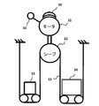
- FIG. 1 is a diagram for explaining a configuration of an elevator control device according to a first embodiment of the present invention.
- a sheave 32 is connected to the rotating shaft of the motor 31.
- a rope 33 is hung on the sheave 32.
- a car 34 is connected to one end of the rope 33, and a balance weight 35 is connected to the other end.
- the rope 33 is not limited to a rope having a round cross section, but also includes, for example, a rope having a belt shape.
- An encoder 30 for detecting an angle is connected to the motor 31 to which the sheave 32 is connected. With this encoder 30, angle information regarding the rotation angle of the motor 31 can be obtained.
- the speed control system is configured based on this angle information.
- the elevator mechanical system is composed of the components of reference numerals 30 to 36.
- the elevator mechanical system shown in FIG. 1 has a configuration called a one-to-one roping system.
- the elevator mechanical system to be controlled is 1: 1 shown in FIG.
- an n-to-1 roping system (where n ⁇ 2) may be used. Therefore, for reference, FIG. 2 shows an elevator mechanical system having a configuration called a 2: 1 roping system.
- n to 1 roping system (however, n ⁇ 2)
- the influence of the weight of the car 34 including the load inside the car on the motor torque is n minutes as compared with the 1 to 1 roping system. It should be noted that it becomes 1 of.
- the basic part of the technical content described below for the one-to-one roping system can be applied similarly to the n-to-1 roping system.
- the motor angle detection signal as the angle information, which is the output of the encoder 30, is input to the speed calculation unit 12.
- the speed calculation unit 12 has a function of converting the motor angle detection signal into the angular velocity signal of the motor 31, and outputs the speed signal ⁇ .
- the subtraction unit 14 performs a process of subtracting the speed signal ⁇ from the speed command signal ⁇ _ref, which is the output of the speed command generation unit 13, to obtain the speed deviation signal ⁇ _err.
- the speed deviation signal ⁇ _err is input to the speed control unit 15 configured to obtain desired tracking performance by speed control.
- the speed control unit 15 is realized by a typical PID control.
- the speed control signal iq_ ⁇ _cont which is the result of proportional / integral / differential calculation with respect to the speed deviation signal ⁇ _err, is output.
- the addition unit 16 adds the speed control signal iq_ ⁇ _cont and the unbalanced torque estimation signal iq_t * _off (Tmes) described later, and outputs the torque current command signal iq_t * which is the addition result.
- This unbalanced estimation signal iq_t * _off (Tmes) is output by the unbalanced torque estimation unit 17.
- the unbalanced torque estimation signal is described as iq_t * _off.
- it is expressed as iq_t * _off (Tmes) because it depends on Tmes which is time information as a parameter. This Tmes is information about a time called a first time, which will be described later.
- the torque / current command signal iq_t * is input to the current control unit 9.
- the current control unit 9 controls the motor drive current signal iq from the current detection unit 10 so as to follow the input torque current command signal iq_t *. Therefore, the current control unit 9 normally outputs a drive current iq that matches the torque current command signal iq_t * to the motor 31.
- the torque current command signal iq_t * _off Tmes
- the torque current command signal iq_t input to the current control unit 9 * Indicates the speed control signal iq_ ⁇ _cont, which is the output of the speed control unit 15.
- the torque current command signal iq_t * coincides with the speed control signal iq_ ⁇ _cont.
- the speed control system is realized so that the speed ⁇ of the motor 31 follows the speed command signal ⁇ _ref. Since the speed signal and the speed command signal described here are signals related to the angle, strictly speaking, they should be called the angular velocity signal and the angular velocity command signal, respectively. However, for convenience, they are referred to as a speed signal and a speed command signal only when there is no misunderstanding about them.
- the brake 36 has two operating states of braking and releasing the brake with respect to the motor 31. In the following, this braking release will be simply referred to as release.
- this braking release will be simply referred to as release.
- the brake control signal BK_cont output from the brake state command generation unit 7 to the brake control unit 8, it is possible to switch between the braking and the released state of the brake 36.
- the speed control system described above is changed from the disabled state to the enabled state.
- the speed command generation unit 13 sets the speed command signal ⁇ _ref in the valid state to zero.
- the speed control that controls the speed of the motor 31 by setting the speed command signal to zero is referred to as zero speed control here.
- the unbalanced torque estimation unit 17 estimates the unbalanced torque in the motor 31 due to the weight difference between the car 34 and the balance weight 35.
- the unbalanced torque estimation signal iq_t * _off (Tmes) estimated and output by the unbalanced torque estimation unit 17 is used to realize a control method for canceling the unbalanced torque. If the unbalanced torque can be canceled, the step-like input disturbance to the motor 31 will not occur. Since the sheave 32 and the car 34 are in a stable state without moving when the brake is released, the occurrence of start-up shock and rollback can be suppressed.
- the unbalanced torque estimation unit 17 has a function of inputting a speed signal ⁇ and a brake control signal BK_cont and outputting an unbalanced torque estimation signal iq_t * _off (Tmes).
- a special technical feature of the elevator control device according to the first embodiment of the present invention and the second embodiment described later is that the unbalanced torque can be easily generated by using the speed signal ⁇ and the brake control signal BK_cont. The point is that it utilizes a new finding that the unbalanced torque estimation signal required for cancellation can be obtained. This feature appears in the data shown in FIG. FIG. 3 is a diagram showing the relationship between the unbalanced torque and the time information defined by a certain definition.
- the time information defined by this certain definition is that the operating state of the brake 36 is switched from the braking state to the open state from the output change of the brake state command signal for switching the operating state of the brake 36 from the braking state to the open state. This is the time until the motor 31 starts the rotational operation.
- it is simply called the first time TMes.
- FIG. 11 is a diagram showing an example of time waveforms of various signals when the braking characteristics change when there is no load in the car and there is no start-up shock suppression control.
- the operating state of the brake 36 is braked from the output change of the brake state command signal for switching the operating state of the brake 36 from the braking state to the open state. It is the time until the motor 31 starts the rotational operation after switching from the state to the open state.
- FIG. 3 shows the relationship between the unbalanced torque [Nm] and the first Tmes [s] based on the actually measured data.
- the horizontal axis is the unbalanced torque
- the vertical axis is the first time TMes.
- the domain of the horizontal axis is from ⁇ Tq to ⁇ Tq.
- ⁇ Tq indicates Tq multiplied by ⁇ .
- Tq indicates the unbalanced torque amount when the rated load capacity is loaded
- ⁇ indicates the ratio of the load limit amount to the rated load capacity.
- FIG. 3 was created by conducting an experiment in which weights were piled up in the car 34 and the load in the car 34 was changed, and the relationship between the unbalanced torque at that time and the first time TMes was plotted. ..
- the values of the first time TMes are t1, t2, and t3 [s], indicating the following.
- t1 indicates the value of the first time TMes when the load capacity of the car 34 is the rated load capacity.
- t2 indicates the value of the first time TMes when the load amount of the car 34 is the balance load amount (the amount that balances with the balance weight 35).
- t3 indicates the value of the first time TMes when the loading amount of the car 34 is the loading limit amount.
- the characteristic waveform shown by the solid line in FIG. 3 can be approximated to a linear function in which the horizontal axis is the unbalanced torque and the vertical axis is the first time Tmes, excluding the range from Tq to ⁇ Tq in the domain of the horizontal axis. It can be confirmed that the characteristic is line-symmetric with respect to the vertical axis.
- the value of the first time TMes decreases linearly as the absolute amount of the unbalanced torque increases.
- the point showing t2 [s], which is the maximum value of the first time Tmes in FIG. 3, indicates the first time Tmes when the unbalanced torque is zero, that is, when the balance is achieved.
- the point indicating this t2 [s] is a virtual point obtained by linear approximation. This is clear from the fact that when the unbalanced torque is completely zero, i.e. balanced, the first time Times should be essentially infinite time.
- the characteristic waveform shown by the solid line in FIG. 3 can be a linear function in which the horizontal axis is the unbalanced torque and the vertical axis is the first time TMes.
- it may be a monotonic increase function when the domain of the horizontal axis is negative, and a monotonic decrease function when the domain of the horizontal axis is positive.
- the characteristic waveform described here is generally a function having a one-to-one correspondence.
- a one-to-one correspondence function has a feature that the value on the vertical axis uniquely corresponds to the value on the horizontal axis and the value on the horizontal axis uniquely corresponds to the value on the vertical axis. It is a function that has.
- the unbalanced torque can be estimated if the value of the first time TMes [s] and the sign of the unbalanced torque are known.
- the first time Tmes [s] can be measured.
- the sign of the unbalanced torque can be determined by the sign of the speed signal ⁇ obtained when the motor 31 starts the rotational operation when the brake 36 is released. Therefore, it is clear from FIG. 3 that the unbalanced torque can be estimated using these two pieces of information.
- the elevator control device can be used as two pieces of information in the zero speed control in which the speed command signal is set to zero to control the speed of the motor 31.
- the first time from the output change of the brake state command signal for switching the operating state of the brake 36 from the braking state to the released state until the motor 31 starts the rotational operation with the release of the brake 36, and the motor 31.
- This is realized by utilizing the fact that the unbalanced torque in the motor 31 due to the weight difference between the car 34 and the balance weight 35 can be estimated based on the positive and negative signs in the speed signal obtained when the brake starts the rotation operation. It is a thing.
- the timing at which the motor 31 starts the rotational operation when the brake 36 is released is, in a physical sense, the timing at which the operating state of the brake 36 changes from the static friction state to the dynamic friction state. Therefore, it can be said that it is the timing of changing the braking state. Therefore, in other words, the definition of the first time Tmes is that the first time Tmes is the time from the brake release command, which is the brake state command, to the brake state change timing. At this time, it can be seen that the information inside the brake 36 that it is in the static friction state is a state in which the speed signal ⁇ is zero as external information.
- the brake state change timing which is the timing at which the internal state of the brake 36 changes from the static friction state to the dynamic friction state, is a value other than zero when the speed signal ⁇ is zero as external information. It can be seen that it is the timing to change to the state of having.
- the brake state change timing can be detected as external information as the timing when the motor 31 starts the rotational operation when the brake 36 is released.
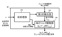
- FIG. 4 is a configuration diagram of an unbalanced torque estimation unit 17 in the elevator control device according to the first embodiment of the present invention.
- the unbalanced torque estimation unit 17 includes a pretreatment unit 171, a second detection unit 172, and a correction torque function unit 174.
- the preprocessing unit 171 includes a first detection unit (not shown) for detecting the brake state change timing and a first determination unit (not shown) for determining the positive / negative of the unbalanced torque code. It is a waste.
- the second detection unit 172 detects the first time Tmes, which is the time from the brake release command to the brake state change timing.
- the correction torque function unit 174 is related by the correction torque function.
- the ⁇ input to the unbalanced torque estimation unit 17 may be a normal speed signal indicating a physical quantity of speed.
- speed information including two signals, A-phase output and B-phase output, which are incremental encoder outputs, may be used.
- the input ⁇ will be described as a speed signal.
- the speed signal ⁇ is input to the preprocessing unit 171 including the first detection unit (not shown) and the first determination unit (not shown).
- the first detection unit detects the brake state change timing. For example, the first detection unit detects the timing at which the input speed signal ⁇ changes from zero to a predetermined value other than zero, and detects the brake state change timing.
- the brake state change timing can be detected as external information as the timing when the motor 31 starts the rotational operation when the brake 36 is released. Therefore, in addition to the speed signal ⁇ just described, the detection method as the brake state change timing includes, for example, an output signal of the rotation amount detection unit 30, a speed control signal output by the speed control unit 15, and current detection.
- the timing when a change indicating the rotational operation of the motor 31 appears in at least one of the drive current signal iq obtained from the unit 10 and the torque current command signal iq_t * input to the current control unit 9 may be used. ..
- the second detection unit 172 detects the first time Tmes, and detects the brake state change timing detection signal as the first time Tmes starting from the timing of the brake release command based on the brake control signal BK_cont. Detect the time to time.
- the first determination unit determines the sign of the unbalanced torque code, but more accurately, determines the sign of the speed signal ⁇ at the time of change of the brake state change timing detection signal. Specifically, it determines the rotation direction of the motor 31 when the operating state of the brake 36 changes from the static friction state to the dynamic friction state, and outputs the rotation direction information sign.
- the rotation direction information sign outputs +1 or -1, respectively, depending on whether the rotation direction is positive rotation or negative rotation.
- the correction torque function unit 174 outputs an unbalanced torque estimation signal iq_t * _off (Tmes) based on the sign of the rotation direction information by inputting the first time Tmes and the rotation direction information sign.
- the correction torque function unit 174 is a function that depends on the rotation direction of the motor 31 when the operating state of the brake 36 changes from the static friction state to the dynamic friction state. 5 and 6 show the characteristics of the correction torque function unit 174.
- the processing unit 171 will be described with reference to FIG. 7.
- the second detection unit 172 and the correction torque function unit 174 are the same as those described above assuming that the input ⁇ is a speed signal, and thus the description thereof will be omitted here.
- ⁇ input to the unbalanced torque estimation unit 17 is assumed to be velocity information including two signals, A-phase output and B-phase output, which are incremental encoder outputs. At this time, it is well known that the A-phase output signal and the B-phase output signal are out of phase by 90 degrees.
- the preprocessing unit 171 determines the positive / negative of the unbalanced torque code with the first detecting unit (not shown) that detects the brake state change timing. It includes a first determination unit (not shown) for determination. Therefore, the first detection unit starts the rotation operation of the motor 31 in accordance with the brake release by the brake state command for switching the operation state of the brake 36 from the braking state to the release information, so that the A-phase output and the B-phase output are output.
- the brake state change timing is detected based on when a change appears in the two signals.
- the brake state change timing can be detected as external information as the timing when the motor 31 starts the rotational operation when the brake 36 is released. Therefore, as another detection method as the brake state change timing, for example, it is input to the speed control signal output by the speed control unit 15, the drive current signal iq available from the current detection unit 10, and the current control unit 9. The timing when a change indicating the rotational operation of the motor 31 appears in at least one of the torque / current command signals iq_t * may be used.
- the first determination unit determines the rotation direction of the encoder, that is, the motor 31 to which the encoder is connected, depending on which of the rise timings of the A-phase output signal and the B-phase output signal comes first. Since the rotation direction of the unbalanced torque code can be determined, the positive / negative of the unbalanced torque code is determined.
- the upper figure of FIG. 7 shows the incremental encoder output when the rotation direction of the encoder is forward rotation. The figure below shows the incremental encoder output when the rotation direction of the encoder is negative.
- FIG. 5 and 6 are diagrams for explaining the correction torque function unit 174, which is one element constituting the unbalanced torque estimation unit 17 in the elevator control device according to the first embodiment of the present invention.
- FIG. 5 is a diagram for explaining the correction torque function unit 174 based on the correction torque function used when the rotation direction of the motor 31 is negative.
- FIG. 6 is a diagram for explaining the correction torque function unit 174 based on the correction torque function used when the rotation direction of the motor 31 is positive.
- FIGS. 5 and 6 are specifically diagrams showing a correction torque function calculated in the correction torque function unit 174.
- the correction torque function is an unbalanced torque estimation signal iq_t * _off (Tmes) corresponding to the measured first time Tmes when the rotation direction of the motor 31 is negative. It shows the relationship of.
- the horizontal axis is Tmes [s]
- the vertical axis is iq_t * _off (Tmes)
- the domain is 0 or more, and the range is 0 to ⁇ Tq.
- the horizontal axis is Tmes [s] and the vertical axis is iq_t * _off (Tmes), as in FIG.
- the domain is zero or more, and the range is from ⁇ Tq to zero, which is different from FIG.
- the symbols used in FIGS. 5 and 6 mean the same contents as those used in the explanation of FIG.
- the value of iq_t * _off (Tmes), which is the value of the correction torque function, is a constant value of ⁇ Tq from zero to t3 [s] in Tmes, and is a linear function from t3 to t2 in Tmes. Decreases with characteristics.
- the slope of the linear function at this time is ⁇ Tq / (t2-t1).
- the value of iq_t * _off (Tmes) when Tmes is t2 [s] is 0. Further, even if Tmes is t2 [s] or more, the value of iq_t * _off (Tmes) is defined as 0.
- the details of the correction torque function shown in FIG. 6 are as follows.
- the value of iq_t * _off (Tmes) which is the value of the correction torque function, is a constant value of ⁇ Tq from zero to t1 [s] of Tmes, and is primary when Tmes is from t1 to t2. Increases with function characteristics.
- the value of iq_t * _off (Tmes) when Tmes is t2 [s] is zero. Further, even if Tmes is t2 [s] or more, the value of iq_t * _off (Tmes) is defined as zero.
- FIG. 3 is a diagram showing the relationship between the unbalanced torque and the first time TMes.
- the vertical axis and the horizontal axis of FIG. 3 are interchanged, and the unbalanced torque that becomes the new vertical axis is defined as the unbalanced torque estimation signal.
- FIG. 5 shows a case where the unbalanced torque estimation signal is positive.
- FIG. 6 shows a case where the unbalanced torque estimation signal is negative.
- the unbalanced torque can be estimated by using the correction torque function calculated in the correction torque function unit 174 shown in FIG. 5 or FIG. That is, assuming that the measured first time TMes is, for example, Tn [s], when the sign of the rotation direction information at this time is positive or negative, the correction torque function shown in FIG. 6 is negative.
- the correction torque function shown in FIG. 5 is selected for, and as is clear from the correspondence of the correction torque function shown in FIG. 5 or FIG. 6 which is the selected figure, the corresponding iq_t when Tmes is Tn [s].
- * Tqn, which is the value of _off (Tmes) can be obtained.
- Tqn which is the value of iq_t * _off (Tmes) obtained when the first time Tmes is Tn [s] can be estimated as an unbalanced torque estimation signal.
- FIG. 8 is a diagram showing time waveforms of various signals in the elevator control device according to the first embodiment of the present invention. Note that FIG. 8 shows the behavior when there is no load inside the car as an initial condition, and as a result, a step disturbance due to an unbalanced torque is input to the motor 31. The contents shown here are what we have confirmed by simulation and actual equipment.
- the time waveforms of the four various signals shown in FIG. 8 relate to the brake control signal BK_cont (t), the velocity signal ⁇ (t), the torque current command signal iq_t *, and the vertical acceleration of the car 34 in order from the top. is there.
- the behavior of various signals after the first time Tmes [s] has elapsed since the release command was output by the brake control signal BK_cont (t) is as follows.
- the velocity signal ⁇ (t) keeps zero after a slight fluctuation.
- the torque / current command signal iq_t * has a stepped waveform, indicating that the unbalanced torque can be corrected instantly and appropriately.
- the vertical acceleration of the car 34 becomes a waveform obtained by differentiating the velocity signal ⁇ (t), it also keeps zero after a slight fluctuation. From the result of the vertical acceleration of the car 34, according to the elevator control device according to the first embodiment of the present invention, even when a step disturbance due to an unbalanced torque is input to the motor 31. It can be seen that the start-up shock and rollback can be suppressed extremely small.
- the output change of the brake state command signal for switching the operating state of the brake 36 from the braking state to the open state From, based on the first time until the motor 31 starts the rotation operation with the release of the brake 36, and the positive and negative signs in the speed signal obtained when the motor 31 starts the rotation. This is based on the new finding that the balance torque can be estimated. According to this, the estimation calculation of the unbalanced torque in the elevator control device according to the first embodiment of the present invention has simple characteristics instead of forming and calculating the disturbance observer as in the conventional case.
- the elevator control device According to the configuration of, it is possible to have a sufficient responsiveness for suppressing the influence of the unbalanced torque.
- Embodiment 2 The elevator control device according to the first embodiment of the present invention has, for example, an effective configuration when the characteristics of the brake 36 do not change significantly.
- the elevator control device according to the second embodiment of the present invention even if the characteristics of the brake 36 change due to the influence of temperature or the like during the operation of the elevator system, a start shock or a start shock occurs. This is to realize that the rollback can be suppressed to be small.
- FIG. 9 is a diagram for explaining an elevator control device according to a second embodiment of the present invention.
- the elevator control device according to the second embodiment of the present invention is intended for an elevator control device assuming a case where the characteristics of the brake 36 are changed.
- the portion of the unbalanced torque estimation unit 17 in the first embodiment shown in FIG. 1 is replaced with the unbalanced torque estimation unit 17a with an update function.
- Other configurations are the same as those of the elevator control device according to the first embodiment shown in FIG. Therefore, here, the description will focus on the unbalanced torque estimation unit 17a with an update function, which is a changed part.
- the unbalanced torque estimation unit 17a with an update function has, as input signals, a speed control signal iq_ ⁇ _cont which is an output of the speed control unit 15 and a zero speed control end timing signal which can be obtained from the speed command generation unit 13a.
- Zero_cont_end (t) is newly added. These newly added signals are used to deal with changes in the characteristics of the brake 36, which is a problem in the elevator control device according to the embodiment of the present invention.
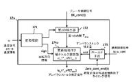
- FIG. 10 is a configuration diagram of an unbalanced torque estimation unit 17a with an update function in the elevator control device according to the second embodiment of the present invention.
- a block diagram showing an example of the unbalanced torque estimation unit 17a with an update function is shown.
- the correction torque function 174a with an update function is compared with the configuration of the unbalanced torque estimation unit 17 in the first embodiment shown in FIG.
- the holding means 175 are different in two configurations.
- FIG. 11 shows the time waveforms of various signals when the braking characteristics change when an unbalanced torque is generated due to no load in the car 34 and when suppression control for starting shock or rollback is not performed. It is a figure which shows an example.
- the time waveforms of the five various signals shown in FIG. 11 are, in order from the top, brake control signal BK_cont (t), speed signal ⁇ (t), speed control signal iq_ ⁇ _cont, vertical acceleration of the car 34, and zero immediately after activation.
- the speed control signal iq_ ⁇ _cont becomes zero when the unbalanced torque estimation signal iq_t * _off (Tmes) can be accurately estimated.
- the speed control signal iq_ ⁇ _cont has a value of crct as shown in FIG. That is, it can be understood that an error of crct occurs in the speed control signal iq_ ⁇ _cont due to the characteristic change in the brake 36.
- the value crct can be considered as a correction amount for compensating for an error in the speed control signal iq_ ⁇ _cont.
- the torque which is the detected value of the speed control signal iq_ ⁇ _cont when the speed signal ⁇ converges to zero by the zero speed control is obtained.
- the unbalanced torque estimation signal iq_t * _off (Tmes) can be used as a correction amount.
- the hold means 175 shown in FIG. 10 is used.
- the zero speed control end timing signal Zero_cont_end (t) obtained from the speed command generation unit 13a is used as the timing at which the speed signal ⁇ converges to zero by the zero speed control. It is also possible to use the velocity signal ⁇ instead of using the command, and use the signal obtained by determining whether or not the velocity signal ⁇ has converged to zero velocity.
- FIG. 12 is a diagram for explaining the correction torque function unit 174a with an update function, which is one element constituting the unbalanced torque estimation unit 17a with an update function in the elevator control device according to the second embodiment of the present invention. It is a figure of. Of these, FIG. 12 is a diagram for explaining the correction torque function unit 174a with an update function based on the correction torque function used when the rotation direction of the motor 31 is positive. On the other hand, FIG. 13 is a diagram for explaining the correction torque function unit 174a with an update function based on the correction torque function used when the rotation direction of the motor 31 is negative.
- the white circle points in FIGS. 12 and 13 indicate the break points in the correction torque function before the update. Suppression control against start-up shock and rollback by the elevator control device according to the first embodiment of the present invention using the pre-update correction torque function having the characteristic determined by the two white circle points in each of FIGS. 12 and 13.
- Tmes the unbalanced torque estimation signal iq_t * _off
- FIG. 13 may be replaced with FIG. 12 shown below.
- the update operation first, in the correction torque function shown in FIG. 12, it is obtained by connecting the white circle points at the coordinates (t2, 0) and the black circle points at the coordinates (tn, -Tqn + crct) with a straight line. First, find the black circle point at the break point coordinates (t1', -Tq). Next, the correction torque function obtained by connecting the black circle points at the break point coordinates (t1', -Tq) and the white circle points at the coordinates (t2, 0) with a straight line is updated as a new correction torque function. To do.
- the correction torque function unit 174a with an update function in the elevator control device according to the second embodiment of the present invention.
- the update operation of the correction torque function does not pose a big problem even if it is assumed that t2, which is a point in the correction torque function, does not change before and after the update.
- the absolute value in the estimated value of the unbalanced torque amount is relatively small in the former case and large in the latter case when comparing the case where the horizontal axis Tmes is near t2 and the case where the horizontal axis Tmes is tun. This is because it can be said that the value of the modeling error in the vicinity of t2 has less influence on the latter case than on the former case.
- FIG. 10 is a configuration diagram of an unbalanced torque estimation unit 17a with an update function in the elevator control device according to the second embodiment of the present invention
- the operation sequence with the passage of time can be understood from FIG. It's difficult to do.
- FIG. 14 is a diagram showing a time axis waveform for understanding the processing timing of various signals when the elevator car 34 moves up and down in the elevator control device according to the second embodiment of the present invention.
- the time waveforms of the four various signals shown in FIG. 14 are, in order from the top, a brake control signal BK_cont (t), a speed signal ⁇ (t), an unbalanced torque correction amount crct (t), and an unbalanced torque estimation signal iq_t. * It is related to _off (t).
- the white triangle mark indicates the timing of the first time Tmes, and indicates the timing at which the first time Tmes has elapsed from the rise of BK_cont (t).
- the black triangle mark is the rising timing of Zero_cont_end (t), which is the zero speed control end timing signal immediately after the start-up.
- the horizontal line triangle mark is the update timing of the unbalanced torque estimation signal iq_t * _off (t).
- the operating state of the elevator is shown by using a horizontal arrow. Further, below this horizontal arrow, the name of the operating state is shown.
- the black horizontal arrow indicates the stop period, which is the period during which the elevator is stopped. In this example, this suspension period is defined as the period from the horizontal line triangle mark to the white triangle mark.
- the white horizontal arrow indicates a moving period, which is a period in which the car 34 is moving and moving. In this example, it is defined as the period from the white triangle mark to the horizontal line triangle mark.
- stop in stop period 1 move to the upper floor in move period 1, stop in stop period 2, move to the lower floor in move period 2, and stop in stop period 3. Then, it moves to the upper floor in the movement period 3 and stops in the stop period 4.
- the speed control signal iq_ ⁇ _cont (t) is held by the holding means 175 at the timing of the black triangle mark 1, and the unbalanced torque correction amount crct is measured.
- the measured value of crct in this case is cr1.
- the crct is input to the correction torque function unit 174a with an update function.
- the correction torque function unit 174a with an update function updates the correction torque function based on crct, and this update operation is performed during the stop period 2.
- the update is performed at the start timing of the stop period 2, but it goes without saying that any timing may be used during the stop period 2.
- the updated unbalanced torque estimation signal iq_t * _off (t) becomes a value obtained by adding cr1 to the value before correction.
- the state of stopping in the stop period 2 shifts to the movement period 2, the speed control signal iq_ ⁇ _cont (t) is held by the hold means 175 at the timing of the black triangle mark 2, and the unbalanced torque correction amount crct is measured.
- the measured value of crct in this case is cr2.
- the sign of cr2 is negative.
- crct is input to the correction torque function unit 174a with an update function, and the correction torque function is updated at an arbitrary timing of the stop period 3.
- the updated unbalanced torque estimation signal iq_t * _off (t) becomes a value obtained by adding cr2 to the value before correction. Since the sign of cr2 in this example is negative, the value is obtained by subtracting the amplitude of cr2 from the value before correction.
- the speed control signal iq_ ⁇ _cont (t) is held by the hold means 175 at the timing of the black triangle mark 3, and the unbalanced torque correction amount crct is measured. ..
- the measured value of crct in this case is zero.
- the measured value of the unbalanced torque correction amount crct is zero.
- crct is input to the correction torque function unit 174a with an update function, and the correction torque function is updated at an arbitrary timing of the stop period 3, but as a result, the unbalanced torque estimation signal iq_t * _off after the update.
- (T) is the same value as the value before the update.
- the unbalanced torque estimation unit 17a with an update function becomes unbalanced. Since the correction torque function for estimating the torque as an unbalanced torque estimation signal can be appropriately updated, as a result, it is possible to suppress start-up shock and rollback to a small extent.
- the unbalanced torque estimation calculation is the same as the conventional disturbance, as in the elevator control device according to the first embodiment of the present invention. Since it is possible to perform calculations based on correspondence relationships represented by functions having simple characteristics, rather than constructing an observer for calculation, it is possible to realize a smaller calculation load of a calculation means such as a microcomputer as compared with the conventional case. It has the effect of. Further, the torque current command signal iq_t * has a stepped waveform, and the unbalanced torque can be corrected instantly and appropriately. Therefore, according to the configuration of the elevator control device according to the second embodiment of the present invention, the present invention. Similar to the control device for the elevator according to the first embodiment, the effect is that it can have sufficient responsiveness to suppress the influence of the unbalanced torque.
Landscapes
- Engineering & Computer Science (AREA)
- Automation & Control Theory (AREA)
- Elevator Control (AREA)
Abstract
Priority Applications (6)
| Application Number | Priority Date | Filing Date | Title |
|---|---|---|---|
| PCT/JP2019/013995 WO2020202249A1 (fr) | 2019-03-29 | 2019-03-29 | Dispositif de commande d'ascenseur |
| DE112019007113.0T DE112019007113T5 (de) | 2019-03-29 | 2019-03-29 | Aufzugssteuerungsvorrichtung |
| KR1020217030213A KR102513401B1 (ko) | 2019-03-29 | 2019-03-29 | 엘리베이터의 제어 장치 |
| JP2021510593A JP7058799B2 (ja) | 2019-03-29 | 2019-03-29 | エレベーターの制御装置 |
| US17/431,431 US20220135367A1 (en) | 2019-03-29 | 2019-03-29 | Elevator control device |
| CN201980094488.XA CN113614014B (zh) | 2019-03-29 | 2019-03-29 | 电梯控制装置 |
Applications Claiming Priority (1)
| Application Number | Priority Date | Filing Date | Title |
|---|---|---|---|
| PCT/JP2019/013995 WO2020202249A1 (fr) | 2019-03-29 | 2019-03-29 | Dispositif de commande d'ascenseur |
Publications (1)
| Publication Number | Publication Date |
|---|---|
| WO2020202249A1 true WO2020202249A1 (fr) | 2020-10-08 |
Family
ID=72666620
Family Applications (1)
| Application Number | Title | Priority Date | Filing Date |
|---|---|---|---|
| PCT/JP2019/013995 Ceased WO2020202249A1 (fr) | 2019-03-29 | 2019-03-29 | Dispositif de commande d'ascenseur |
Country Status (6)
| Country | Link |
|---|---|
| US (1) | US20220135367A1 (fr) |
| JP (1) | JP7058799B2 (fr) |
| KR (1) | KR102513401B1 (fr) |
| CN (1) | CN113614014B (fr) |
| DE (1) | DE112019007113T5 (fr) |
| WO (1) | WO2020202249A1 (fr) |
Families Citing this family (1)
| Publication number | Priority date | Publication date | Assignee | Title |
|---|---|---|---|---|
| CN115594056B (zh) * | 2022-09-30 | 2024-10-18 | 深圳市中金岭南有色金属股份有限公司凡口铅锌矿 | 提升容器的速度控制方法、装置及系统 |
Citations (9)
| Publication number | Priority date | Publication date | Assignee | Title |
|---|---|---|---|---|
| JPS638362B2 (fr) * | 1982-05-26 | 1988-02-22 | Sanyo Electric Co | |
| JPS63306175A (ja) * | 1987-06-04 | 1988-12-14 | 三菱電機株式会社 | エレベ−タの制御装置 |
| US4852694A (en) * | 1988-04-19 | 1989-08-01 | Hitachi, Ltd. | Elevator starting compensation method and apparatus |
| JPH0772060B2 (ja) * | 1985-09-03 | 1995-08-02 | 株式会社日立製作所 | エレベ−タ−の起動補償装置 |
| JP2510685B2 (ja) * | 1988-07-30 | 1996-06-26 | 株式会社日立製作所 | エレベ―タの起動補償装置 |
| JP2513792B2 (ja) * | 1988-07-13 | 1996-07-03 | 株式会社日立ビルシステムサービス | インバ―タエレベ―タの起動方法 |
| JP4419517B2 (ja) * | 2003-10-29 | 2010-02-24 | 富士電機システムズ株式会社 | 昇降機械駆動用電動機の制御方法 |
| JP2016183048A (ja) * | 2015-03-26 | 2016-10-20 | 三菱電機株式会社 | エレベータ制御装置、エレベータ監視システム、及びエレベータ制御方法 |
| WO2018042920A1 (fr) * | 2016-08-29 | 2018-03-08 | 株式会社日立製作所 | Système d'ascenseur et procédé de commande s'y rapportant |
Family Cites Families (24)
| Publication number | Priority date | Publication date | Assignee | Title |
|---|---|---|---|---|
| JPS50149040A (fr) | 1974-05-22 | 1975-11-28 | ||
| CH652995A5 (de) * | 1980-04-21 | 1985-12-13 | Inventio Ag | Aufzugsantrieb mit anfahrsteuerung. |
| JPH0645430B2 (ja) * | 1988-12-07 | 1994-06-15 | 株式会社日立製作所 | エレベーター用巻上機のブレーキ装置及びそれを用いたエレベーター |
| DE4119253A1 (de) * | 1990-06-11 | 1991-12-12 | Mitsubishi Electric Corp | Aufzugssteuervorrichtung |
| US5076399A (en) * | 1990-09-28 | 1991-12-31 | Otis Elevator Company | Elevator start control technique for reduced start jerk and acceleration overshoot |
| JP3008362B2 (ja) * | 1992-09-21 | 2000-02-14 | 株式会社日立ビルシステム | エレベータの異常検出装置 |
| KR100312772B1 (ko) * | 1998-12-15 | 2002-11-22 | 엘지 오티스 엘리베이터 유한회사 | 엘리베이터의속도제어장치 |
| JP4010195B2 (ja) * | 2002-06-26 | 2007-11-21 | 株式会社日立製作所 | 永久磁石式同期モータの制御装置 |
| JP3817218B2 (ja) * | 2002-11-20 | 2006-09-06 | 三菱電機ビルテクノサービス株式会社 | エレベータのブレーキトルク測定装置および測定方法 |
| WO2005102895A1 (fr) * | 2004-03-30 | 2005-11-03 | Mitsubishi Denki Kabushiki Kaisha | Dispositif de contrôle d'ascenseur |
| JP4727234B2 (ja) * | 2005-01-14 | 2011-07-20 | 三菱電機株式会社 | エレベータ装置 |
| JP5228996B2 (ja) * | 2009-02-27 | 2013-07-03 | 日産自動車株式会社 | 電動車両の制振制御装置 |
| JP5322102B2 (ja) * | 2009-03-09 | 2013-10-23 | 東芝エレベータ株式会社 | エレベータ |
| DE112013004225B4 (de) * | 2012-08-29 | 2019-08-01 | Mitsubishi Electric Corporation | Aufzugs-Steuerungsvorrichtung und Aufzugs-Steuerungsverfahren |
| CN104649087B (zh) * | 2013-11-20 | 2016-06-15 | 上海三菱电梯有限公司 | 电梯控制装置 |
| CN104671022B (zh) * | 2013-11-26 | 2017-04-12 | 三菱电机株式会社 | 电梯的控制装置及电梯的控制方法 |
| JP6029777B2 (ja) * | 2014-02-06 | 2016-11-24 | 三菱電機株式会社 | エレベータ制御装置、エレベータシステム、およびエレベータ制御方法 |
| CN105775948B (zh) * | 2014-12-22 | 2018-01-30 | 日立电梯(中国)有限公司 | 一种电梯起动补偿方法 |
| EP3048074B1 (fr) * | 2015-01-26 | 2022-01-05 | KONE Corporation | Procédé permettant d'éliminer une secousse provoquée par l'accélération de la cabine d'ascenseur |
| JP6556353B2 (ja) * | 2016-06-30 | 2019-08-07 | 三菱電機株式会社 | エレベーターの制御装置 |
| JP6625497B2 (ja) * | 2016-07-20 | 2019-12-25 | 株式会社日立ビルシステム | 昇降機用ブレーキの異常診断装置および異常診断方法 |
| CN109982952B (zh) * | 2016-11-29 | 2021-09-24 | 三菱电机株式会社 | 电梯控制装置以及电梯控制方法 |
| WO2019008650A1 (fr) * | 2017-07-03 | 2019-01-10 | 三菱電機株式会社 | Dispositif de commande d'ascenseur et procédé de commande d'ascenseur |
| CN108173462B (zh) * | 2017-12-13 | 2020-06-26 | 天津津航计算技术研究所 | 一种两电机转矩平衡控制方法 |
-
2019
- 2019-03-29 KR KR1020217030213A patent/KR102513401B1/ko active Active
- 2019-03-29 US US17/431,431 patent/US20220135367A1/en active Pending
- 2019-03-29 DE DE112019007113.0T patent/DE112019007113T5/de active Pending
- 2019-03-29 CN CN201980094488.XA patent/CN113614014B/zh active Active
- 2019-03-29 JP JP2021510593A patent/JP7058799B2/ja not_active Expired - Fee Related
- 2019-03-29 WO PCT/JP2019/013995 patent/WO2020202249A1/fr not_active Ceased
Patent Citations (9)
| Publication number | Priority date | Publication date | Assignee | Title |
|---|---|---|---|---|
| JPS638362B2 (fr) * | 1982-05-26 | 1988-02-22 | Sanyo Electric Co | |
| JPH0772060B2 (ja) * | 1985-09-03 | 1995-08-02 | 株式会社日立製作所 | エレベ−タ−の起動補償装置 |
| JPS63306175A (ja) * | 1987-06-04 | 1988-12-14 | 三菱電機株式会社 | エレベ−タの制御装置 |
| US4852694A (en) * | 1988-04-19 | 1989-08-01 | Hitachi, Ltd. | Elevator starting compensation method and apparatus |
| JP2513792B2 (ja) * | 1988-07-13 | 1996-07-03 | 株式会社日立ビルシステムサービス | インバ―タエレベ―タの起動方法 |
| JP2510685B2 (ja) * | 1988-07-30 | 1996-06-26 | 株式会社日立製作所 | エレベ―タの起動補償装置 |
| JP4419517B2 (ja) * | 2003-10-29 | 2010-02-24 | 富士電機システムズ株式会社 | 昇降機械駆動用電動機の制御方法 |
| JP2016183048A (ja) * | 2015-03-26 | 2016-10-20 | 三菱電機株式会社 | エレベータ制御装置、エレベータ監視システム、及びエレベータ制御方法 |
| WO2018042920A1 (fr) * | 2016-08-29 | 2018-03-08 | 株式会社日立製作所 | Système d'ascenseur et procédé de commande s'y rapportant |
Also Published As
| Publication number | Publication date |
|---|---|
| JPWO2020202249A1 (ja) | 2021-10-14 |
| KR20210129158A (ko) | 2021-10-27 |
| JP7058799B2 (ja) | 2022-04-22 |
| CN113614014A (zh) | 2021-11-05 |
| KR102513401B1 (ko) | 2023-03-24 |
| DE112019007113T5 (de) | 2021-12-16 |
| US20220135367A1 (en) | 2022-05-05 |
| CN113614014B (zh) | 2023-08-29 |
Similar Documents
| Publication | Publication Date | Title |
|---|---|---|
| JP6878029B2 (ja) | 荷重検出装置及びそれを備えるクレーンの巻上装置 | |
| US7831333B2 (en) | Method for the automatic transfer of a load hanging at a load rope of a crane or excavator with a load oscillation damping and a trajectory planner | |
| JP5659727B2 (ja) | クレーン振れ角検出方法及び装置、並びにクレーン振れ止め制御方法及び装置 | |
| CN104520223B (zh) | 电梯的控制装置及电梯的控制方法 | |
| JP7058799B2 (ja) | エレベーターの制御装置 | |
| WO2016063379A1 (fr) | Appareil de commande d'ascenseur | |
| JP6984738B2 (ja) | 電動機の制御装置およびエレベータの制御装置 | |
| JP6556353B2 (ja) | エレベーターの制御装置 | |
| US11492231B2 (en) | Elevator apparatus | |
| JP2008044680A (ja) | エレベータの制御装置 | |
| JP2008304233A (ja) | 電気慣性制御方法 | |
| JP2021102503A (ja) | 懸架式クレーンの制御装置及びインバータ装置 | |
| CN110467072B (zh) | 用于电梯系统的启动力矩补偿方法及电梯系统 | |
| JPWO2021186680A5 (fr) | ||
| JP7168085B2 (ja) | エレベーターの制御装置 | |
| WO2019008650A1 (fr) | Dispositif de commande d'ascenseur et procédé de commande d'ascenseur | |
| JP5746373B2 (ja) | エレベーターの制御装置およびその制御方法 | |
| JP6390394B2 (ja) | エレベータ制御装置 | |
| JPH1160089A (ja) | 駆動の調節方法および装置 | |
| JP2772883B2 (ja) | クレーンの振れ止め・位置決め制御装置及び制御方法 | |
| JP2015000796A (ja) | エレベーター | |
| JP5642326B2 (ja) | クレーン又はバガーで吊り荷ロープに吊り下げられている吊り荷を自動的に積み替える方法 | |
| JPH11193190A (ja) | エレベータ速度制御装置 | |
| JP2007238231A (ja) | エレベータの制御装置 | |
| JP5200680B2 (ja) | 動力計システムの軸トルク制御方法 |
Legal Events
| Date | Code | Title | Description |
|---|---|---|---|
| 121 | Ep: the epo has been informed by wipo that ep was designated in this application |
Ref document number: 19922272 Country of ref document: EP Kind code of ref document: A1 |
|
| ENP | Entry into the national phase |
Ref document number: 2021510593 Country of ref document: JP Kind code of ref document: A |
|
| ENP | Entry into the national phase |
Ref document number: 20217030213 Country of ref document: KR Kind code of ref document: A |
|
| 122 | Ep: pct application non-entry in european phase |
Ref document number: 19922272 Country of ref document: EP Kind code of ref document: A1 |