WO2020255941A1 - 工作機械、工作機械の制御方法、および、工作機械の制御プログラム - Google Patents
工作機械、工作機械の制御方法、および、工作機械の制御プログラム Download PDFInfo
- Publication number
- WO2020255941A1 WO2020255941A1 PCT/JP2020/023508 JP2020023508W WO2020255941A1 WO 2020255941 A1 WO2020255941 A1 WO 2020255941A1 JP 2020023508 W JP2020023508 W JP 2020023508W WO 2020255941 A1 WO2020255941 A1 WO 2020255941A1
- Authority
- WO
- WIPO (PCT)
- Prior art keywords
- door
- opening
- machine tool
- open
- closing
- Prior art date
- Legal status (The legal status is an assumption and is not a legal conclusion. Google has not performed a legal analysis and makes no representation as to the accuracy of the status listed.)
- Ceased
Links
Images












Classifications
-
- G—PHYSICS
- G05—CONTROLLING; REGULATING
- G05B—CONTROL OR REGULATING SYSTEMS IN GENERAL; FUNCTIONAL ELEMENTS OF SUCH SYSTEMS; MONITORING OR TESTING ARRANGEMENTS FOR SUCH SYSTEMS OR ELEMENTS
- G05B19/00—Program-control systems
- G05B19/02—Program-control systems electric
- G05B19/18—Numerical control [NC], i.e. automatically operating machines, in particular machine tools, e.g. in a manufacturing environment, so as to execute positioning, movement or co-ordinated operations by means of program data in numerical form
- G05B19/19—Numerical control [NC], i.e. automatically operating machines, in particular machine tools, e.g. in a manufacturing environment, so as to execute positioning, movement or co-ordinated operations by means of program data in numerical form characterised by positioning or contouring control systems, e.g. to control position from one programmed point to another or to control movement along a programmed continuous path
-
- G—PHYSICS
- G05—CONTROLLING; REGULATING
- G05B—CONTROL OR REGULATING SYSTEMS IN GENERAL; FUNCTIONAL ELEMENTS OF SUCH SYSTEMS; MONITORING OR TESTING ARRANGEMENTS FOR SUCH SYSTEMS OR ELEMENTS
- G05B19/00—Program-control systems
- G05B19/02—Program-control systems electric
- G05B19/18—Numerical control [NC], i.e. automatically operating machines, in particular machine tools, e.g. in a manufacturing environment, so as to execute positioning, movement or co-ordinated operations by means of program data in numerical form
- G05B19/402—Numerical control [NC], i.e. automatically operating machines, in particular machine tools, e.g. in a manufacturing environment, so as to execute positioning, movement or co-ordinated operations by means of program data in numerical form characterised by control arrangements for positioning, e.g. centring a tool relative to a hole in the workpiece, additional detection means to correct position
-
- G—PHYSICS
- G05—CONTROLLING; REGULATING
- G05B—CONTROL OR REGULATING SYSTEMS IN GENERAL; FUNCTIONAL ELEMENTS OF SUCH SYSTEMS; MONITORING OR TESTING ARRANGEMENTS FOR SUCH SYSTEMS OR ELEMENTS
- G05B19/00—Program-control systems
- G05B19/02—Program-control systems electric
- G05B19/18—Numerical control [NC], i.e. automatically operating machines, in particular machine tools, e.g. in a manufacturing environment, so as to execute positioning, movement or co-ordinated operations by means of program data in numerical form
- G05B19/409—Numerical control [NC], i.e. automatically operating machines, in particular machine tools, e.g. in a manufacturing environment, so as to execute positioning, movement or co-ordinated operations by means of program data in numerical form characterised by using manual data input [MDI] or by using control panel, e.g. controlling functions with the panel; characterised by control panel details or by setting parameters
-
- E—FIXED CONSTRUCTIONS
- E05—LOCKS; KEYS; WINDOW OR DOOR FITTINGS; SAFES
- E05F—DEVICES FOR MOVING WINGS INTO OPEN OR CLOSED POSITION; CHECKS FOR WINGS; WING FITTINGS NOT OTHERWISE PROVIDED FOR, CONCERNED WITH THE FUNCTIONING OF THE WING
- E05F15/00—Power-operated mechanisms for wings
- E05F15/70—Power-operated mechanisms for wings with automatic actuation
-
- B—PERFORMING OPERATIONS; TRANSPORTING
- B23—MACHINE TOOLS; METAL-WORKING NOT OTHERWISE PROVIDED FOR
- B23Q—DETAILS, COMPONENTS, OR ACCESSORIES FOR MACHINE TOOLS, e.g. ARRANGEMENTS FOR COPYING OR CONTROLLING; MACHINE TOOLS IN GENERAL CHARACTERISED BY THE CONSTRUCTION OF PARTICULAR DETAILS OR COMPONENTS; COMBINATIONS OR ASSOCIATIONS OF METAL-WORKING MACHINES, NOT DIRECTED TO A PARTICULAR RESULT
- B23Q11/00—Accessories fitted to machine tools for keeping tools or parts of the machine in good working condition or for cooling work; Safety devices specially combined with or arranged in, or specially adapted for use in connection with, machine tools
- B23Q11/08—Protective coverings for parts of machine tools; Splash guards
- B23Q11/0891—Protective coverings for parts of machine tools; Splash guards arranged between the working area and the operator
-
- B—PERFORMING OPERATIONS; TRANSPORTING
- B23—MACHINE TOOLS; METAL-WORKING NOT OTHERWISE PROVIDED FOR
- B23Q—DETAILS, COMPONENTS, OR ACCESSORIES FOR MACHINE TOOLS, e.g. ARRANGEMENTS FOR COPYING OR CONTROLLING; MACHINE TOOLS IN GENERAL CHARACTERISED BY THE CONSTRUCTION OF PARTICULAR DETAILS OR COMPONENTS; COMBINATIONS OR ASSOCIATIONS OF METAL-WORKING MACHINES, NOT DIRECTED TO A PARTICULAR RESULT
- B23Q17/00—Arrangements for observing, indicating or measuring on machine tools
-
- E—FIXED CONSTRUCTIONS
- E05—LOCKS; KEYS; WINDOW OR DOOR FITTINGS; SAFES
- E05Y—INDEXING SCHEME ASSOCIATED WITH SUBCLASSES E05D AND E05F, RELATING TO CONSTRUCTION ELEMENTS, ELECTRIC CONTROL, POWER SUPPLY, POWER SIGNAL OR TRANSMISSION, USER INTERFACES, MOUNTING OR COUPLING, DETAILS, ACCESSORIES, AUXILIARY OPERATIONS NOT OTHERWISE PROVIDED FOR, APPLICATION THEREOF
- E05Y2400/00—Electronic control; Electrical power; Power supply; Power or signal transmission; User interfaces
- E05Y2400/10—Electronic control
- E05Y2400/32—Position control, detection or monitoring
-
- E—FIXED CONSTRUCTIONS
- E05—LOCKS; KEYS; WINDOW OR DOOR FITTINGS; SAFES
- E05Y—INDEXING SCHEME ASSOCIATED WITH SUBCLASSES E05D AND E05F, RELATING TO CONSTRUCTION ELEMENTS, ELECTRIC CONTROL, POWER SUPPLY, POWER SIGNAL OR TRANSMISSION, USER INTERFACES, MOUNTING OR COUPLING, DETAILS, ACCESSORIES, AUXILIARY OPERATIONS NOT OTHERWISE PROVIDED FOR, APPLICATION THEREOF
- E05Y2400/00—Electronic control; Electrical power; Power supply; Power or signal transmission; User interfaces
- E05Y2400/10—Electronic control
- E05Y2400/36—Speed control, detection or monitoring
-
- E—FIXED CONSTRUCTIONS
- E05—LOCKS; KEYS; WINDOW OR DOOR FITTINGS; SAFES
- E05Y—INDEXING SCHEME ASSOCIATED WITH SUBCLASSES E05D AND E05F, RELATING TO CONSTRUCTION ELEMENTS, ELECTRIC CONTROL, POWER SUPPLY, POWER SIGNAL OR TRANSMISSION, USER INTERFACES, MOUNTING OR COUPLING, DETAILS, ACCESSORIES, AUXILIARY OPERATIONS NOT OTHERWISE PROVIDED FOR, APPLICATION THEREOF
- E05Y2400/00—Electronic control; Electrical power; Power supply; Power or signal transmission; User interfaces
- E05Y2400/80—User interfaces
- E05Y2400/85—User input means
-
- E—FIXED CONSTRUCTIONS
- E05—LOCKS; KEYS; WINDOW OR DOOR FITTINGS; SAFES
- E05Y—INDEXING SCHEME ASSOCIATED WITH SUBCLASSES E05D AND E05F, RELATING TO CONSTRUCTION ELEMENTS, ELECTRIC CONTROL, POWER SUPPLY, POWER SIGNAL OR TRANSMISSION, USER INTERFACES, MOUNTING OR COUPLING, DETAILS, ACCESSORIES, AUXILIARY OPERATIONS NOT OTHERWISE PROVIDED FOR, APPLICATION THEREOF
- E05Y2400/00—Electronic control; Electrical power; Power supply; Power or signal transmission; User interfaces
- E05Y2400/80—User interfaces
- E05Y2400/85—User input means
- E05Y2400/851—Voice
-
- E—FIXED CONSTRUCTIONS
- E05—LOCKS; KEYS; WINDOW OR DOOR FITTINGS; SAFES
- E05Y—INDEXING SCHEME ASSOCIATED WITH SUBCLASSES E05D AND E05F, RELATING TO CONSTRUCTION ELEMENTS, ELECTRIC CONTROL, POWER SUPPLY, POWER SIGNAL OR TRANSMISSION, USER INTERFACES, MOUNTING OR COUPLING, DETAILS, ACCESSORIES, AUXILIARY OPERATIONS NOT OTHERWISE PROVIDED FOR, APPLICATION THEREOF
- E05Y2999/00—Subject-matter not otherwise provided for in this subclass
-
- G—PHYSICS
- G05—CONTROLLING; REGULATING
- G05B—CONTROL OR REGULATING SYSTEMS IN GENERAL; FUNCTIONAL ELEMENTS OF SUCH SYSTEMS; MONITORING OR TESTING ARRANGEMENTS FOR SUCH SYSTEMS OR ELEMENTS
- G05B19/00—Program-control systems
- G05B19/02—Program-control systems electric
- G05B19/42—Recording and playback systems, i.e. in which the program is recorded from a cycle of operations, e.g. the cycle of operations being manually controlled, after which this record is played back on the same machine
-
- G—PHYSICS
- G05—CONTROLLING; REGULATING
- G05B—CONTROL OR REGULATING SYSTEMS IN GENERAL; FUNCTIONAL ELEMENTS OF SUCH SYSTEMS; MONITORING OR TESTING ARRANGEMENTS FOR SUCH SYSTEMS OR ELEMENTS
- G05B2219/00—Program-control systems
- G05B2219/30—Nc systems
- G05B2219/35—Nc in input of data, input till input file format
- G05B2219/35349—Display part, programmed locus and tool path, traject, dynamic locus
-
- G—PHYSICS
- G05—CONTROLLING; REGULATING
- G05B—CONTROL OR REGULATING SYSTEMS IN GENERAL; FUNCTIONAL ELEMENTS OF SUCH SYSTEMS; MONITORING OR TESTING ARRANGEMENTS FOR SUCH SYSTEMS OR ELEMENTS
- G05B2219/00—Program-control systems
- G05B2219/30—Nc systems
- G05B2219/37—Measurements
- G05B2219/37618—Observe, monitor position, posture of tool
-
- G—PHYSICS
- G05—CONTROLLING; REGULATING
- G05B—CONTROL OR REGULATING SYSTEMS IN GENERAL; FUNCTIONAL ELEMENTS OF SUCH SYSTEMS; MONITORING OR TESTING ARRANGEMENTS FOR SUCH SYSTEMS OR ELEMENTS
- G05B2219/00—Program-control systems
- G05B2219/30—Nc systems
- G05B2219/45—Nc applications
- G05B2219/45242—Door, panel, window operation, opening, closing
Definitions
- This disclosure relates to a technique for controlling the drive of a door provided in a machine tool.
- Machine tools with doors are widespread.
- the door is closed when the work is machined and opened when the work is not machined. This prevents scattering of processed pieces and the like generated during processing.
- Patent Document 1 discloses a machine tool for the purpose of shortening the time required to close the door.
- the machine tool drives the door to a fixed open position when the door is opened, and drives the door to a fixed closed position when the door is closed.
- a machine tool has an opening, a cover for partitioning a machining area of a work, a door for covering the opening, and a drive mechanism for driving the door to change the degree of the opening.
- a detection unit for detecting the actual position of the door, an operation panel for receiving an operation on the machine tool, and a control device for controlling the machine tool are provided.
- the control device controls the drive mechanism so that the door opens based on the operation panel accepting the first opening operation of the door, and the operation panel determines the position of the door.
- the process of acquiring the actual position from the detection unit and storing the acquired actual position as the opening position of the door, and the operation panel performing the second opening operation of the door based on the acceptance of the above. Based on the acceptance, the process of controlling the drive mechanism so that the door is located at the open position is executed.
- the opening speed of the door during the first opening operation is slower than the opening speed of the door during the second opening operation.
- a method of controlling a machine tool has an opening, a cover for partitioning a machining area of a work, a door for covering the opening, a drive mechanism for driving the door to change the degree of the opening, and the door. It is provided with a detection unit for detecting an actual position and an operation panel for receiving an operation on the machine tool.
- the control method includes a step of controlling the drive mechanism so that the door opens based on the operation panel accepting the first opening operation of the door, and an operation of determining the position of the door by the operation panel.
- a step of controlling the drive mechanism so that the door is located at the open position based on the reception is provided.
- the opening speed of the door during the first opening operation is slower than the opening speed of the door during the second opening operation.
- a machine tool control program is provided.
- the machine tool has an opening, a cover for partitioning a machining area of a work, a door for covering the opening, a drive mechanism for driving the door to change the degree of the opening, and the door. It is provided with a detection unit for detecting an actual position and an operation panel for receiving an operation on the machine tool.
- the control program includes a step of controlling the drive mechanism so that the door is opened based on the machine tool receiving the first opening operation of the door, and the operation panel is described. Based on the acceptance of the door position determination operation, the step of acquiring the actual position from the detection unit and storing the acquired actual position as the open position of the door, and the operation panel are the first of the doors. Based on the acceptance of the opening operation of 2, the step of controlling the drive mechanism so that the door is located at the opening position is executed. The opening speed of the door during the first opening operation is slower than the opening speed of the door during the second opening operation.
- FIG. 1 is a diagram showing the appearance of the machine tool 100.
- machine tool is a concept that includes various devices having a function of processing a workpiece.
- a vertical machining center in which the workpiece to be machined is mounted on a fixed surface extending in the horizontal direction is described as an example, but the machine tool 100 is not limited to the vertical machining center. ..
- the machine tool 100 may be a horizontal machining center attached to a fixed surface on which the work to be machined extends in the vertical direction.
- the machine tool 100 may be a lathe, or another cutting machine or grinding machine.
- the machine tool 100 includes an operation panel 140.
- the operation panel 140 is a general-purpose computer, and has a display 142 for displaying various information related to processing.
- the display 142 is, for example, a liquid crystal display, an organic EL (Electro Luminescence) display, or other display device. Further, the display 142 is composed of a touch panel, and accepts various operations on the machine tool 100 by touch operations.
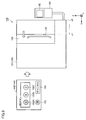
- FIG. 2 is a diagram showing the machine tool 100 from two directions. In the following, the door 136 provided in the machine tool 100 will be described with reference to FIG.
- the opening / closing direction of the door 136 is referred to as "X-axis direction”
- the horizontal direction orthogonal to the X-axis direction is referred to as “Y-axis direction”
- the X-axis direction and the Y-axis direction The direction orthogonal to both (that is, the direction of gravity) is referred to as the "Z-axis direction”.
- FIG. 2 (A) shows the machine tool 100 represented from the Z-axis direction.
- FIG. 2B shows the machine tool 100 represented from the Y-axis direction.
- the machine tool 100 includes a control device 40, a spindle 115, a table 116, a cover 131, a door 136, a drive mechanism 137, and a detection unit 138.
- the spindle 115 is provided so as to be movable inside the machining area AR1 of the work. Further, the spindle 115 is provided so as to be movable along the Z-axis direction. Further, the spindle 115 is rotatably provided about the central axis AX parallel to the Z axis by driving the motor. The spindle 115 is provided with a clamp mechanism for holding various tools detachably.
- the table 116 is provided so as to be movable inside the processing area AR1.
- the table 116 is provided so as to be movable in a plane (XY plane) including the X-axis direction and the Y-axis direction.
- a work mounting jig (not shown) for holding the work detachably is provided on the table 116. The work to be machined is fixed to the work mounting jig through the opening 132.
- the cover 131 which is also called a splash guard, has the appearance of the machine tool 100 and forms the processing area AR1 as a section.
- the cover 131 has an opening 132.
- the opening 132 opens from the front surface to the upper surface of the cover 131 and leads to the processing area AR1.
- the door 136 is provided so as to cover the opening 132, and is provided so as to be slidable along the X-axis direction.
- the opening 132 is set to a state in which it is not covered by the door 136 (open state), or the opening 132 is set to a state in which it is covered by the door 136 (closed state).
- the processing area AR1 is partitioned together with the cover 131.
- the door 136 is provided with a transparent window (not shown) for an operator to look into the processing area AR1.
- FIG. 2 shows a door 136 that is slid-driven in the horizontal direction, the door 136 may be slid-driven in the gravity direction (Z-axis direction). Further, the door 136 may be driven so as to slide and move on an arc.
- the operation of the door 136 when the opening area of the opening 132 increases is referred to as an "opening operation".
- the action of sliding the door 136 to the negative side in the X-axis direction corresponds to the "opening action”.
- the operation of the door 136 when the opening area of the opening 132 is reduced is referred to as a "closing operation”.
- the operation of sliding the door 136 to the positive side in the X-axis direction corresponds to the "closing operation”.
- the drive mechanism 137 is connected to the door 136.
- the drive mechanism 137 opens and closes the door 136 at an arbitrary position in the X-axis direction according to a drive command from the control device 40, and changes the degree of the opening 132.
- the type of motor included in the drive mechanism 137 is not particularly limited, but an example is a servo motor, a stepping motor, or a linear motor.
- the detection unit 138 is a sensor for detecting the actual position of the door 136 based on the driving amount of the door 136 by the drive mechanism 137.
- the type of the detection unit 138 is not particularly limited, but the detection unit 138 is, for example, an encoder.
- the actual position of the door 136 detected by the detection unit 138 is output to the control device 40.
- the door 136 is provided with a handle 139.
- the drive force does not act on the door 136.
- the user can grasp the handle 139 and manually move the door 136 in the X-axis direction.
- the door 136 can be driven by the drive mechanism 137 to any opening / closing position in the X-axis direction. In order to stop the door 136 at an arbitrary position, it is usually necessary to programmatically specify the opening / closing position of the door 136 or change the setting related to the opening / closing position of the door 136. Expertise is required to specify the open / close position by these methods. It is also difficult to intuitively understand the degree of opening and closing of the door.
- the machine tool 100 is provided with a function that allows the user to manually move the door 136 to specify the opening / closing position of the door 136. Since the user can actually move the door 136 to set the opening / closing position, the user can intuitively understand the opening / closing position. Further, the user does not need to rewrite the program or the setting in this setting process.
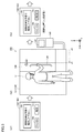
- FIG. 3 is a diagram showing the teaching process in chronological order.
- step S1 user U switches the operation mode of the machine tool 100 to the teaching mode (first mode). Based on this, the control device 40 of the machine tool 100 executes a process (hereinafter, also referred to as “manual request process”) for prompting the user U to manually move the door 136.
- the manual request processing can be realized by various means. As an example, the manual request processing may be realized by displaying a message on the display 142, may be realized by emitting a voice, or may emit a light source such as an LED (Light Emitting Diode). It may be realized by. In the example of FIG. 3, the manual request processing is realized by displaying the message 145 "Please specify the open / close position manually" on the setting screen 143.
- the control device 40 stops the supply of electric power to the drive mechanism 137 (see FIG. 2) described above while the manual request processing is being executed. More specifically, a power source (not shown) for supplying electric power is connected to the drive mechanism 137. When electric power is supplied from the power source to the drive mechanism 137, the driving force of the drive mechanism 137 acts on the door 136. On the other hand, when the electric power is not supplied to the drive mechanism 137 from the power source, the drive force of the drive mechanism 137 does not act on the door 136. The control device 40 stops the supply of electric power from the power source during the execution of the manual request processing. As a result, the driving force does not act on the door 136, and the user U can manually move the door 136.
- step S2 the user U grabs the handle 139, moves the door 136, and stops the door 136 at an arbitrary position in the X-axis direction.
- the user U moves the door 136 from the opening / closing position “x0” and stops the door 136 at the opening / closing position “x1”.
- step S3 it is assumed that the control device 40 receives the position determination instruction of the door 136 from the user U during the execution of the manual request processing.
- Positioning instructions can be input in various ways.
- the position determination instruction may be input by the user U pressing a specific button, or may be input by the user U emitting a predetermined voice.
- the specific button may be a software button displayed on the display 142, or may be a hardware button provided on the machine tool 100.
- the control device 40 acquires the actual position of the door 136 from the above-mentioned detection unit 138, and stores the acquired actual position as a set position related to opening and closing of the door 136.
- the set position "x1" is stored.
- the set position "x1" may be stored in a memory in the machine tool 100, or may be stored in a memory in an external device such as a server.
- the control device 40 ends the teaching mode without memorizing the actual position of the door 136.
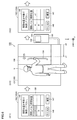
- FIG. 4 is a diagram showing the opening operation of the door 136 in chronological order.
- step S4 it is assumed that the user U switches the operation mode of the machine tool 100 to the automatic opening / closing mode (second mode) and opens the door 136 with respect to the operation panel 140. Based on this, in step S5, the control device 40 of the machine tool 100 controls the drive mechanism 137 and drives the door 136 to the set position “x1” stored in step S3.
- the machine tool 100 has a teaching function that allows the opening / closing position of the door 136 to be manually specified. Since the user can actually move the door 136 to set the opening / closing position, the user can set the opening / closing position while visually checking the degree of opening / closing. Further, since the user can set the opening / closing position only by moving the door 136, it is not necessary to rewrite the program or the opening / closing setting, and the opening / closing position of the door 136 can be easily set.
- the teaching function as described above does not exclude the function of changing the opening / closing position by rewriting the program or opening / closing setting. That is, the machine tool 100 may have a function of changing the opening / closing position of the door 136 in response to a change in the program or the opening / closing setting, in addition to the teaching function described above.
- step S1 of FIG. 3 a process for prompting the user U to manually move the door 136 (that is, a manual request process) is executed, but the manual request process is not necessarily executed. There is no need to.
- the machine tool 100 receives the position determination instruction of the door 136 at an arbitrary timing.
- the user manually or automatically moves the door 136 to an arbitrary position in order to change the degree of opening, and the machine tool 100 gives an instruction to determine the position of the door 136 during the operation in which the user is moving the door 136. Accept.
- the machine tool 100 acquires the actual position of the door 136 from the above-mentioned detection unit 138, and stores the acquired actual position as the opening position of the door 136 that opens the opening.
- the "opening position” means the opening / closing position of the door 136 when the opening instruction of the door 136 is received from the user.
- the machine tool 100 receives an instruction to open the door 136 (for example, an operation to open the door 136 with respect to the operation panel 140) so that the door 136 is positioned at the opening position stored in the teaching process. Controls the drive mechanism 137.
- FIG. 5 is a diagram showing an example of the device configuration of the machine tool 100.
- the machine tool 100 includes a control device 40, a door 136, a drive mechanism 137, and a detection unit 138.
- control device 40 as used herein means a device that controls the machine tool 100.
- the device configuration of the control device 40 is arbitrary.
- the control device 40 may be composed of a single control unit or a plurality of control units.
- the control device 40 is composed of a CPU unit 50 as a PLC (Programmable Logic Controller), a CNC unit 51, and an I / O (Input Output) unit 52. These units are connected to the fieldbus B and communicate with each other via the fieldbus B.
- the CPU unit 50 controls various units constituting the machine tool 100 according to a control program prepared in advance.
- the control program is described by, for example, a ladder program.
- the CNC unit 51 starts executing the machining program prepared in advance based on the machining start command received from the CPU unit 50.
- the machining program is described by, for example, an NC (Numerical Control) program. Further, the CNC unit 51 outputs to the CPU unit 50 the progress status of machining indicating that machining is stopped, machining is being executed, machining is completed, or the like.
- the I / O unit 52 is an interface for connecting various input / output devices.
- the drive mechanism 137 is connected to the I / O unit 52.
- the CPU unit 50 sends a control command to the drive mechanism 137 via the I / O unit 52.
- the drive mechanism 137 includes a servo driver 61 and a servomotor 62.
- the servo driver 61 sequentially receives input of the target opening / closing position from the CPU unit 50 and controls the servomotor 62.
- the servomotor 62 drives the door 136 via a ball screw (not shown), and drives the door 136 to an arbitrary opening / closing position in the X-axis direction.
- the servo driver 61 calculates the actual opening / closing position of the door 136 based on the feedback signal from the detection unit 138 for detecting the rotation angle of the servo motor 62.
- the detection unit 138 is, for example, an encoder.
- the servo driver 61 rotates and drives the servomotor 62 so that the door 136 moves to the negative side.
- the servo driver 61 rotates and drives the servomotor 62 so that the door 136 moves to the positive side.
- the servo driver 61 brings the actual opening / closing position of the servomotor 62 closer to the target opening / closing position while sequentially receiving feedback of the actual opening / closing position of the servomotor 62.
- the servo driver 61 drives the door 136 at an arbitrary position in the X-axis direction.
- FIGS. 6 to 10. 6 and 7 are diagrams showing the teaching process according to the first modification in chronological order.
- the user could only specify one opening / closing position of the door 136.
- the user in the teaching function according to the first modification, can set a plurality of opening / closing positions of the door 136 for each opening / closing level.
- step S11 it is assumed that the user U switches the operation mode of the machine tool 100 to the teaching mode. Based on this, the control device 40 of the machine tool 100 displays the opening / closing position setting screen 143A on the display 142.
- the setting screen 143A has a setting field 150.
- the open / close levels that can be set are displayed in a list.
- the opening / closing levels “A” to “C” are displayed in the setting field 150.
- the name of the open / close level can be changed arbitrarily by the user.
- the user can select the opening / closing level to be set from the displayed opening / closing levels "A" to "C". In step S11, for example, it is assumed that the opening / closing level "A" is selected.
- step S12 the user U grabs the handle 139, moves the door 136, and stops the door 136 at an arbitrary position in the X-axis direction.
- the user U moves the door 136 from the opening / closing position “x0” and stops the door 136 at the opening / closing position “x1”.
- step S13 it is assumed that the user U presses the confirmation button 147 on the setting screen 143A. Based on this, the control device 40 acquires the actual position of the door 136 from the above-mentioned detection unit 138 (see FIG. 2). After that, the control device 40 stores the acquired actual position in association with the currently selected open / close level. In the example of FIG. 6, the set position “x1” is stored in association with the open / close level “A”.
- the control device 40 displays the actual position of the door 136 acquired from the detection unit 138 in the open / close position column corresponding to the selected open / close level “A” in real time until the confirmation button 147 is pressed. Then, after the confirmation button 147 is pressed, the control device 40 stops the real-time display of the opening / closing position, and fixedly displays the actual position of the door 136 acquired from the detection unit 138 at the timing when the confirmation button 147 is pressed.
- step S14 it is assumed that the user U selects the opening / closing level "B" in the setting screen 143A. As a result, the machine tool 100 is in a state of accepting the opening / closing position for the opening / closing level “B”.
- step S15 the handle 139 is grasped, the door 136 is moved, and the door 136 is stopped at an arbitrary position in the X-axis direction.
- the user U stops the door 136 at the opening / closing position “x2”.
- step S16 it is assumed that the user U presses the confirmation button 147 on the setting screen 143A. Based on this, the control device 40 acquires the actual position of the door 136 from the above-mentioned detection unit 138 (see FIG. 2). After that, the control device 40 stores the acquired actual position in association with the currently selected open / close level “B”.
- the control device 40 prompts the user U to move the door 136 according to the opening / closing level. In response to this, the user U moves the door 136 according to the opening / closing level. Then, the control device 40 sequentially receives the position determination instruction from the user U for each opening / closing level, and stores the opening / closing position of the door 136 designated by the user U as a set position for each opening / closing level.
- FIG. 8 is a diagram showing an opening / closing setting 124 stored as a result of the teaching process.
- the open / close setting 124 is associated with the open / close positions set in the teaching mode for each open / close level.
- the open / close setting 124 may be stored in a memory in the machine tool 100, or may be stored in a memory in an external device such as a server.
- FIG. 9 is a diagram showing an operation mode of the door 136 at the opening / closing level “A”.
- the control device 40 displays the opening / closing operation screen 144 on the display 142 based on the operation of switching the operation mode of the machine tool 100 to the automatic opening / closing mode with respect to the operation panel 140.
- the open / close operation screen 144 includes, for example, open buttons 152A to 152C, a close button 153, and a cancel button 154.
- the number of open buttons displayed on the open / close operation screen 144 is the same as the number of open / close levels for which the open / close position is set during the teaching process.
- the three open buttons 152A to 152C are displayed on the opening / closing operation screen 144.
- the names representing the open buttons 152A to 152C are the same as the names of the open / close levels displayed during the teaching process.
- the open button 152A represents the open / close level “A”.
- the open button 152B represents the open / close level “B”.
- the open button 152C represents an open / close level “C”.
- the control device 40 acquires the opening / closing position “x1” corresponding to the opening / closing level “A” with reference to the opening / closing setting 124 (see FIG. 8) described above. After that, the control device 40 controls the drive mechanism 137 and drives the door 136 to the opening / closing position “x1”.
- FIG. 10 is a diagram showing an operation mode of the door 136 at the opening / closing level “B”. As shown in FIG. 10, it is assumed that the user presses the open button 152B. Based on this, the control device 40 acquires the opening / closing position “x2” corresponding to the opening / closing level “B” with reference to the opening / closing setting 124 (see FIG. 8) described above. After that, the control device 40 controls the drive mechanism 137 and drives the door 136 to the opening / closing position “x2”.
- the control device 40 controls the drive mechanism 137 and closes the door 136.
- the control device 40 closes the open / close operation screen 144 and ends the automatic open / close mode.
- the control device 40 drives the door 136 to the set position corresponding to the input opening / closing level based on the reception of the opening / closing level input as the opening / closing instruction from the user. Since the user can set the opening / closing position for a plurality of opening / closing levels, the opening / closing degree can be changed according to the application.
- the number of opening / closing levels at which the opening / closing position can be set was constant.
- the number of open / close levels that can set the open / close position can be arbitrarily changed.
- FIG. 11 is a diagram showing a screen transition of the setting screen 143B when the opening / closing level at which the opening / closing position can be set is increased.
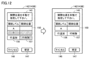
- FIG. 12 is a diagram showing a screen transition of the setting screen 143B when the opening / closing level at which the opening / closing position can be set is reduced.
- the setting screen 143B shown in FIGS. 11 and 12 is displayed on the setting screen 143B and an additional button 156 (first reception unit) that receives an instruction to increase the number of open / close level displays displayed on the setting screen 143B by a predetermined number. It includes a delete button 157 (second reception unit) that receives an instruction to reduce the number of displayed opening / closing levels by a predetermined number. Since other points are the same as the setting screen 143A shown in FIG. 6 above, the description thereof will not be repeated below.
- a line including an open / close level display field and an open / close position display field is added to the setting field 150.
- a line of opening / closing level “C” is added.
- the number of additional opening / closing levels by pressing the additional button 156 does not necessarily have to be one.
- the control device 40 may increase the opening / closing level display by two or more based on the additional button 156 being pressed.
- the means for increasing the number of open / close level displays is not limited to the additional button 156, and the open / close level display can be added by various means.
- the increase in the number of open / close level displays may be realized by voice input.
- the delete button 157 when the user presses the delete button 157, the line selected in the setting field 150 is deleted.
- the delete button 157 is pressed with the open / close level “B” row selected, thereby deleting the open / close level “B” row.
- the number of open / close level deletions by pressing the delete button 157 does not necessarily have to be one.
- the control device 40 may reduce two or more open / close level indications based on the press of the delete button 157.
- the means for reducing the number of open / close level displays is not limited to the delete button 157, and the open / close level display can be deleted by various methods.
- the reduction in the number of open / close level displays may be realized by voice input.
- the user can set the opening / closing position of the door 136 for each of the opening / closing levels displayed on the setting screen 143B.
- the user can arbitrarily change the number of opening / closing levels for setting the opening / closing position.
- the user can set the opening / closing position according to various uses, and can change the opening / closing setting of the door 136 more flexibly.
- FIG. 13 is a diagram showing the teaching process according to the modified example 3 in chronological order.
- the user set the opening / closing position by manually moving the door 136.
- the user can set the opening / closing position by automatically moving the door 136.
- the automatic drive of the door 136 is realized by the drive mechanism 137 (see FIG. 2) described above.
- step S21 it is assumed that the user has switched the operation mode of the machine tool 100 to the teaching mode. Based on this, the control device 40 of the machine tool 100 displays the opening / closing position setting screen 143C on the display 142.
- the setting screen 143C further includes the manual button 160, the automatic button 161, the open button 162, the close button 163, and the open / close position display area 165, and is the above-mentioned setting screen 143A (see FIG. 7). Is different. In the following, the same matters as the above-mentioned setting screen 143A will not be repeated.
- the teaching mode in this modification has the above-mentioned manual teaching mode in which the opening / closing position of the door 136 is manually specified, and the automatic teaching mode in which the opening / closing position of the door 136 is automatically specified by using the drive mechanism 137.
- the teaching mode is switched to the manual teaching mode.
- the automatic button 161 the teaching mode is switched to the automatic teaching mode.
- One of the manual button 160 and the automatic button 161 can be selected. That is, when the manual button 160 is pressed, the manual button 160 is selected and the automatic button 161 is not selected. On the other hand, when the automatic button 161 is pressed, the automatic button 161 is selected and the manual button 160 is not selected. In the example of FIG. 13, the automatic button 161 is selected, and the automatic teaching mode is selected.
- the control device 40 changes the content of the message 145 according to the current teaching mode. More specifically, when the current teaching mode is the manual teaching mode, the control device 40 displays a message urging the user to manually move the door 136. On the other hand, when the current teaching mode is the automatic teaching mode, the control device 40 displays a message urging the user to automatically move the door 136.
- the control device 40 continues the opening operation of the door 136 at a low speed while the open button 162 is pressed, and the door is not pressed based on the fact that the open button 162 is not pressed.
- the opening operation of 136 is stopped.
- the control device 40 continues the closing operation of the door 136 at a low speed while the closing button 163 is being pressed, and the door 136 is closed based on the fact that the closing button 163 is not pressed. Stop operation.
- the user can arbitrarily specify the opening / closing position without manually moving the door 136.
- the open / close position display area 165 displays the current open / close position of the door 136.
- the opening / closing position is indicated by, for example, the degree of opening of the door 136 based on the state in which the door 136 is completely closed (for example, 0 mm).
- the unit of the opening / closing position is, for example, "mm”.
- the opening / closing position displayed in the opening / closing position display area 165 is linked with the opening / closing operation of the door 136. As a result, the user can numerically recognize the current open / close position in real time.
- step S22 it is assumed that the user moves the door 136 from the opening / closing position "x0" and stops the door 136 at the opening / closing position "x1" by operating the open button 162 and the close button 163.
- step S23 it is assumed that the user presses the confirmation button 147 on the setting screen 143C. Based on this, the control device 40 acquires the actual position of the door 136 from the above-mentioned detection unit 138 (see FIG. 2). After that, the control device 40 stores the acquired actual position in association with the currently selected open / close level. In the example of FIG. 13, the set position “x1” is stored in association with the open / close level “A”. By repeating the above processing, the user sequentially sets the opening / closing position for each opening / closing level.
- the machine tool 100 may include at least one of a manual teaching mode and an automatic teaching mode.
- FIG. 14 is a diagram showing a setting screen 143D according to the modified example 4.
- the setting screen 143D is displayed on the display 142 of the operation panel 140, for example.
- the operation panel 140 accepts various operations on the door 136 (for example, opening operation of the door 136, closing operation of the door 136, positioning operation of the door 136, etc.) via the setting screen 143D.
- the setting screen 143D includes a teaching enable button 170, a low speed open button 171, a low speed close button 172, a teaching execution button 173, an open button 176, a close button 177, and an unlock button 178. , Includes a door designation button 179.
- the teaching enable button 170 is a button for switching the operation mode. Each time the user presses the teaching enable button 170, the state of the teaching enable button 170 alternates between the selected state and the non-selected state. Based on the teaching enable button 170 changing from the non-selected state to the selected state, the machine tool 100 switches the current operation mode to the teaching mode described above.
- the teaching mode is an operation mode capable of accepting the setting of the open position of the door 136. Based on the teaching enable button 170 changing from the selected state to the non-selected state, the machine tool 100 switches the operation mode from the teaching mode to the above-mentioned automatic opening / closing mode.
- the automatic opening / closing mode is an operation mode in which the door 136 can be opened at the set open position.
- the machine tool 100 may turn on a lamp (not shown) provided on the machine tool 100. As a result, the user can easily recognize that the current operation mode is the teaching mode.
- the machine tool 100 turns off the lamp based on the teaching enable button 170 changing from the selected state to the non-selected state.
- the machine tool 100 may turn off the lamp based on the completion of teaching at the open position of the door 136.
- the teaching enable button 170 is configured so that it can be operated only by a user to whom a predetermined access authority is given.
- the access authority is specified from, for example, login information to the machine tool 100.
- the low-speed open button 171 is a button for accepting the opening operation (first opening operation) of the door 136 in the teaching mode.
- the control device 40 of the machine tool 100 controls the drive mechanism 137 (see FIG. 2) described above, and starts the opening operation of the door 136.
- the control device 40 continues the opening operation of the door 136 while the low-speed open button 171 is pressed, and based on the fact that the low-speed open button 171 is not pressed, the door 136 is opened.
- the opening speed of the door 136 in the teaching mode is slower than the opening speed of the door 136 in the automatic opening / closing mode. That is, the opening speed of the door 136 using the low-speed open button 171 is slower than the opening speed of the door 136 using the open button 176 described later.
- the low speed closing button 172 is a button for accepting the closing operation of the door 136 in the teaching mode.
- the control device 40 of the machine tool 100 controls the drive mechanism 137 described above to start closing the door 136.
- the control device 40 continues the closing operation of the door 136 at a low speed while the low speed closing button 172 is pressed, and based on the fact that the low speed closing button 172 is not pressed, the door 136 Stop the closing operation.
- the closing speed of the door 136 in the teaching mode is slower than the closing speed of the door 136 in the automatic opening / closing mode. That is, the closing speed of the door 136 using the low-speed closing button 172 is slower than the closing speed of the door 136 using the closing button 177 described later.
- the teaching execution button 173 is a button for accepting the position determination operation of the door 136. After the open position of the door 136 is adjusted by the low-speed open button 171 and the low-speed close button 172, when the teaching execution button 173 is pressed while the teaching enable button 170 is selected, the control device 40 of the machine tool 100 changes. , The actual position of the door 136 is acquired from the above-mentioned detection unit 138 (see FIG. 2). After that, the control device 40 stores the acquired actual position as the open position of the door 136 in the open / close setting 124.
- the teaching execution button 173 is configured so that it can be operated only by a user to whom a predetermined access authority is given.
- the access authority is specified from, for example, login information to the machine tool 100.
- the open button 176 is a button for accepting the opening operation (second opening operation) of the door 136 in the automatic opening / closing mode.
- the control device 40 of the machine tool 100 controls the drive mechanism 137 described above, and the drive mechanism 137 (see FIG. 2) is set so that the door 136 is located at the set open position. Control.
- the opening speed of the door 136 using the open button 176 is faster than the opening speed of the door 136 using the low speed open button 171.
- the close button 177 is a button for accepting the closing operation of the door 136 in the automatic opening / closing mode.
- the control device 40 of the machine tool 100 controls the drive mechanism 137 (see FIG. 2) so that the door 136 is located at a predetermined closed position.
- the closing speed of the door 136 using the close button 177 is faster than the closing speed of the door 136 using the low speed close button 172.
- the unlock button 178 is a button for unlocking the door 136.
- the machine tool 100 stops supplying electric power to the drive mechanism 137. More specifically, when electric power is supplied from the power source to the drive mechanism 137, the driving force of the drive mechanism 137 acts on the door 136. On the other hand, when power is not supplied from the power source to the drive mechanism 137, the driving force of the drive mechanism 137 does not act on the door 136.
- the control device 40 stops the supply of electric power from the power source to the drive mechanism 137 based on the release button 178 being pressed. As a result, the driving force is not applied to the door 136, and the user can manually move the door 136. As a result, the user can manually fine-tune the position of the door 136.
- the machine tool 100 may be composed of two or more doors 136. That is, the door 136 may be composed of two left and right doors, two upper and lower doors, or four upper, lower, left and right doors.
- the drive mechanism 137 (see FIG. 2) and the detection unit 138 (see FIG. 2) described above are provided according to the number of doors 136, and the machine tool 100 is configured to accept the setting of the open position of each door. Will be done.
- the designated operation of the door 136 to be driven is accepted by, for example, the door designation button 179.
- the door designation button 179 is, for example, a button 179A for designating the left door, a button 179B for designating the right door, a button 179C for designating the upper door, and a button 179D for designating the lower door. And include. The user can select one of the buttons 179A-179D. When the selected button is pressed again, none of the buttons 179A to 179D is selected.
- buttons 179A and 179B are selected, the left door of the machine tool 100 is selected as the drive target.
- button 179B is selected, the right door of the machine tool 100 is selected as the drive target.
- button 179C is selected, the upper door of the machine tool 100 is selected as the drive target.
- button 179D is selected, the lower door of the machine tool 100 is selected as the drive target.
- the control device 40 of the machine tool 100 starts the opening operation of the door selected as the drive target by the door designation button 179. Then, the control device 40 continues the opening operation of the door to be driven at a low speed while the low-speed open button 171 is pressed, and the control device 40 is in a state where the low-speed open button 171 is not pressed. Stop the door opening operation. After that, when the teaching execution button 173 is pressed, the control device 40 acquires the actual position of the door 136 to be driven from the above-mentioned detection unit 138 (see FIG. 2), and uses the actual position as the identification information of the door to be driven. Is stored in the open / close setting 124 in association with.
- the machine tool 100 When the low-speed open button 171 is pressed while none of the buttons 179A to 179D is selected, the machine tool 100 simultaneously opens all the doors that can be designated as drive targets at low speed.
- the control device 40 of the machine tool 100 starts the closing operation of the door selected as the driving target by the door designation button 179. Then, the control device 40 continues the closing operation of the door to be driven at a low speed while the low speed closing button 172 is pressed, and the control device 40 is in a state where the low speed closing button 172 is not pressed. Stop the closing operation of the door.
- the machine tool 100 When the low-speed closing button 172 is pressed while none of the buttons 179A to 179D is selected, the machine tool 100 simultaneously closes all the doors that can be designated as drive targets at low speed.
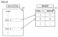
- FIG. 15 is a diagram showing a machining program 122 as an example.
- the machining program 122 includes various instruction codes related to machining of the workpiece.
- the machine tool 100 processes the work according to the processing program 122.
- the door is opened and closed during the machining process of the work.
- the machine tool 100 opens a door 136 before the work is carried into the machine tool 100 by the automatic transfer device.
- the automatic transfer device carries the work to be machined into the machine tool 100.
- the machine tool 100 closes the door 136 and starts machining the work.
- the door 136 is opened, and the automatic transfer device carries out the processed work from the machine tool 100. After that, the machine tool 100 closes the door 136.
- Such a machining process is realized by, for example, the machining program 122 shown in FIG.
- the machining program 122 is defined by, for example, a G code.
- the machining program 122 includes an instruction code "GXX" for instructing the opening operation of the door 136.
- "XX" is a predetermined constant. The user can specify the open / close level in the instruction code "GXX”.
- the machine tool 100 When the instruction code "GXX" is executed, the machine tool 100 specifies the opening level specified in the instruction code "GXX”, refers to the opening / closing setting 124, and refers to the opening / closing position corresponding to the opening / closing position. To get. Then, the machine tool 100 drives the door 136 to the acquired opening / closing position.
- FIG. 15 shows an example in which the instruction code for opening the door 136 is specified by the G code, but the instruction code does not necessarily have to be specified by the G code.
- the instruction code may be specified on the ladder program.
- the instruction code is defined in the control program 92 (see FIG. 17) on the CPU unit 50 (see FIG. 5) described above.
- the door opening command may be specified by the M code.
- the open instruction is specified by "M85".
- the machine tool 100 drives the door 136 to the set open position.
- the open position may be specified on the machining program 122, the ladder program (PLC program), or as a setting parameter referred to by the machining program 122 or the ladder program. ..
- PLC program ladder program
- Error code for example, EX6042
- the door 136 closing command may be specified by the G code or the M code.
- the door 136 closing order is specified in "M86".
- the machine tool 100 drives the door 136 to the set closed position.
- the closed position may be specified on the machining program 122, the ladder program (PLC program), or as a setting parameter referred to by the machining program 122 or the ladder program. ..
- the operation mode of the machine tool 100 includes a manual opening / closing mode in which the door 136 is manually opened and an automatic opening / closing mode in which the door 136 is automatically opened.
- the control device 40 of the machine tool 100 determines the opening / closing position of the door 136 from the above-mentioned detection unit 138 (see FIG. 2) each time the door 136 is manually opened. Acquire and store the opening / closing position. As an example, the open / close position is stored based on the fact that it does not change for a certain period of time or longer.
- FIG. 16 is a diagram showing a database 96 of open / close positions.
- the opening / closing time of the door 136 and the opening / closing position of the door 136 are associated with each other.
- the identification information (for example, identification) of the user who has performed the opening / closing operation is further associated.
- the user identification information is specified, for example, from the login information for the machine tool 100.
- the control device 40 automatically calculates the set position related to the opening / closing of the door 136 based on the opening / closing position stored in the database 96.
- the set position is equal to or greater than the minimum value of the open / close position stored in the database 96, and is equal to or less than the maximum value of the open / close position stored in the database 96.
- the set position is the average value of the open / close positions stored in the database 96. In another aspect, the set position is the median of the open / close positions stored in the database 96. In yet another aspect, the set position is the maximum or minimum value of the open / close position stored in the database 96.
- a plurality of the set positions may be calculated from the database 96.
- the set position is calculated for each user.
- the control device 40 controls the drive mechanism 137 so that the door 136 is located at the above-mentioned set position based on the reception of the instruction to open the door 136.
- the control device 40 automatically sets the optimum opening / closing position of the door 136 from the past operation history. At that time, the user only has to open and close the door 136 as usual, and as a result, the opening / closing position of the door 136 can be easily set.
- FIG. 17 is a diagram showing an example of the hardware configuration of the CPU unit 50.
- the CPU unit 50 includes a processor 71, a ROM (Read Only Memory) 72, a RAM (Random Access Memory) 73, a communication interface 74, a fieldbus controller 75, and a storage device 90. These components are connected to the internal bus 79.
- the processor 71 is composed of, for example, at least one integrated circuit.
- An integrated circuit is composed of, for example, at least one CPU, at least one GPU (Graphics Processing Unit), at least one ASIC (Application Specific Integrated Circuit), at least one FPGA (Field Programmable Gate Array), or a combination thereof. Can be done.
- the processor 71 controls the operation of the CPU unit 50 by executing various programs such as the control program 92.
- the control program 92 defines instructions for controlling various devices in the machine tool 100.
- the processor 71 reads the control program 92 from the storage device 90 or the ROM 72 into the RAM 73 based on the reception of the execution instruction of the control program 92.
- the RAM 73 functions as a working memory and temporarily stores various data necessary for executing the control program 92.
- a LAN Local Area Network
- an antenna or the like is connected to the communication interface 74.
- the CPU unit 50 exchanges data with an external device (for example, a server) via the communication interface 74.
- the CPU unit 50 may be configured so that the control program 92 can be downloaded from the external device.
- the fieldbus controller 75 is an interface for realizing communication with various units connected to the fieldbus. Examples of the unit connected to the fieldbus include a CNC unit 51 and an I / O unit 52.
- the storage device 90 is, for example, a storage medium such as a hard disk or a flash memory.
- the storage device 90 stores the control program 92, the above-mentioned database 96 (see FIG. 16), the above-mentioned open / close setting 124 (see FIG. 8), and the like. These storage locations are not limited to the storage device 90, and may be stored in a storage area (for example, cache memory) of the processor 71, a ROM 72, a RAM 73, an external device (for example, a server), or the like.
- the control program 92 may be provided by being incorporated into a part of an arbitrary program, not as a single program. In this case, various processes according to the present embodiment are realized in cooperation with an arbitrary program. Even a program that does not include such a part of modules does not deviate from the purpose of the control program 92 according to the present embodiment. Further, some or all of the functions provided by the control program 92 may be realized by dedicated hardware. Further, the CPU unit 50 may be configured in the form of a so-called cloud service in which at least one server executes a part of the processing of the control program 92.
- FIG. 18 is a diagram showing an example of the hardware configuration of the machine tool 100.
- the machine tool 100 includes a CNC unit 51, servo drivers 111A to 111D, servomotors 112A to 112D, encoders 113A to 113D, ball screws 114A and 114B, and a spindle 115.
- the CNC unit 51 includes a processor 101, a ROM 102, a RAM 103, a communication interface 104, and an operation panel 140.
- the processor 101 is composed of at least one integrated circuit.
- An integrated circuit is composed of, for example, at least one CPU, at least one MPU, at least one ASIC, at least one FPGA, or a combination thereof.
- the processor 101 controls the operation of the CNC unit 51 by executing various programs such as the machining program 122.
- the machining program 122 defines various instructions for realizing machining of the workpiece.
- the processor 101 reads the machining program 122 from the storage device 120 into the ROM 102 based on the reception of the execution instruction of the machining program 122.
- the RAM 103 functions as a working memory and temporarily stores various data necessary for executing the machining program 122.
- the communication interface 104 is an interface for connecting to the field network NW (see FIG. 6).
- the CNC unit 51 exchanges data with various devices (for example, CPU unit 50, I / O unit 52, etc.) connected to the field network NW via the communication interface 104.
- the operation panel 140 accepts various operations on the machine tool 100. Further, the operation panel 140 includes a display 142 and displays various information.
- the display is, for example, a liquid crystal display, an organic EL display, or other display device.
- the CNC unit 51 controls the servo drivers 111A to 111D according to the machining program 122.
- the servo driver 111A moves the above-mentioned table 116 connected to the ball screw 114A in the X-axis direction (see FIG. 2) according to a control command from the CNC unit 51, and moves the table 116 to an arbitrary position in the X-axis direction. ..
- the servo driver 111B moves the table 116 connected to the ball screw 114B in the Y-axis direction (see FIG. 2) according to a control command from the CNC unit 51, and moves the table 116 to an arbitrary position in the Y-axis direction.
- the servo driver 111C moves the spindle 115 in the Z-axis direction (see FIG. 2) according to a control command from the CNC unit 51, and moves the spindle 115 to an arbitrary position in the Z-axis direction.
- the servo driver 111D controls the rotation speed of the spindle 115 according to a control command from the CNC unit 51.
- the storage device 120 is, for example, a storage medium such as a hard disk or a flash memory.
- the storage device 120 stores the machining program 122 and the like.
- the storage location of the processing program 122 is not limited to the storage device 120, and may be stored in a storage area of the processor 101 (for example, a cache area), a ROM 102, a RAM 103, an external device (for example, a server), or the like.
- the machining program 122 may be provided by being incorporated into a part of an arbitrary program, not as a single program. In this case, various processes according to the present embodiment are realized in cooperation with an arbitrary program. Even a program that does not include such a part of the modules does not deviate from the purpose of the machining program 122 according to the present embodiment. Further, some or all of the functions provided by the machining program 122 may be realized by dedicated hardware. Further, the CNC unit 51 may be configured in the form of a so-called cloud service in which at least one server executes a part of the processing of the machining program 122.
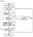
- FIG. 19 is a flowchart showing the flow of the teaching process. The process shown in FIG. 19 is executed, for example, by the control device 40 of the machine tool 100.
- step S110 the control device 40 determines whether or not the operation mode of the machine tool 100 has been switched to the teaching mode by the user operation on the operation panel 140.
- the control device 40 determines that the operation mode of the machine tool 100 has been switched to the teaching mode (YES in step S110)
- the control device 40 switches the control to step S112. If not (NO in step S110), the control device 40 closes the setting screen 143B and ends the teaching process shown in FIG.
- step S112 the control device 40 executes a process of urging the user to move the door 136.
- the control device 40 displays the above-mentioned setting screen 143B (see FIG. 11) on the display 142. As a result, the user is prompted to display the setting screen 143B and manually moves the door 136.
- step S120 the control device 40 determines whether or not the position determination instruction of the door 136 has been received.
- the control device 40 receives a position confirmation instruction of the door 136 based on the user pressing the confirmation button 147 on the setting screen 143B.
- the control device 40 switches the control to step S124. If not (NO in step S120), the control device 40 switches control to step S122.
- step S122 the control device 40 determines whether or not the cancellation instruction has been accepted.
- the control device 40 receives a cancel instruction based on the user pressing the cancel button 146 on the setting screen 143B.
- the control device 40 closes the setting screen 143B and ends the process in FIG. If not (NO in step S122), the controller 40 returns control to step S120.
- step S124 the control device 40 acquires the current open / close position of the door 136 from the above-mentioned detection unit 138. After that, the control device 40 stores the acquired open / close position in the open / close setting 124 (see FIG. 8) described above in association with the open / close level selected on the setting screen 143B.
- step S130 the control device 40 determines whether or not the instruction to end the teaching mode has been received.
- the termination instruction is issued, for example, based on the user pressing the cancel button 146 on the setting screen 143B.
- the control device 40 closes the setting screen 143B and ends the process in FIG. If not (NO in step S130), the controller 40 returns control to step S112.
- step S112 the above-mentioned setting screen 143C (see FIG. 13) is displayed. More specifically, in step S112, when the manual button 160 on the setting screen 143C is pressed, the control device 40 prompts the user to manually move the door 136. Alternatively, when the automatic button 161 of the setting screen 143C is pressed, the control device 40 prompts the user to automatically move the door 136 (by motor drive).
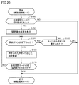
- FIG. 20 is a flowchart showing the flow of the automatic opening / closing process of the door 136.
- the process shown in FIG. 20 is executed, for example, by the control device 40 of the machine tool 100.
- step S150 the control device 40 determines whether or not the operation mode of the machine tool 100 has been switched to the automatic opening / closing mode by the user operation on the operation panel 140.
- the control device 40 determines that the operation mode of the machine tool 100 has been switched to the automatic opening / closing mode (YES in step S150)
- the control device 40 switches the control to step S152. If not (NO in step S150), the control device 40 closes the open / close operation screen 144 and ends the process in FIG.
- step S152 the control device 40 displays the above-mentioned opening / closing operation screen 144 (see FIG. 9) on the display 142.
- step S160 the control device 40 determines whether or not the open / close button displayed on the open / close operation screen 144 has been pressed.
- the control device 40 determines that the open / close button displayed on the open / close operation screen 144 has been pressed (YES in step S160)
- the control device 40 switches the control to step S164. If not (NO in step S160), the control device 40 switches control to step S162.
- step S162 the control device 40 determines whether or not the cancel button 154 displayed on the open / close operation screen 144 has been pressed. When the control device 40 determines that the cancel button 154 has been pressed (YES in step S162), the control device 40 closes the open / close operation screen 144 and ends the process in FIG. If not (NO in step S162), the controller 40 returns control to step S160.
- step S164 the control device 40 drives the door 136 according to the type of the open / close button pressed in step S160.
- the control device 40 specifies the open / close level corresponding to the pressed open button. Then, the control device 40 acquires the opening / closing position corresponding to the specified opening / closing level with reference to the opening / closing setting 124 (see FIG. 8) described above. After that, the control device 40 controls the drive mechanism 137 and drives the door 136 to the acquired opening / closing position.
- the close button 153 displayed on the open / close operation screen 144 is pressed, the control device 40 controls the drive mechanism 137 and drives the door 136 to a predetermined closed position.
- step S170 the control device 40 determines whether or not the end instruction of the automatic opening / closing mode has been received.
- the end instruction is issued, for example, based on the user pressing the cancel button 154 on the open / close operation screen 144.
- the control device 40 closes the open / close operation screen 144 and ends the process in FIG. If not (NO in step S170), the controller 40 returns control to step S160.
- the machine tool 100 has a teaching function capable of manually designating the opening / closing position of the door 136. Since the user can actually move the door 136 to set the opening / closing position, the user can set the opening / closing position while visually checking the degree of opening / closing. Further, since the user can set the opening / closing position only by moving the door 136, it is not necessary to rewrite the program or the opening / closing setting, and the opening / closing position of the door 136 can be easily set.
- 40 control device 50 CPU unit, 51 CNC unit, 52 I / O unit, 61, 111A to 111D servo driver, 62, 112A to 112D servo motor, 71, 101 processor, 72, 102 ROM, 73, 103 RAM, 74 , 104 communication interface, 75 field bus controller, 79 internal bus, 90, 120 storage device, 92 control program, 96 database, 100 machine tool, 113A-113D encoder, 114A, 114B ball screw, 115 spindle, 116 table, 122 machining Program, 124 open / close setting, 131 cover, 132 opening, 136 door, 137 drive mechanism, 138 detector, 139 handle, 140 operation panel, 142 display, 143, 143A to 143D setting screen, 144 open / close operation screen, 145 message, 146 , 154 Cancel button, 147 Confirm button, 150 Setting field, 152A-152C, 162 Open button, 153, 163 Close button, 156 Add button,
Landscapes
- Engineering & Computer Science (AREA)
- Human Computer Interaction (AREA)
- Manufacturing & Machinery (AREA)
- Physics & Mathematics (AREA)
- General Physics & Mathematics (AREA)
- Automation & Control Theory (AREA)
- Auxiliary Devices For Machine Tools (AREA)
- Machine Tool Sensing Apparatuses (AREA)
- Numerical Control (AREA)
Priority Applications (4)
| Application Number | Priority Date | Filing Date | Title |
|---|---|---|---|
| JP2021528244A JP7439082B2 (ja) | 2019-06-21 | 2020-06-16 | 工作機械、工作機械の制御方法、および、工作機械の制御プログラム |
| EP20825683.4A EP3974102A4 (de) | 2019-06-21 | 2020-06-16 | Werkzeugmaschine, werkzeugmaschinensteuerungsverfahren und werkzeugmaschinensteuerungsprogramm |
| CN202080045394.6A CN113994280B (zh) | 2019-06-21 | 2020-06-16 | 机床、机床的控制方法以及计算机可读存储介质 |
| US17/621,215 US11754993B2 (en) | 2019-06-21 | 2020-06-16 | Machine tool, control method for machine tool, and control program for machine tool |
Applications Claiming Priority (4)
| Application Number | Priority Date | Filing Date | Title |
|---|---|---|---|
| JP2019115545 | 2019-06-21 | ||
| JP2019-115545 | 2019-06-21 | ||
| JP2019182107A JP6777800B1 (ja) | 2019-06-21 | 2019-10-02 | 工作機械、工作機械の制御方法、および、工作機械の制御プログラム |
| JP2019-182107 | 2019-10-02 |
Publications (1)
| Publication Number | Publication Date |
|---|---|
| WO2020255941A1 true WO2020255941A1 (ja) | 2020-12-24 |
Family
ID=72938161
Family Applications (1)
| Application Number | Title | Priority Date | Filing Date |
|---|---|---|---|
| PCT/JP2020/023508 Ceased WO2020255941A1 (ja) | 2019-06-21 | 2020-06-16 | 工作機械、工作機械の制御方法、および、工作機械の制御プログラム |
Country Status (5)
| Country | Link |
|---|---|
| US (1) | US11754993B2 (de) |
| EP (1) | EP3974102A4 (de) |
| JP (2) | JP6777800B1 (de) |
| CN (1) | CN113994280B (de) |
| WO (1) | WO2020255941A1 (de) |
Families Citing this family (3)
| Publication number | Priority date | Publication date | Assignee | Title |
|---|---|---|---|---|
| US20230259376A1 (en) * | 2022-02-04 | 2023-08-17 | Intelligent Entry Machines LLC | Gate Operator with Context Sensitive QR Code |
| WO2026004086A1 (ja) * | 2024-06-28 | 2026-01-02 | 株式会社Fuji | 工作機械 |
| JP7742513B1 (ja) * | 2025-06-06 | 2025-09-19 | Dmg森精機株式会社 | 工作機械および工作機械のドア制御方法 |
Citations (7)
| Publication number | Priority date | Publication date | Assignee | Title |
|---|---|---|---|---|
| JPS58101982A (ja) * | 1981-12-14 | 1983-06-17 | 株式会社ナブコ | 自動扉の開閉制御方法 |
| JPH07304358A (ja) * | 1994-05-10 | 1995-11-21 | Nissan Motor Co Ltd | オートドライビングポジション制御装置 |
| JP2006075916A (ja) * | 2004-09-07 | 2006-03-23 | Okuma Corp | 工作機械の保護カバー開閉装置 |
| JP2009214214A (ja) | 2008-03-10 | 2009-09-24 | Brother Ind Ltd | 工作機械の扉装置 |
| JP2010228063A (ja) * | 2009-03-27 | 2010-10-14 | Makino Milling Mach Co Ltd | 工具交換装置 |
| JP2017164868A (ja) * | 2016-03-17 | 2017-09-21 | ファナック株式会社 | 工作機械システムおよび開停止位置算出装置 |
| JP2017185584A (ja) * | 2016-04-05 | 2017-10-12 | ファナック株式会社 | 工作機械システム |
Family Cites Families (7)
| Publication number | Priority date | Publication date | Assignee | Title |
|---|---|---|---|---|
| JPH1193520A (ja) * | 1997-09-19 | 1999-04-06 | Toyota Auto Body Co Ltd | 自動ドアの開閉制御方法 |
| JP4215714B2 (ja) * | 2004-12-28 | 2009-01-28 | 三井金属鉱業株式会社 | ドア開閉装置 |
| JP4966670B2 (ja) * | 2007-01-11 | 2012-07-04 | 株式会社森精機製作所 | 工作機械 |
| JP4971214B2 (ja) * | 2008-02-07 | 2012-07-11 | アスモ株式会社 | 開閉部材制御装置及び開閉装置 |
| JP2009256906A (ja) * | 2008-04-14 | 2009-11-05 | Asmo Co Ltd | 開閉部材制御装置及び開閉装置 |
| JP6316644B2 (ja) * | 2014-04-23 | 2018-04-25 | ファナック株式会社 | 扉の速度を制御可能なシステム |
| JP6306551B2 (ja) * | 2015-10-01 | 2018-04-04 | ファナック株式会社 | 開閉速度を変更可能なドアを有する加工機械 |
-
2019
- 2019-10-02 JP JP2019182107A patent/JP6777800B1/ja active Active
-
2020
- 2020-06-16 CN CN202080045394.6A patent/CN113994280B/zh active Active
- 2020-06-16 US US17/621,215 patent/US11754993B2/en active Active
- 2020-06-16 EP EP20825683.4A patent/EP3974102A4/de active Pending
- 2020-06-16 WO PCT/JP2020/023508 patent/WO2020255941A1/ja not_active Ceased
- 2020-06-16 JP JP2021528244A patent/JP7439082B2/ja active Active
Patent Citations (7)
| Publication number | Priority date | Publication date | Assignee | Title |
|---|---|---|---|---|
| JPS58101982A (ja) * | 1981-12-14 | 1983-06-17 | 株式会社ナブコ | 自動扉の開閉制御方法 |
| JPH07304358A (ja) * | 1994-05-10 | 1995-11-21 | Nissan Motor Co Ltd | オートドライビングポジション制御装置 |
| JP2006075916A (ja) * | 2004-09-07 | 2006-03-23 | Okuma Corp | 工作機械の保護カバー開閉装置 |
| JP2009214214A (ja) | 2008-03-10 | 2009-09-24 | Brother Ind Ltd | 工作機械の扉装置 |
| JP2010228063A (ja) * | 2009-03-27 | 2010-10-14 | Makino Milling Mach Co Ltd | 工具交換装置 |
| JP2017164868A (ja) * | 2016-03-17 | 2017-09-21 | ファナック株式会社 | 工作機械システムおよび開停止位置算出装置 |
| JP2017185584A (ja) * | 2016-04-05 | 2017-10-12 | ファナック株式会社 | 工作機械システム |
Also Published As
| Publication number | Publication date |
|---|---|
| EP3974102A4 (de) | 2023-07-12 |
| CN113994280A (zh) | 2022-01-28 |
| EP3974102A1 (de) | 2022-03-30 |
| JP2021000718A (ja) | 2021-01-07 |
| JP7439082B2 (ja) | 2024-02-27 |
| US11754993B2 (en) | 2023-09-12 |
| CN113994280B (zh) | 2024-09-20 |
| JPWO2020255941A1 (de) | 2020-12-24 |
| JP6777800B1 (ja) | 2020-10-28 |
| US20220236715A1 (en) | 2022-07-28 |
Similar Documents
| Publication | Publication Date | Title |
|---|---|---|
| CN104932419B (zh) | 使用手动操作工作机械的模拟装置 | |
| JP5766762B2 (ja) | 動作設定画面を備えた数値制御装置 | |
| US7848851B2 (en) | Controller of work piece-conveying robot | |
| JP7439082B2 (ja) | 工作機械、工作機械の制御方法、および、工作機械の制御プログラム | |
| US5418729A (en) | Communication linkage system for programmable band saw | |
| WO2020012547A1 (ja) | 数値制御装置 | |
| US20090037025A1 (en) | Controller for robot having robot body and additional mechanism providing additional operation axes | |
| JP2019185467A (ja) | 設定装置及び設定プログラム | |
| JP6966604B1 (ja) | 工作機械、工作機械の制御方法、および、工作機械の制御プログラム | |
| JP4606658B2 (ja) | 工作機械、その数値制御装置およびその制御方法 | |
| US20240377813A1 (en) | Numerical controller | |
| WO2023042249A1 (ja) | 工作機械、制御方法、および制御プログラム | |
| JPH11114756A (ja) | 工作機械 | |
| JP6887070B1 (ja) | 工作機械、表示制御方法、および表示制御プログラム | |
| US20060052900A1 (en) | Numerical control apparatus | |
| KR20110019813A (ko) | Cnc 공작기계의 atc 동작 정보 표시 방법 및 장치 | |
| JP2018124722A (ja) | 制御装置 | |
| KR101494130B1 (ko) | 인덱스 테이블의 제어장치 | |
| JP6900561B1 (ja) | 工作機械、情報処理方法、および情報処理プログラム | |
| US20230072717A1 (en) | Display control system | |
| JP2025092944A (ja) | 工作機械 | |
| WO2024189760A1 (ja) | 工作機械 | |
| JPH09271967A (ja) | レーザ加工機の制御装置 | |
| WO2024166294A1 (ja) | 工作機械 | |
| KR100779794B1 (ko) | 공작기계의 공구포트 위치 확인방법 |
Legal Events
| Date | Code | Title | Description |
|---|---|---|---|
| 121 | Ep: the epo has been informed by wipo that ep was designated in this application |
Ref document number: 20825683 Country of ref document: EP Kind code of ref document: A1 |
|
| ENP | Entry into the national phase |
Ref document number: 2021528244 Country of ref document: JP Kind code of ref document: A |
|
| NENP | Non-entry into the national phase |
Ref country code: DE |
|
| ENP | Entry into the national phase |
Ref document number: 2020825683 Country of ref document: EP Effective date: 20211222 |