WO2021065807A1 - Élément de thermistance ntc - Google Patents
Élément de thermistance ntc Download PDFInfo
- Publication number
- WO2021065807A1 WO2021065807A1 PCT/JP2020/036658 JP2020036658W WO2021065807A1 WO 2021065807 A1 WO2021065807 A1 WO 2021065807A1 JP 2020036658 W JP2020036658 W JP 2020036658W WO 2021065807 A1 WO2021065807 A1 WO 2021065807A1
- Authority
- WO
- WIPO (PCT)
- Prior art keywords
- electrode
- internal electrode
- internal
- thermistor element
- external
- Prior art date
- Legal status (The legal status is an assumption and is not a legal conclusion. Google has not performed a legal analysis and makes no representation as to the accuracy of the status listed.)
- Ceased
Links
Images




Classifications
-
- H—ELECTRICITY
- H01—ELECTRIC ELEMENTS
- H01C—RESISTORS
- H01C1/00—Details
- H01C1/14—Terminals or tapping points specially adapted for resistors; Arrangements of terminals or tapping points on resistors
- H01C1/1413—Terminals or electrodes formed on resistive elements having negative temperature coefficient
-
- H—ELECTRICITY
- H01—ELECTRIC ELEMENTS
- H01C—RESISTORS
- H01C7/00—Non-adjustable resistors formed as one or more layers or coatings; Non-adjustable resistors made from powdered conducting material or powdered semi-conducting material with or without insulating material
- H01C7/04—Non-adjustable resistors formed as one or more layers or coatings; Non-adjustable resistors made from powdered conducting material or powdered semi-conducting material with or without insulating material having negative temperature coefficient
-
- H—ELECTRICITY
- H01—ELECTRIC ELEMENTS
- H01C—RESISTORS
- H01C7/00—Non-adjustable resistors formed as one or more layers or coatings; Non-adjustable resistors made from powdered conducting material or powdered semi-conducting material with or without insulating material
- H01C7/04—Non-adjustable resistors formed as one or more layers or coatings; Non-adjustable resistors made from powdered conducting material or powdered semi-conducting material with or without insulating material having negative temperature coefficient
- H01C7/041—Non-adjustable resistors formed as one or more layers or coatings; Non-adjustable resistors made from powdered conducting material or powdered semi-conducting material with or without insulating material having negative temperature coefficient formed with two or more layers
-
- H—ELECTRICITY
- H01—ELECTRIC ELEMENTS
- H01C—RESISTORS
- H01C7/00—Non-adjustable resistors formed as one or more layers or coatings; Non-adjustable resistors made from powdered conducting material or powdered semi-conducting material with or without insulating material
- H01C7/18—Non-adjustable resistors formed as one or more layers or coatings; Non-adjustable resistors made from powdered conducting material or powdered semi-conducting material with or without insulating material comprising a plurality of layers stacked between terminals
Definitions
- the present invention relates to an NTC (Negative Temperature Coefficient) thermistor element.
- NTC thermistor elements include a thermistor body, a first external electrode located at one end of the thermistor body, a second external electrode located at the other end of the thermistor body, and a thermistor body. It is provided with a plurality of internal electrodes arranged in (see, for example, Patent Document 1).
- the NTC thermistor element described in Patent Document 1 has a size of 0402 or more.
- NTC thermistor elements With the miniaturization or thinning of electronic devices, further miniaturization of NTC thermistor elements is required. Specifically, it is desired to commercialize an NTC thermistor element having a size of less than 0402, for example, 0201 size. However, as the NTC thermistor element is miniaturized, the variation in resistance value increases. Therefore, the NTC thermistor element having a size of less than 0402 has not yet been commercialized.
- One aspect of the present invention is to provide an NTC thermistor element having a size of less than 0402 with reduced variation in resistance value.
- the present inventors conducted a research study on an NTC thermistor element having a size of less than 0402, which reduced the variation in resistance value. As a result, the present inventors have newly obtained the following findings and have come up with the present invention.
- the present inventors focused on the distance between the internal electrodes (interlayer distance) after establishing the configurations of a plurality of internal electrodes.
- the plurality of internal electrodes include a first internal electrode, a second internal electrode, and a third internal electrode.
- the first internal electrode is connected to the first external electrode.
- the second internal electrode is separated from the first internal electrode in the first direction in which the first external electrode and the second external electrode face each other with the thermistor element interposed therebetween, and is connected to the second external electrode.
- the third internal electrode faces the first internal electrode and the second internal electrode, and is not connected to the first external electrode and the second external electrode.
- the NTC thermistor element having a size of less than 0402 reduces the variation in resistance value only when the distance between the internal electrodes satisfies the following relationship. That is, unless the distance between the internal electrodes satisfies the following relationship, an NTC thermistor element having a size of less than 0402 that reduces the variation in resistance value cannot be realized.
- the shortest distance between the first internal electrode and the third internal electrode and the shortest distance between the second internal electrode and the third internal electrode are smaller than the shortest distance between the first internal electrode and the second internal electrode.
- the shortest distance between the first internal electrode and the third internal electrode and the shortest distance between the second internal electrode and the third internal electrode are smaller than the shortest distance between the first external electrode and the third internal electrode, and the first It is smaller than the shortest distance between the second external electrode and the third internal electrode.
- the shortest distance between the first internal electrode and the third internal electrode and the shortest distance between the second internal electrode and the third internal electrode are such that the first and second internal electrodes and the third internal electrode face each other. It is 1/4 or less of the thickness of the thermistor body in two directions.
- the NTC thermistor element includes a thermistor element, a first external electrode arranged at one end of the thermistor element, a second external electrode arranged at the other end of the thermistor element, and a thermistor element. It is equipped with a plurality of internal electrodes arranged in the body.
- the plurality of internal electrodes include a first internal electrode, a second internal electrode, and a third internal electrode.
- the first internal electrode is connected to the first external electrode.
- the second internal electrode is separated from the first internal electrode in the first direction in which the first external electrode and the second external electrode face each other with the thermistor element interposed therebetween, and is connected to the second external electrode.
- the third internal electrode faces the first internal electrode and the second internal electrode, and is not connected to the first external electrode and the second external electrode.
- the shortest distance between the first internal electrode and the third internal electrode and the shortest distance between the second internal electrode and the third internal electrode are the shortest distance between the first internal electrode and the second internal electrode and the first external electrode.
- the shortest distance between the and the third internal electrode and the shortest distance between the second external electrode and the third internal electrode are larger, and the first and second internal electrodes and the third internal electrode face each other. It is 1/4 or less of the thickness of the thermista element in the direction.
- the NTC thermistor element is less than 0402 size.
- the NTC thermistor element even if the NTC thermistor element is smaller than 0402 size, the NTC thermistor element reduces the variation in resistance value.
- the NTC thermistor element may be of 0201 size.
- the volume of the thermistor element body of the NTC thermistor element having a size of 0201 is smaller than the volume of the thermistor element body having an NTC thermistor element having a size of 0402 or more. Therefore, the NTC thermistor element having a size of 0201 is excellent in thermal responsiveness.
- the surface of the thermistor element may be coated and a layer made of a glass material may be provided.
- the structure in which the layer made of the glass material covers the surface of the thermistor body ensures the electrical insulation of the surface of the thermistor body.
- the plurality of internal electrodes may further include a first dummy electrode and a second dummy electrode.
- the first dummy electrode may be separated from the third internal electrode in the first direction and may be connected to the first external electrode
- the second dummy electrode may be connected to the third internal electrode in the first direction. It may be separated and connected to the second external electrode.
- the configuration in which the plurality of internal electrodes include the first and second dummy electrodes suppresses variations in the distance (interlayer distance) between the internal electrodes. Therefore, this configuration further reduces the variation in resistance value.
- the length of the first dummy electrode in the first direction is smaller than the length of the first external electrode in the first direction, and the shortest distance between the first internal electrode and the third internal electrode is obtained.
- the shortest distance between the second internal electrode and the third internal electrode may be larger.
- the length of the second dummy electrode in the first direction is smaller than the length of the second external electrode in the first direction, the shortest distance between the first internal electrode and the third internal electrode, and the second internal electrode. It may be larger than the shortest distance to the third internal electrode.
- the NTC thermistor element having a size of less than 0402 further reliably reduces the variation in resistance value.
- the specific resistance ( ⁇ ) of the thermistor element is the area of the region where the first internal electrode and the third internal electrode overlap in the second direction, and the second internal electrode and the second internal electrode in the second direction.
- N the distance T between the first and second internal electrodes and the third internal electrode in the second direction, the coefficient ( ⁇ ) due to the resistance value of the part other than the thermistor element, and the thermistor.
- the relational expression ⁇ ⁇ ⁇ (S ⁇ n / T) ⁇ R 25 including the zero load resistance value (R 25 ) at 25 ° C. in the element body. May be satisfied.
- One aspect of the present invention provides an NTC thermistor element having a size of less than 0402 with reduced variation in resistance value.
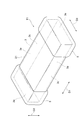
- FIG. 1 is a perspective view showing an NTC thermistor element according to an embodiment.
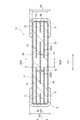
- FIG. 2 is a diagram showing a cross-sectional configuration of the NTC thermistor element according to the present embodiment.
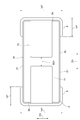
- FIG. 3 is a diagram showing a cross-sectional configuration of the NTC thermistor element according to the present embodiment.
- FIG. 4 is a diagram showing a cross-sectional configuration of the NTC thermistor element according to the present embodiment.
- FIG. 5 is a diagram showing an internal electrode.
- FIG. 6 is a diagram showing an internal electrode and a dummy electrode.
- FIG. 7 is a diagram showing the relationship between the specific resistance ( ⁇ ) of the thermistor element and the zero load resistivity value (R 25) at 25 ° C.
- FIG. 8 is a diagram showing a cross-sectional configuration of an NTC thermistor element according to a modified example of the present embodiment.
- FIG. 1 is a perspective view showing an NTC thermistor element according to the present embodiment.
- FIG. 3 and FIG. 4 are views showing a cross-sectional configuration of the NTC thermistor element according to the present embodiment.
- FIG. 5 is a diagram showing an internal electrode.
- FIG. 6 is a diagram showing an internal electrode and a dummy electrode.
- the NTC thermistor element T1 includes a thermistor element 3 having a rectangular parallelepiped shape and a plurality of external electrodes 5.
- the NTC thermistor element T1 includes a pair of external electrodes 5.
- the pair of external electrodes 5 are arranged on the outer surface of the thermistor body 3.
- the pair of external electrodes 5 are separated from each other.
- the rectangular parallelepiped shape includes a rectangular parallelepiped shape in which the corners and ridges are chamfered, and a rectangular parallelepiped in which the corners and ridges are rounded.
- the thermistor body 3 has a pair of main surfaces 3a facing each other, a pair of side surfaces 3c facing each other, and a pair of end faces 3e facing each other.
- the pair of main surfaces 3a, the pair of side surfaces 3c, and the pair of end surfaces 3e have a rectangular shape.
- the direction in which the pair of end faces 3e face each other is the first direction D1.
- the direction in which the pair of main surfaces 3a face each other is the second direction D2.
- the direction in which the pair of side surfaces 3c face each other is the third direction D3.
- the NTC thermistor element T1 is solder-mounted on an electronic device, for example. Electronic devices include, for example, circuit boards or electronic components.
- one main surface 3a faces the electronic device.
- One main surface 3a is arranged so as to form a mounting surface.
- One main surface 3a is a mounting surface.
- the other main surface 3a may be a mounting surface.
- the first direction D1 is a direction orthogonal to each end face 3e, and is orthogonal to the second direction D2.
- the second direction D2 is a direction orthogonal to each main surface 3a
- the third direction D3 is a direction orthogonal to each side surface 3c.
- the third direction D3 is a direction parallel to each main surface 3a and each end surface 3e, and is orthogonal to the first direction D1 and the second direction D2.
- the pair of side surfaces 3c extend in the second direction D2 so as to connect the pair of main surfaces 3a.
- the pair of side surfaces 3c also extends in the first direction D1.
- the pair of end faces 3e extend in the second direction D2 so as to connect the pair of main faces 3a.
- the pair of end faces 3e also extends in the third direction D3.
- the length of the thermistor body 3 in the first direction D1 is the length of the thermistor body 3.
- the length of the thermistor body 3 in the second direction D2 is the thickness TH of the thermistor body 3.
- the length of the thermistor body 3 in the third direction D3 is the width of the thermistor body 3.
- the length of the thermistor body 3 is less than 0.4 mm.
- the width of the thermistor body 3 is less than 0.2 mm.
- the thickness TH of the thermistor body 3 is less than 0.2 mm.
- the length of the thermistor element 3 is, for example, 0.225 mm
- the length of the NTC thermistor element T1 in the first direction D1 is, for example, 0.240 mm.
- the width of the thermistor element 3 is, for example, 0.1 mm
- the length of the NTC thermistor element T1 in the third direction D3 is, for example, 0.115 mm.
- the NTC thermistor element T1 is 0201 size in JIS notation.
- the NTC thermistor element T1 has a size of 00804 in EIA notation.
- the thickness TH of the thermistor element 3 is, for example, 0.0446 mm, and the length of the NTC thermistor element T1 in the second direction D2 is, for example, 0.0596 mm. That is, the NTC thermistor element T1 has a low profile.
- the thermistor body 3 is configured by laminating a plurality of thermistor layers in the second direction D2.
- the thermistor body 3 has a plurality of thermistor layers that are laminated. In the thermistor element 3, the stacking direction of the plurality of thermistor layers coincides with the second direction D2.
- Each thermistor layer is composed of, for example, a sintered body of a ceramic green sheet containing an NTC thermistor material that functions as an NTC thermistor.
- the NTC thermistor material is, for example, a semiconductor ceramic material.
- the NTC thermistor material contains, for example, a composite oxide having a spinel structure as a main component.
- the composite oxide has two or more elements selected from transition metal elements such as Mn, Ni, Co, and Fe.
- the NTC thermistor material may contain sub-ingredients, for example, to improve properties.
- Sub-ingredients include, for example, Cu, Al, or Zr.
- the composition and content of the main component and the sub-component are appropriately determined according to the characteristics required for the NTC thermistor element T1. In the actual thermistor body 3, each thermistor layer is integrated to the extent that the boundary between the thermistor layers cannot be visually recognized.
- the external electrodes 5 are arranged at both ends of the thermistor body 3 in the first direction D1.
- One of the external electrodes 5 is arranged at one end of the thermistor body 3.
- the other external electrode 5 is arranged at the other end of the thermistor body 3.
- Each external electrode 5 is arranged on the corresponding end face 3e side of the thermistor body 3.
- the external electrodes 5 are arranged at least on the end surface 3e and one of the main surfaces 3a.
- each external electrode 5 is arranged on a pair of main surfaces 3a, a pair of side surfaces 3c, and one end surface 3e.
- the external electrodes 5 are formed on five surfaces: a pair of main surfaces 3a, one end surface 3e, and a pair of side surfaces 3c. As shown in FIGS. 2 to 4, the external electrode 5 has a portion located on each main surface 3a, a portion located on each side surface 3c, and a portion located on the end surface 3e. And have. For example, when one external electrode 5 constitutes the first external electrode, the other external electrode 5 constitutes the second external electrode.
- the pair of external electrodes 5 face each other in the first direction D1 with the thermistor body 3 interposed therebetween.
- the pair of external electrodes 5 are separated in the first direction D1.
- the external electrode 5 has a sintered metal layer. Each portion of the external electrode 5 has a sintered metal layer.
- the sintered metal layer is formed by baking a conductive paste applied to the surface of the thermistor element 3.
- the sintered metal layer is formed by sintering a metal component (metal powder) contained in the conductive paste.
- the sintered metal layer is made of a noble metal or a noble metal alloy.
- Precious metals include, for example, Ag, Pd, Au, or Pt.
- Precious metal alloys include, for example, Ag-pd alloys.
- the sintered metal layer may be made of a base metal or a base metal alloy. Base metals include, for example, Cu or Ni.
- the conductive paste contains, for example, the above-mentioned types of metal powders, glass components, organic binders, and organic solvents.
- the external electrode 5 may have a plating layer.
- the plating layer is formed on the sintered metal layer so as to cover the sintered metal layer.
- the plating layer may have a two-layer structure.
- the first layer is, for example, a Ni plating layer, a Sn plating layer, a Cu plating layer, or an Au plating layer.
- the second layer formed on the first layer is, for example, a Sn plating layer, a Sn—Ag alloy plating layer, a Sn—Bi alloy plating layer, or a Sn—Cu alloy plating layer.
- the plating layer may have a layer structure of three or more layers.
- the length Le1 of each external electrode 5 in the first direction D1 is, for example, 50 to 90 ⁇ m.
- the length Le2 of each external electrode 5 in the second direction D2 is, for example, 50 to 140 ⁇ m.
- the length Le3 of each external electrode 5 in the third direction D3 is, for example, 110 to 140 ⁇ m.
- the length Le1 is 50 ⁇ m
- the length Le2 is 59.6 ⁇ m
- the length Le3 is 115 ⁇ m.
- the length Le1 of each external electrode 5 is the same, the length Le2 of each external electrode 5 is the same, and the length Le3 of each external electrode 5 is the same.
- the NTC thermistor element T1 includes a plurality of internal electrodes.
- the plurality of internal electrodes are arranged in the thermistor body 3.
- the plurality of internal electrodes include a plurality of internal electrodes 11, 13, 15 and a plurality of dummy electrodes 17, 19.
- the plurality of internal electrodes include two internal electrodes 11, two internal electrodes 13, one internal electrode 15, one dummy electrode 17, and one dummy electrode 19.
- the internal electrode 11 constitutes the first internal electrode
- the internal electrode 13 constitutes the second internal electrode
- the internal electrode 15 constitutes the third internal electrode.
- the dummy electrode 17 constitutes the first dummy electrode
- the dummy electrode 19 constitutes the second dummy electrode.
- the plurality of internal electrodes 11, 13, 15 and the plurality of dummy electrodes 17, 19 are made of a noble metal or a noble metal alloy, similarly to the external electrode 5.
- Precious metals include, for example, Ag, Pd, Au, or Pt.
- Precious metal alloys include, for example, Ag-pd alloys.
- the plurality of internal electrodes 11, 13, 15 and the plurality of dummy electrodes 17, 19 may be made of a base metal or a base metal alloy. Base metals include, for example, Cu or Ni.
- the internal electrodes 11, 13, 15 and the dummy electrodes 17, 19 are internal conductors arranged in the thermistor body 3.
- the internal electrodes 11, 13, 15 and the dummy electrodes 17, 19 are made of a conductive material.
- the plurality of internal electrodes 11, 13, 15 and the plurality of dummy electrodes 17, 19 are configured as a sintered body of a conductive paste containing the above-mentioned types of conductive materials.
- the internal electrode 11 has a rectangular shape when viewed from the second direction D2.
- the length of the internal electrode 11 in the first direction D1 is less than half the length of the thermistor body 3.
- the length of the internal electrode 11 in the third direction D3 is smaller than the width of the thermistor body 3.
- the term "rectangular" includes, for example, a shape in which each corner is chamfered and a shape in which each corner is rounded.
- the length of the internal electrode 11 in the first direction D1 is, for example, 90 to 110 ⁇ m.
- the length of the internal electrode 11 in the third direction D3 is, for example, 45 to 75 ⁇ m.
- the thickness of the internal electrode 11 is, for example, 0.5 to 3.0 ⁇ m. In the present embodiment, the length of the internal electrode 11 in the first direction D1 is 100 ⁇ m, the length of the internal electrode 11 in the third direction D3 is 60 ⁇ m, and the thickness of the internal electrode 11 is 2. It is 0 ⁇ m.
- the two internal electrodes 11 are arranged at different positions (layers) in the second direction D2. Each internal electrode 11 has one end exposed to one end surface 3e. The portion of one of the external electrodes 5 located on the end surface 3e covers one end of each internal electrode 11. Each internal electrode 11 is directly connected to one external electrode 5 at one end exposed to one end surface 3e. Each internal electrode 11 is electrically connected to one of the external electrodes 5.
- the internal electrode 13 has a rectangular shape when viewed from the second direction D2.
- the length of the internal electrode 13 in the first direction D1 is less than half the length of the thermistor body 3.
- the length of the internal electrode 13 in the third direction D3 is smaller than the width of the thermistor body 3.
- the length of the internal electrode 13 in the first direction D1 is, for example, 90 to 110 ⁇ m.
- the length of the internal electrode 13 in the third direction D3 is, for example, 45 to 75 ⁇ m.
- the thickness of the internal electrode 13 is, for example, 0.5 to 3.0 ⁇ m.
- the length of the internal electrode 13 in the first direction D1 is 100 ⁇ m
- the length of the internal electrode 13 in the third direction D3 is 60 ⁇ m
- the thickness of the internal electrode 13 is 2. It is 0 ⁇ m.
- the shape of the internal electrode 11 and the shape of the internal electrode 13 are equivalent. "Equivalent” herein does not necessarily mean that the values match. Even if a slight difference in a preset range, a manufacturing error, or a measurement error is included, the shapes may be the same.
- the two internal electrodes 13 are arranged at different positions (layers) in the second direction D2. Each internal electrode 13 has one end exposed to the other end surface 3e. The portion of the other external electrode 5 located on the end surface 3e covers one end of each internal electrode 13. Each internal electrode 13 is directly connected to the other external electrode 5 at one end exposed to the other end surface 3e. Each internal electrode 13 is electrically connected to the other external electrode 5.
- Each internal electrode 13 is arranged at the same position (layer) as the corresponding internal electrode 11 of the two internal electrodes 11 in the second direction D2.
- One internal electrode 11 and one internal electrode 13 are located in the same layer.
- the internal electrode 11 and the internal electrode 13 are separated from each other in the first direction D1, that is, in the direction in which the pair of external electrodes 5 face each other with the thermistor body 3 interposed therebetween.
- the shortest distance SD1 between the internal electrode 11 and the internal electrode 13 is, for example, 5 to 58 ⁇ m. In this embodiment, the shortest distance SD1 is 25 ⁇ m.
- the internal electrode 15 has a rectangular shape when viewed from the second direction D2.
- the length of the internal electrode 15 in the third direction D3 is smaller than the width of the thermistor body 3.
- the length of the internal electrode 15 in the first direction D1 is, for example, 90 to 168 ⁇ m.
- the length of the internal electrode 15 in the third direction D3 is, for example, 45 to 75 ⁇ m.
- the thickness of the internal electrode 15 is, for example, 0.5 to 3.0 ⁇ m.
- the length of the internal electrode 15 in the first direction D1 is 112 ⁇ m
- the length of the internal electrode 15 in the third direction D3 is 60 ⁇ m
- the thickness of the internal electrode 15 is 2. It is 0 ⁇ m.
- the internal electrodes 15 and the internal electrodes 11 and 13 are arranged at different positions (layers) in the second direction D2.
- the internal electrode 15 does not have an exposed end on the surface of the thermistor element 3. Therefore, the internal electrode 15 is not connected to each external electrode 5.
- the internal electrode 15 faces the internal electrodes 11 and 13 in the second direction D2.
- the internal electrodes 15 and the internal electrodes 11 and 13 are arranged in the thermistor body 3 so as to face each other with a gap in the second direction D2.
- the internal electrode 15 is located between a layer in which a set of internal electrodes 11 and 13 corresponding to each other is located and a layer in which another set of internal electrodes 11 and 13 corresponding to each other are located. Is located in.
- the layers in which the internal electrodes 15 are located are the layer in which the set of internal electrodes 11 and 13 are located and the layer in which the other set of internal electrodes 11 and 13 are located. It is located in the middle of.
- the internal electrode 15 includes a portion facing the internal electrode 11, a portion facing the internal electrode 13, and a portion not facing the internal electrodes 11 and 13. The portion that does not face the internal electrodes 11 and 13 is located between the portion that faces the internal electrode 11 and the portion that faces the internal electrode 13.
- the shortest distance SD2 between the internal electrode 11 and the internal electrode 15 is, for example, 3.0 to 31.3 ⁇ m. In the present embodiment, the shortest distance SD2 between one internal electrode 11 and the internal electrode 15 and the shortest distance SD2 between the other internal electrode 11 and the internal electrode 15 are equivalent. In this embodiment, the shortest distance SD2 is 9.2 ⁇ m.
- the shortest distance SD3 between the internal electrode 13 and the internal electrode 15 is, for example, 3.0 to 31.3 ⁇ m. In the present embodiment, the shortest distance SD3 between one internal electrode 13 and the internal electrode 15 and the shortest distance SD3 between the other internal electrode 13 and the internal electrode 15 are equivalent. In the present embodiment, the shortest distance SD3 is 9.2 ⁇ m, which is equivalent to the shortest distance SD2.
- the shortest distances SD2 and SD3 are also the minimum thickness of the thermistor layer located between the internal electrodes 15 and the internal electrodes 11 and 13. The shortest distance SD2 and SD3 are smaller than the shortest distance SD1. The shortest distances SD2 and SD3 are 1/4 or less of the thickness TH of the thermistor body 3.
- the shortest distance SD4 between the internal electrode 15 and one of the external electrodes 5 is, for example, 17.5 to 30.5 ⁇ m.
- the shortest distance SD4 is the shortest distance between the corner of the internal electrode 15 and the edge of one of the external electrodes 5.
- the shortest distance SD4 between one corner of the internal electrode 15 near one external electrode 5 and the edge of one external electrode 5 facing the one corner, and one external electrode of the internal electrode 15 The shortest distance SD4 between the other corner closer to 5 and the edge of the one external electrode 5 facing the other corner is equivalent.
- the shortest distance SD4 is 24.4 ⁇ m.
- the shortest distance SD5 between the internal electrode 15 and the other external electrode 5 is, for example, 17.5 to 30.5 ⁇ m.
- the shortest distance SD5 is the shortest distance between the corner of the internal electrode 15 and the edge of the other external electrode 5.
- the shortest distance SD5 between one corner of the internal electrode 15 near the other external electrode 5 and the edge of the other external electrode 5 facing the one corner, and the other external electrode of the internal electrode 15 The shortest distance SD5 between the other corner closer to 5 and the edge of the other external electrode 5 facing the other corner is equivalent.
- the shortest distance SD5 is 24.4 ⁇ m, which is equivalent to the shortest distance SD4.
- the shortest distances SD2 and SD3 are smaller than the shortest distances SD4 and SD5.
- the dummy electrode 17 has a rectangular shape when viewed from the second direction D2.
- the length of the dummy electrode 17 in the third direction D3 is smaller than the width of the thermistor element 3.
- the length Ld1 of the dummy electrode 17 in the first direction D1 is, for example, 10 to 65 ⁇ m.
- the length of the dummy electrode 17 in the third direction D3 is, for example, 45 to 75 ⁇ m.
- the thickness of the dummy electrode 17 is, for example, 0.5 to 3.0 ⁇ m.
- the length Ld1 of the dummy electrode 17 in the first direction D1 is 30 ⁇ m
- the length of the dummy electrode 17 in the third direction D3 is 60 ⁇ m
- the thickness of the dummy electrode 17 is 2. It is 0.0 ⁇ m.
- the length of the dummy electrode 17 in the third direction D3 is equivalent to the length of the internal electrode 15 in the third direction D3.
- the dummy electrode 17 is arranged at the same position (layer) as the internal electrode 15 in the second direction D2.
- the dummy electrode 17 and the internal electrode 15 are separated from each other in the first direction D1, that is, in the direction in which the pair of external electrodes 5 face each other with the thermistor body 3 interposed therebetween.
- the dummy electrode 17 and the internal electrode 11 are arranged in the thermistor body 3 so as to face each other with a gap in the second direction D2.
- the dummy electrode 17 is located between the layer on which one internal electrode 11 is located and the layer on which the other internal electrode 11 is located.
- the layer on which the dummy electrode 17 is located is located substantially intermediate between the layer on which one internal electrode 11 is located and the layer on which the other internal electrode 11 is located.
- the entire dummy electrode 17 overlaps with the internal electrode 11.
- the dummy electrode 17 has one end exposed to one end surface 3e.
- the portion of one of the external electrodes 5 located on the end surface 3e covers one end of the dummy electrode 17.
- the dummy electrode 17 is directly connected to the one external electrode 5 at one end exposed to one end surface 3e.
- the dummy electrode 17 is electrically connected to one of the external electrodes 5.
- the length Ld1 of the dummy electrode 17 is smaller than the length Le1 of the external electrode 5 to which the dummy electrode 17 is connected.
- the length Ld1 of the dummy electrode 17 is larger than the shortest distances SD2 and SD3.
- the dummy electrode 19 has a rectangular shape when viewed from the second direction D2.
- the length of the dummy electrode 19 in the third direction D3 is smaller than the width of the thermistor element 3.
- the length Ld2 of the dummy electrode 19 in the first direction D1 is, for example, 10 to 65 ⁇ m.
- the length of the dummy electrode 19 in the third direction D3 is, for example, 45 to 75 ⁇ m.
- the thickness of the dummy electrode 19 is, for example, 0.5 to 3.0 ⁇ m.
- the length Ld2 of the dummy electrode 19 in the first direction D1 is 30 ⁇ m
- the length of the dummy electrode 19 in the third direction D3 is 60 ⁇ m
- the thickness of the dummy electrode 19 is 2.
- the length of the dummy electrode 19 in the third direction D3 is equivalent to the length of the internal electrode 15 in the third direction D3.
- the shape of the dummy electrode 17 and the shape of the dummy electrode 19 are equivalent.
- the length Ld1 and the length Ld2 are equivalent.
- the dummy electrode 19 is arranged at the same position (layer) as the internal electrode 15 in the second direction D2.
- the dummy electrode 19 and the internal electrode 15 are separated from each other in the first direction D1, that is, in the direction in which the pair of external electrodes 5 face each other with the thermistor element body 3 interposed therebetween.
- the dummy electrode 19 and the internal electrode 13 are arranged in the thermistor body 3 so as to face each other with a gap in the second direction D2.
- the dummy electrode 19 is located between the layer on which one internal electrode 13 is located and the layer on which the other internal electrode 13 is located.
- the layer on which the dummy electrode 19 is located is located substantially intermediate between the layer on which one internal electrode 13 is located and the layer on which the other internal electrode 13 is located.
- the entire dummy electrode 19 overlaps with the internal electrode 13.
- the dummy electrode 19 has one end exposed to the other end surface 3e.
- the portion of the other external electrode 5 located on the end surface 3e covers one end of the dummy electrode 19.
- the dummy electrode 19 is directly connected to the other external electrode 5 at one end exposed to the other end surface 3e.
- the dummy electrode 19 is electrically connected to the other external electrode 5.
- the length Ld2 of the dummy electrode 19 is smaller than the length Le1 of the external electrode 5 to which the dummy electrode 19 is connected.
- the length Ld2 of the dummy electrode 19 is larger than the shortest distances SD2 and SD3.
- the NTC thermistor element T1 includes a coating layer 21 as shown in FIGS. 2 to 4.
- the coating layer 21 is formed on the surface of the thermistor element 3 (a pair of main surfaces 3a, a pair of side surfaces 3c, and a pair of end surfaces 3e).
- the coating layer 21 covers the surface of the thermistor element 3. In this embodiment, substantially the entire surface of the thermistor element 3 is covered.
- the coating layer 21 is a layer made of a glass material.
- the thickness of the coating layer 21 is, for example, 0.01 to 0.5 ⁇ m. In the present embodiment, the thickness of the coating layer 21 is 0.15 ⁇ m.
- the glass material is, for example, SiO 2- Al 2 O 3- LiO 2- based crystallized glass.
- the glass material may be amorphous glass.
- the internal electrodes 11 and 13 and the dummy electrodes 17 and 19 penetrate the coating layer 21 and are connected to the corresponding external electrodes 5.
- S included in the above relational expression indicates the area of the region where the internal electrode 11 and the internal electrode 15 overlap in the second direction D2, and the internal electrode 13 and the internal electrode 15 overlap in the second direction D2. It is the total value of the area of the area.
- “N” included in the above relational expression is the number of regions in the thermistor element 3 located between the internal electrodes 11 and 13 and the internal electrodes 15 in the second direction D2.
- “T” included in the above relational expression is the distance between the internal electrodes 11 and 13 and the internal electrode 15 in the second direction D2.
- the interval T may be the shortest distances SD2 and SD3.
- the interval T is the internal electrodes 11 and 13 in the region where the internal electrode 11 and the internal electrode 15 overlap in the second direction D2 and the region where the internal electrode 13 and the internal electrode 15 overlap in the second direction D2. It may be the average value of the distance between the and the internal electrode 15 in the second direction D2.
- “ ⁇ ” included in the above relational expression is a coefficient caused by the resistance value of a portion other than the thermistor element 3.
- the parts other than the thermistor body 3 include, for example, the internal electrodes 11, 13, 15 and the external electrodes 5.
- the total value (S) is 5220 ⁇ m 2 .
- the number (n) is 2.
- the interval (T) is 9.2 ⁇ m.
- the coefficient ( ⁇ ) is 40.54.
- the zero load resistance value (R 25 ) is approximately 100,000 ⁇ .
- the resistivity ( ⁇ ) of the thermistor element 3 is approximately 4600 ⁇ ⁇ m.
- the NTC thermistor element T1 having a size of less than 0402 reduces the variation in resistance value only when the distance between the internal electrode 11 and the internal electrode 15 and the distance between the internal electrode 13 and the internal electrode 15 satisfy the following relationships. That is, unless the distance between the internal electrode 11 and the internal electrode 15 and the distance between the internal electrode 13 and the internal electrode 15 satisfy the following relationship, the NTC thermistor element T1 having a resistance value variation of less than 0402 size is reduced. Not realized.
- Each shortest distance SD2 and SD3 is smaller than the shortest distance SD1.
- the shortest distances SD2 and SD3 are smaller than the shortest distances SD4 and SD5.
- the shortest distances SD2 and SD3 are 1/4 or less of the thickness TH of the thermistor body 3.
- the NTC thermistor element T1 is less than 0402 size.
- the NTC thermistor element T1 includes a thermistor element 3, a pair of external electrodes 5, and internal electrodes 11, 13, and 15.
- the internal electrode 11 and the internal electrode 13 are separated from each other in the first direction D1 in which the pair of external electrodes 5 face each other with the thermistor body 3 interposed therebetween.
- the internal electrode 15 faces the internal electrodes 11 and 13, and is not connected to each external electrode 5.
- the shortest distances SD2 and SD3 are smaller than the shortest distances SD1, SD4 and SD5, and are 1/4 or less of the thickness TH of the thermistor body 3. Therefore, even if the NTC thermistor element T1 is smaller than 0402 size, the NTC thermistor element T1 reduces the variation in the resistance value.
- the NTC thermistor element T1 is 0201 size.
- the volume of the thermistor element 3 contained in the NTC thermistor element having a size of 0201 is smaller than the volume of the thermistor element having an NTC thermistor element having a size of 0402 or more. Therefore, the NTC thermistor element T1 having a size of 0201 is excellent in thermal responsiveness.
- the NTC thermistor element T1 includes a coating layer 21.
- the coating layer 21 covers the surface of the thermistor element 3 and is made of a glass material.
- the structure in which the coating layer 21 made of a glass material covers the surface of the thermistor element 3 ensures the electrical insulation of the surface of the thermistor element 3.
- the dummy electrode 17 is separated from the internal electrode 15 in the first direction D1 and is connected to one of the external electrodes 5.
- the dummy electrode 19 is separated from the internal electrode 15 in the first direction D1 and is connected to the other external electrode 5. Since the NTC thermistor element T1 includes dummy electrodes 17 and 19, variations in the distance between the internal electrode 11 and the internal electrode 15 (interlayer distance) and the distance between the internal electrode 13 and the internal electrode 15 (interlayer distance) are suppressed. To do. Therefore, the NTC thermistor element T1 further reduces the variation in resistance value.
- Each length Ld1 and Ld2 is smaller than the length Le1 of each external electrode 5 and larger than each shortest distance SD2 and SD3. Therefore, the NTC thermistor element T1 further reliably reduces the variation in resistance value.
- the NTC thermistor element T1 does not have to include dummy electrodes 17 and 19.
- the NTC thermistor element T1 not provided with the dummy electrodes 17 and 19 also reduces the variation in resistance value.
- the number of the internal electrodes 11 and 13 is not limited to two.
- the number of each of the internal electrodes 11 and 13 may be one.
- the number of each of the internal electrodes 11 and 13 may be three or more. In this case, the number of internal electrodes 15 may be two or more.
- the present invention can be used for NTC thermistor elements.
- Thermistor element body 5 ... External electrode, 11, 13, 15 ... Internal electrode, 17, 19 ... Dummy electrode, 21 ... Coating layer, D1 ... First direction, D2 ... Second direction, D3 ... Third direction, T1 ... NTC thermistor element.
Landscapes
- Engineering & Computer Science (AREA)
- Microelectronics & Electronic Packaging (AREA)
- Physics & Mathematics (AREA)
- Electromagnetism (AREA)
- Thermistors And Varistors (AREA)
Abstract
L'invention concerne un élément de thermistance NTC qui est de taille inférieure à 0402. Une première électrode interne est connectée à une première électrode externe. Une deuxième électrode interne est espacée de la première électrode interne et est connectée à une deuxième électrode externe. Une troisième électrode interne est opposée à la première électrode interne et à la deuxième électrode interne, et n'est pas connectée à la première électrode externe et à la deuxième électrode externe. Une distance la plus courte entre la première électrode interne et la troisième électrode interne, et la distance la plus courte entre la deuxième électrode interne et la troisième électrode interne étant inférieure à une distance la plus courte entre la première électrode interne et la deuxième électrode interne, une distance la plus courte entre la première électrode externe et la troisième électrode interne, et une distance la plus courte entre la deuxieme électrode externe et la troisième électrode interne, et sont inférieures ou égales à 1/4 l'épaisseur d'un corps d'élément de thermistance.
Priority Applications (2)
| Application Number | Priority Date | Filing Date | Title |
|---|---|---|---|
| CN202080055931.5A CN114207746B (zh) | 2019-10-02 | 2020-09-28 | Ntc热敏电阻元件 |
| US17/635,841 US11791070B2 (en) | 2019-10-02 | 2020-09-28 | NTC thermistor element |
Applications Claiming Priority (2)
| Application Number | Priority Date | Filing Date | Title |
|---|---|---|---|
| JP2019-182346 | 2019-10-02 | ||
| JP2019182346A JP2021057556A (ja) | 2019-10-02 | 2019-10-02 | Ntcサーミスタ素子 |
Publications (1)
| Publication Number | Publication Date |
|---|---|
| WO2021065807A1 true WO2021065807A1 (fr) | 2021-04-08 |
Family
ID=75271158
Family Applications (1)
| Application Number | Title | Priority Date | Filing Date |
|---|---|---|---|
| PCT/JP2020/036658 Ceased WO2021065807A1 (fr) | 2019-10-02 | 2020-09-28 | Élément de thermistance ntc |
Country Status (4)
| Country | Link |
|---|---|
| US (1) | US11791070B2 (fr) |
| JP (1) | JP2021057556A (fr) |
| CN (1) | CN114207746B (fr) |
| WO (1) | WO2021065807A1 (fr) |
Families Citing this family (2)
| Publication number | Priority date | Publication date | Assignee | Title |
|---|---|---|---|---|
| JP7707090B2 (ja) * | 2022-01-20 | 2025-07-14 | Tdk株式会社 | Ntcサーミスタ素子 |
| CN115331903A (zh) * | 2022-07-28 | 2022-11-11 | 北京擎越微电子技术有限公司 | 一种改性热敏电阻 |
Citations (5)
| Publication number | Priority date | Publication date | Assignee | Title |
|---|---|---|---|---|
| JP2003124006A (ja) * | 2002-08-23 | 2003-04-25 | Mitsubishi Materials Corp | サーミスタ |
| JP2003272903A (ja) * | 2002-03-15 | 2003-09-26 | Oizumi Seisakusho:Kk | 積層型チップサーミスタと積層型チップサーミスタの抵抗値制御方法 |
| JP2011091199A (ja) * | 2009-10-22 | 2011-05-06 | Tdk Corp | 積層電子部品 |
| JP2013539605A (ja) * | 2010-09-09 | 2013-10-24 | エプコス アーゲー | 抵抗素子及びその製造方法 |
| JP2019164899A (ja) * | 2018-03-19 | 2019-09-26 | 株式会社ノリタケカンパニーリミテド | 経時粘度が安定な導電性ペースト |
Family Cites Families (9)
| Publication number | Priority date | Publication date | Assignee | Title |
|---|---|---|---|---|
| JP3440883B2 (ja) * | 1999-06-10 | 2003-08-25 | 株式会社村田製作所 | チップ型負特性サーミスタ |
| DE10159451A1 (de) * | 2001-12-04 | 2003-06-26 | Epcos Ag | Elektrisches Bauelement mit einem negativen Temperaturkoeffizienten |
| JP4419960B2 (ja) * | 2003-10-31 | 2010-02-24 | 株式会社村田製作所 | 積層型抵抗素子 |
| JP4492737B2 (ja) * | 2008-06-16 | 2010-06-30 | 株式会社村田製作所 | 電子部品 |
| KR101761936B1 (ko) * | 2012-03-13 | 2017-07-26 | 삼성전기주식회사 | 적층 세라믹 전자 부품 |
| DE102013102686B4 (de) * | 2013-03-15 | 2026-02-12 | Tdk Electronics Ag | Elektronisches Bauelement |
| JP2015133359A (ja) * | 2014-01-09 | 2015-07-23 | 株式会社村田製作所 | 負特性サーミスタおよびその製造方法 |
| JP6418246B2 (ja) * | 2014-11-07 | 2018-11-07 | 株式会社村田製作所 | サーミスタ素子 |
| TWI584309B (zh) | 2015-02-12 | 2017-05-21 | Murata Manufacturing Co | Negative characteristic thermal resistance and its manufacturing method |
-
2019
- 2019-10-02 JP JP2019182346A patent/JP2021057556A/ja active Pending
-
2020
- 2020-09-28 CN CN202080055931.5A patent/CN114207746B/zh active Active
- 2020-09-28 US US17/635,841 patent/US11791070B2/en active Active
- 2020-09-28 WO PCT/JP2020/036658 patent/WO2021065807A1/fr not_active Ceased
Patent Citations (5)
| Publication number | Priority date | Publication date | Assignee | Title |
|---|---|---|---|---|
| JP2003272903A (ja) * | 2002-03-15 | 2003-09-26 | Oizumi Seisakusho:Kk | 積層型チップサーミスタと積層型チップサーミスタの抵抗値制御方法 |
| JP2003124006A (ja) * | 2002-08-23 | 2003-04-25 | Mitsubishi Materials Corp | サーミスタ |
| JP2011091199A (ja) * | 2009-10-22 | 2011-05-06 | Tdk Corp | 積層電子部品 |
| JP2013539605A (ja) * | 2010-09-09 | 2013-10-24 | エプコス アーゲー | 抵抗素子及びその製造方法 |
| JP2019164899A (ja) * | 2018-03-19 | 2019-09-26 | 株式会社ノリタケカンパニーリミテド | 経時粘度が安定な導電性ペースト |
Also Published As
| Publication number | Publication date |
|---|---|
| US11791070B2 (en) | 2023-10-17 |
| US20220301748A1 (en) | 2022-09-22 |
| CN114207746A (zh) | 2022-03-18 |
| JP2021057556A (ja) | 2021-04-08 |
| CN114207746B (zh) | 2024-01-16 |
Similar Documents
| Publication | Publication Date | Title |
|---|---|---|
| US10964479B2 (en) | Electronic component | |
| JP5930045B2 (ja) | セラミック電子部品 | |
| US11152154B2 (en) | Electronic component | |
| KR101471829B1 (ko) | 칩 서미스터 및 그 제조 방법 | |
| JP2019067793A (ja) | 電子部品 | |
| US9984822B2 (en) | Electronic component | |
| US11335505B2 (en) | Electronic component | |
| JP2014103327A (ja) | 積層コンデンサ | |
| JP7765255B2 (ja) | 電子部品 | |
| WO2021065807A1 (fr) | Élément de thermistance ntc | |
| KR20200001885A (ko) | 복합 전자 부품 | |
| JP5437248B2 (ja) | 電気的多層構成要素 | |
| JP2016076582A (ja) | セラミック電子部品 | |
| TWI837232B (zh) | 積層陶瓷電子零件及電路基板 | |
| JP2018041904A (ja) | 電子部品装置 | |
| JP7434863B2 (ja) | Ntcサーミスタ素子 | |
| JP2024108612A (ja) | Ntcサーミスタ素子及び電子部品装置 | |
| JP7342802B2 (ja) | 半導体セラミック電子部品の実装構造 | |
| CN121709424A (zh) | 电子部件 | |
| JP2026000558A (ja) | 積層セラミックコンデンサ | |
| JP2006186039A (ja) | 積層型バリスタ | |
| JP2024089346A (ja) | 電子部品 | |
| CN115579200A (zh) | 多层式压敏电阻及其制作方法 | |
| JP2010124010A (ja) | 貫通コンデンサ | |
| JP2001237107A (ja) | 積層型チップサーミスタ |
Legal Events
| Date | Code | Title | Description |
|---|---|---|---|
| 121 | Ep: the epo has been informed by wipo that ep was designated in this application |
Ref document number: 20871333 Country of ref document: EP Kind code of ref document: A1 |
|
| NENP | Non-entry into the national phase |
Ref country code: DE |
|
| 122 | Ep: pct application non-entry in european phase |
Ref document number: 20871333 Country of ref document: EP Kind code of ref document: A1 |