WO2021084591A1 - Endoscope - Google Patents
Endoscope Download PDFInfo
- Publication number
- WO2021084591A1 WO2021084591A1 PCT/JP2019/042226 JP2019042226W WO2021084591A1 WO 2021084591 A1 WO2021084591 A1 WO 2021084591A1 JP 2019042226 W JP2019042226 W JP 2019042226W WO 2021084591 A1 WO2021084591 A1 WO 2021084591A1
- Authority
- WO
- WIPO (PCT)
- Prior art keywords
- temperature
- tip
- elastic member
- curved portion
- melting point
- Prior art date
- Legal status (The legal status is an assumption and is not a legal conclusion. Google has not performed a legal analysis and makes no representation as to the accuracy of the status listed.)
- Ceased
Links
Images
Classifications
-
- A—HUMAN NECESSITIES
- A61—MEDICAL OR VETERINARY SCIENCE; HYGIENE
- A61B—DIAGNOSIS; SURGERY; IDENTIFICATION
- A61B1/00—Instruments for performing medical examinations of the interior of cavities or tubes of the body by visual or photographical inspection, e.g. endoscopes; Illuminating arrangements therefor
- A61B1/00064—Constructional details of the endoscope body
- A61B1/0011—Manufacturing of endoscope parts
-
- A—HUMAN NECESSITIES
- A61—MEDICAL OR VETERINARY SCIENCE; HYGIENE
- A61B—DIAGNOSIS; SURGERY; IDENTIFICATION
- A61B1/00—Instruments for performing medical examinations of the interior of cavities or tubes of the body by visual or photographical inspection, e.g. endoscopes; Illuminating arrangements therefor
- A61B1/005—Flexible endoscopes
Definitions
- the present invention relates to an endoscope having a curved portion covered with an elastic member.
- an endoscope used for medical treatment or the like has a configuration in which the insertion portion is covered with a tubular member in order to keep the insertion portion watertight.
- the outer skin is formed by forming a hard portion provided at the tip of the insertion portion with a thermoplastic resin and fusing the outer skin made of a thermoplastic resin to the hard portion. Discloses a technique for covering the insertion portion.
- a technique of forming a curved portion with resin is known.
- the technique disclosed in Japanese Patent Application Laid-Open No. 2007-159845 is applied to an endoscope having a curved portion formed of a resin, the exodermis is fused to the curved portion, and the curved portion is deformed. It will be hindered.
- the present invention solves the above-mentioned problems, and an object of the present invention is to provide an endoscope that does not interfere with the operation of the curved portion and can be manufactured at low cost.
- the endoscope according to one aspect of the present invention is composed of an insertion portion having a fusion surface formed of a resin material having a melting point of a first temperature and a resin material having a melting point of a second temperature higher than the first temperature. It is formed and interposed at a predetermined position of the insertion portion, and is formed in a tubular shape with a curved portion that can be curved in a predetermined direction and a resin material different from the fusion surface, and the end portion is fused to the fusion surface. Includes elastic members and.
- FIG. 1 shows the schematic structure of the endoscope of the 1st Embodiment. It is a partial cross-sectional view of the insertion part of the 1st Embodiment. It is a partial cross-sectional view of the insertion part of the 2nd Embodiment. It is a partial cross-sectional view of the insertion part of the 3rd Embodiment.
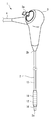
- FIG. 1 is a diagram schematically showing the configuration of the endoscope 1 of the present embodiment.
- the endoscope 1 has an elongated insertion portion 2 inserted into a subject, an operation portion 3 connected to a base end 2b of the insertion portion 2, and a connection cable 4 extending from the operation portion 3. And, including.
- the subject into which the insertion portion 2 is inserted may be a living thing such as a human being, or a non-living body such as a machine or a building.
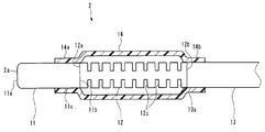
- the insertion portion 2 is configured such that the tip component portion 11, the curved portion 12, and the flexible tube 13 are connected in this order from the tip 2a to the base end 2b. Further, the curved portion 12 is covered with a tubular elastic member 14.
- FIG. 2 is a partial cross-sectional view of the elastic member 14 cut by a plane including the central axis of the insertion portion 2 in order to make it easier to see the tip component portion 11, the curved portion 12, and the flexible tube 13.
- the left-right direction is the longitudinal direction of the insertion portion 2 facing the drawing.
- the left side in FIG. 2 is the tip 2a side of the insertion portion 2
- the right side in FIG. 2 is the base end 2b side of the insertion portion 2.
- the image pickup apparatus includes an image sensor (imager), an objective lens, and the like. Further, the tip component 11 is provided with an illumination window (not shown) that emits illumination light that illuminates the subject of the image pickup apparatus.
- the connection cable 4 includes a connector that is connected to a processor that is an external device.
- the endoscope 1 has a form of a so-called videoscope, and an image captured by an imaging device is displayed on an image display device connected to a processor.
- the light source of the illumination light may be arranged in the tip component 11 or may be arranged in the processor. Since the image pickup apparatus and the illumination window arranged in the tip component 11 have known configurations, detailed description thereof will be omitted.
- the tip component 11 is a columnar member extending along the longitudinal direction of the insertion portion 2. A space for holding the above-mentioned imaging device, an illumination window, and the like is formed in the tip component 11. That is, the tip component 11 is a frame-shaped member that holds a built-in object such as an image pickup device and an illumination window at a predetermined position in the vicinity of the tip 2a of the insertion portion 2.
- the internal components may include pipelines and electronic components.
- the tip component 11 may be composed of a single member, or may be composed of a combination of a plurality of members.
- the tip component 11 includes a fusion surface 11c formed of a first material which is a thermoplastic resin on at least a part of the outer peripheral surface.
- the fusion surface 11c has at least a predetermined width in the longitudinal direction of the insertion portion 2 on the outer peripheral surface of the tip component 11, and is arranged over the entire circumferential direction.
- the melting point of the first material is the first temperature T1.
- the tip component 11 is a single member formed of a first material which is a resin.
- the tip component 11 is a resin molded product using the first material. Therefore, in the present embodiment, the entire outer peripheral surface of the tip component 11 is the fusion surface 11c.
- the first material is a so-called engineering plastic, but the type thereof is not particularly limited as long as it satisfies the condition of the relationship with the physical properties of the materials constituting the curved portion 12 and the elastic member 14 described later.
- the first material is polycarbonate (PC).
- the melting point, the first temperature T1 is approximately 160 ° C.
- the first material is styrene butane acrylonitrile copolymer (ABS), polymethylmethacrylate (PMMA), polyoxymethylene (POM), polypropylene (PP), polyamide (PA), high-density polyethylene (HDPE), or the like. There may be.
- the curved portion 12 is curved in a predetermined direction according to the movement of the operating lever 30 provided on the operating portion 3.
- the operation lever 30 is a member operated by the user of the endoscope 1.
- the curved portion 12 is connected to the tips of a plurality of wires (not shown) inserted into the insertion portion 2.
- the base ends of the plurality of wires are connected to a wire traction mechanism arranged in the operation unit 3.
- the wire traction mechanism changes the individual traction amounts of the plurality of wires according to the movement of the operating lever 30.
- the bending direction and angle of the curved portion 12 change according to a change in the traction amount of the plurality of wires. Since the configuration of the curved portion 12 whose bending direction and angle change according to the change in the traction amount of the plurality of wires is known, detailed description thereof will be omitted.
- the curved portion 12 is a columnar member that has flexibility and extends along the longitudinal direction of the insertion portion 2.
- the curved portion 12 is formed of a second material which is a thermoplastic resin.
- the second temperature T2 which is the melting point of the second material, is higher than the first temperature T1 which is the melting point of the first material.
- the type of the second material is so-called engineering plastic, but the type is not particularly limited.
- the difference between the second temperature T2, which is the melting point of the second material, and the first temperature, which is the melting point of the first material, is preferably 30 ° C. or higher.
- the second material is nylon 66.
- the second temperature T2 is approximately 280 ° C.
- the tip 12a of the curved portion 12 is connected to the base end portion 11b of the tip component 11.
- a space is formed in the curved portion 12 through which a plurality of wires, an electric cable connected to an image pickup device, and the like are inserted along the longitudinal direction.
- a plurality of slits 12c are formed on the outer peripheral surface of the curved portion 12 with the direction orthogonal to the longitudinal direction as the depth direction.
- the slit 12c is for reducing the bending rigidity of the curved portion 12 in a predetermined direction.
- the flexible tube 13 is a tubular member that has flexibility and extends along the longitudinal direction of the insertion portion 2.
- the tip portion 13a of the flexible tube 13 is connected to the base end 12b of the curved portion 12. That is, in the present embodiment, the curved portion 12 is interposed at a predetermined position between the tip component portion 11 of the insertion portion 2 and the flexible tube 13.
- the base end portion of the flexible pipe 13 is connected to the operating portion 3.
- a plurality of wires, an electric cable connected to an image pickup device, and the like are inserted in the flexible tube 13.
- the outer peripheral surface of the flexible tube 13 in the vicinity of the tip portion 13a is covered with a resin material.
- the elastic member 14 is a tubular member that covers the curved portion 12 and keeps the outer peripheral surface of the curved portion 12 watertight.
- the purpose of keeping the outer peripheral surface of the curved portion 12 watertight by the elastic member 14 is to prevent liquid or the like from entering the insertion portion 2 through the slit 12c.
- the elastic member 14 is formed of a third material different from the first material and the second material. That is, the tip component portion 11, the curved portion 12, and the elastic material 14 of the present embodiment are formed of different materials.
- the inner peripheral surface of the first end 14a which is one end, is fused to the fusion surface 11c of the tip component 11.
- the inner peripheral surface of the first end 14a and the fusion surface 11c are fused over the entire circumferential direction so that the liquid cannot pass through the interface.
- the third material constituting the elastic member 14 is a thermoplastic resin, and can be fused with the first material.
- the third temperature T3, which is the melting point of the third material is lower than the second temperature T2. Further, when the third temperature T3 is a value between the first temperature T1 and the second temperature T2, the third temperature T3 is a value closer to the first temperature T1 than the second temperature T2.
- the third temperature T3 is substantially the same as the first temperature T1.
- the third temperature T3 is substantially the same as the first temperature T1 means that the difference between the two is within 10 degrees.
- the type of the third material is not particularly limited as long as it has a melting point of T3 and is a material that does not allow liquids to pass through and can form a thin and flexible film.
- the third material is a polyether block amide copolymer.
- the inner peripheral surface of the second end 14b which is the other end, is fixed to the outer peripheral surface of the flexible pipe 13.
- the inner peripheral surface of the second end 14b and the flexible pipe 13 are joined over the entire circumferential direction so that the liquid cannot pass through the interface.
- the method of fixing the inner peripheral surface of the second end 14b and the flexible pipe 13 is not particularly limited.
- the inner peripheral surface of the second end 14b and the flexible pipe 13 may be fixed by an adhesive or may be fixed by fusion.
- the inner peripheral surface of the second end 14b of the elastic member 14 is joined to the outer peripheral surface of the tip portion 13a of the flexible pipe 13 by fusion.
- the outer peripheral surface of the tip portion 13a of the flexible tube 13 is covered with a fourth material which is a thermoplastic resin.
- the fourth temperature T4 which is the melting point of the fourth material, is substantially the same as the first temperature T1.
- the first end 14a of the elastic member 14 is fused to the tip component 10 arranged on the tip side of the curved portion 21 with respect to the tip 12a. Further, the second end 14b of the elastic member 14 is fixed to the flexible pipe 13 arranged on the base end side of the bending portion 21 with respect to the base end 12b. Therefore, the outer peripheral surface of the curved portion 12 is arranged in the space inside the tubular elastic member 14 whose both ends are closed, so that the outer peripheral surface is kept watertight.
- the tip component 11 and the curved portion 12, both of which are made of resin, are connected. Therefore, in the fusion step of heating and fusing the elastic member 14 and the tip component 11 at the time of assembling the endoscope 1, the adjacent curved portion 12 is also heated.
- the elastic member 14 is fused with the curved portion 12 in addition to the tip component 11 in this fusion step, the elastic member 14 hinders the deformation of the curved portion 12.
- the first temperature T1 which is the melting point of the fusion surface 11c of the tip component 11 is lower than the second temperature T2 which is the melting point of the curved portion 12, so that the heating temperature and the heating time in the fusion step are different.
- Control of at least one of the heating temperature and the heating time in the fusion process can be easily realized by using an electronically controlled heater. Further, the work of fixing the elastic member 14 to the tip component 11 by fusion is easier in a shorter time than the work of binding and fixing the tubular covering member with a thread as in a conventional endoscope, for example. It is feasible.
- the endoscope 1 of the present embodiment described above has a configuration in which the tip component 11 and the curved portion 12 are formed of resin and the elastic member 14 is fixed to the tip component 11 by fusion, the number of parts is large. It is possible to reduce the number of assembly work man-hours. Further, in the endoscope 1 of the present embodiment, since the melting points of the tip constituent portion 11 and the elastic member 14 are set lower than the melting points of the curved portion 12, the elastic member 14 is fused to the tip constituent portion 11. In the fusion step of fixing, fusion of the elastic member 14 and the curved portion 12 can be reliably and easily prevented. Therefore, the endoscope 1 of the present embodiment does not interfere with the operation of the curved portion 12, and can be manufactured at low cost.
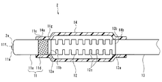
- the configuration of the tip component 11 is different from that of the first embodiment.
- the tip component 11 of the present embodiment is configured by combining a plurality of members made of different materials.
- the tip component portion 11 includes an annular portion 11d formed of the first material and a main body portion 11e formed of the fifth material.
- the main body 11e is a resin molded product using a fifth material which is a thermoplastic resin.
- the fifth temperature T5 which is the melting point of the fifth material, is higher than the first temperature T1 which is the melting point of the first material.
- the fifth temperature may be the second temperature or higher.
- the second temperature is the melting point of the second material constituting the curved portion 12, as described in the first embodiment.
- the main body portion 11e is a columnar member extending from the tip end 11a of the tip end component 11 to the base end portion 11b along the longitudinal direction of the insertion portion 2. That is, the tip 12a of the curved portion 12 is connected to the main body portion 11e. Further, a space for holding the image pickup apparatus, the illumination window, and the like is formed in the main body portion 11e.
- the main body 11e is transparent, and a part of the main body 11e is formed as an optical member 11f that constitutes at least a part of an objective lens and an illumination window of an image pickup apparatus. That is, the main body portion 11e and the optical member 11f are integrally molded.
- the types of the first material and the fifth material are not particularly limited, but in the present embodiment, as an example, the first material is styrene butagen acrylonitrile copolymer (ABS), and the fifth material is polycarbonate (PC).
- ABS styrene butagen acrylonitrile copolymer
- PC polycarbonate
- the annular portion 11d is an annular member that surrounds the entire circumferential direction on a part of the outer peripheral surface of the main body portion 11e.
- the annular portion 11d is fixed in close contact with the outer peripheral surface of the main body portion 11e.
- the annular portion 11d and the main body portion 11e are joined over the entire circumferential direction so that the liquid cannot pass through the interface.
- a mesh-like hatch is provided on the surface of the annular portion 11d for easy understanding, but this hatching does not show the cross section of the annular portion 11d.
- the method of fixing the annular portion 11d to the main body portion 11e is not particularly limited.
- the annular portion 11d and the main body portion 11e are molded and fixed by two-color molding.
- the annular portion 11d may be fixed to the main body portion 11e by adhesion or press fitting.
- the outer peripheral surface of the annular portion 11d constitutes the fusion surface 11c. That is, the inner peripheral surface of the first end 14a of the elastic member 14 is fused to the outer peripheral surface of the annular portion 11d.
- the main body portion 11e has a wall portion 11g exposed to the outside in the circumferential direction of the tip component portion 11 on the base end 11b side of the annular portion 11d.
- the outer peripheral surface of the wall portion 11g constitutes the same surface as the outer peripheral surface of the annular portion 11d. That is, the outer peripheral surface of the wall portion 11g constitutes the same surface as the fusion surface 11c.
- a part of the outer surface of the tip component 11 is composed of a fusion surface 11c formed of the first material, and the main body is another part.
- 11e is formed of a fifth material having a melting point higher than that of the first material.
- the fusion step of heating and fusing the elastic member 14 and the fusion surface 11c at the time of assembling the endoscope 1 heat is also transferred to the main body portion 11e formed of the thermoplastic resin.
- the main body 11e has a melting point higher than that of the elastic member 14 and the fusion surface 11c, it is possible to reliably prevent the main body 11e from being distorted due to heating in the fusion step.
- the occurrence of distortion in the main body 11e is prevented, for example, because it contributes to the improvement of the positioning accuracy of the image pickup apparatus.
- the prevention of distortion in the main body portion 11e means that the desired optical performance in imaging or lighting is achieved. It is more preferable because it contributes to the exertion of.
- the wall portion 11g which is the second portion having a melting point higher than that of the fusion surface 11c, is closer to the base end 11b than the fusion surface 11c which is the first portion. Is placed.
- the endoscope 1 of the present embodiment has a configuration in which the tip component 11 and the curved portion 12 are formed of resin, and the elastic member 14 is fixed to the tip component 11 by fusion, so that the number of parts is small. Moreover, the man-hours for assembling can be reduced. Further, in the endoscope 1 of the present embodiment, since the melting points of the fusion surface 11c of the tip component 11 and the elastic member 14 are set lower than the melting point of the curved portion 12, the elastic member 14 is fused. In the fusion step of fixing to the tip component 11, fusion of the elastic member 14 and the curved portion 12 can be reliably and easily prevented. Therefore, the endoscope 1 of the present embodiment does not interfere with the operation of the curved portion 12, and can be manufactured at low cost.
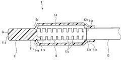
- the elastic member 14 of the present embodiment is integrally molded with the tip component 11. That is, the first end 14a of the annular elastic member 14 is integrated with the outer peripheral surface of the tip component 11.
- a fusion surface 13c is provided on the outer peripheral surface of the tip portion 13a of the flexible tube 13.
- the fused surface 13c is formed of a fourth material which is a thermoplastic resin.
- the fourth temperature T4 which is the melting point of the fourth material, is substantially the same as the first temperature T1.
- the second end 14b of the elastic member 14 is joined to the fusion surface 13c provided on the flexible pipe 13 by fusion.
- the first end 14a of the elastic member 14 is integrally molded with the tip component 10 arranged on the tip side of the curved portion 21 with respect to the tip 12a. Further, the second end 14b of the elastic member 14 is fused to the flexible pipe 13 arranged on the base end side of the bending portion 21 with respect to the base end 12b. Therefore, the outer peripheral surface of the curved portion 12 is arranged in the space inside the tubular elastic member 14 whose both ends are closed, so that the outer peripheral surface is kept watertight.
- the endoscope 1 of the present embodiment has a configuration in which the tip component 11 and the elastic member 14 are integrally molded with resin, and the end of the elastic member 14 is fixed to the flexible tube 13 by fusion.
- the number of parts can be reduced, and the number of assembly work can be reduced.
- the elastic member 14 is fused. In the fusion step of fixing to the flexible pipe 13, fusion between the elastic member 14 and the curved portion 12 can be reliably and easily prevented. Therefore, the endoscope 1 of the present embodiment does not interfere with the operation of the curved portion 12, and can be manufactured at low cost.
Landscapes
- Health & Medical Sciences (AREA)
- Life Sciences & Earth Sciences (AREA)
- Surgery (AREA)
- Engineering & Computer Science (AREA)
- Biomedical Technology (AREA)
- Heart & Thoracic Surgery (AREA)
- Pathology (AREA)
- Radiology & Medical Imaging (AREA)
- Nuclear Medicine, Radiotherapy & Molecular Imaging (AREA)
- Biophysics (AREA)
- Physics & Mathematics (AREA)
- Optics & Photonics (AREA)
- Medical Informatics (AREA)
- Molecular Biology (AREA)
- Animal Behavior & Ethology (AREA)
- General Health & Medical Sciences (AREA)
- Public Health (AREA)
- Veterinary Medicine (AREA)
- Manufacturing & Machinery (AREA)
- Endoscopes (AREA)
Abstract
L'invention concerne un endoscope comprenant : une partie d'insertion qui a une surface de fusion formée à partir d'un matériau de résine, dont le point de fusion est une première température ; une partie de courbure qui est formée à partir d'un matériau de résine, dont le point de fusion est une seconde température supérieure à la première température, qui est prise en sandwich à une position prédéterminée de la partie d'insertion, et qui est apte à se plier dans une direction prédéterminée ; et un élément élastique qui est formé dans une forme tubulaire à partir d'un matériau de résine différent de celui de la surface de fusion, et qui a une extrémité fusionnée à la surface de fusion.
Priority Applications (3)
| Application Number | Priority Date | Filing Date | Title |
|---|---|---|---|
| CN201980101529.3A CN114630612B (zh) | 2019-10-28 | 2019-10-28 | 内窥镜和内窥镜的插入部 |
| PCT/JP2019/042226 WO2021084591A1 (fr) | 2019-10-28 | 2019-10-28 | Endoscope |
| US17/726,017 US20220240752A1 (en) | 2019-10-28 | 2022-04-21 | Endoscope, insertion portion of endoscope, and method for manufacturing insertion portion |
Applications Claiming Priority (1)
| Application Number | Priority Date | Filing Date | Title |
|---|---|---|---|
| PCT/JP2019/042226 WO2021084591A1 (fr) | 2019-10-28 | 2019-10-28 | Endoscope |
Related Child Applications (1)
| Application Number | Title | Priority Date | Filing Date |
|---|---|---|---|
| US17/726,017 Continuation US20220240752A1 (en) | 2019-10-28 | 2022-04-21 | Endoscope, insertion portion of endoscope, and method for manufacturing insertion portion |
Publications (1)
| Publication Number | Publication Date |
|---|---|
| WO2021084591A1 true WO2021084591A1 (fr) | 2021-05-06 |
Family
ID=75715861
Family Applications (1)
| Application Number | Title | Priority Date | Filing Date |
|---|---|---|---|
| PCT/JP2019/042226 Ceased WO2021084591A1 (fr) | 2019-10-28 | 2019-10-28 | Endoscope |
Country Status (3)
| Country | Link |
|---|---|
| US (1) | US20220240752A1 (fr) |
| CN (1) | CN114630612B (fr) |
| WO (1) | WO2021084591A1 (fr) |
Citations (7)
| Publication number | Priority date | Publication date | Assignee | Title |
|---|---|---|---|---|
| JPH06285010A (ja) * | 1993-04-07 | 1994-10-11 | Toshiba Corp | 内視鏡装置 |
| JPH09108175A (ja) * | 1995-10-19 | 1997-04-28 | Olympus Optical Co Ltd | 内視鏡 |
| JPH09299319A (ja) * | 1996-05-15 | 1997-11-25 | Olympus Optical Co Ltd | 内視鏡 |
| JPH1094514A (ja) * | 1996-09-24 | 1998-04-14 | Olympus Optical Co Ltd | 内視鏡用湾曲管 |
| JP2007159854A (ja) * | 2005-12-14 | 2007-06-28 | Pentax Corp | 挿入部および内視鏡 |
| JP2012170628A (ja) * | 2011-02-22 | 2012-09-10 | Fujifilm Corp | 内視鏡及び内視鏡の組立方法 |
| JP2014030659A (ja) * | 2012-08-06 | 2014-02-20 | Fujifilm Corp | 内視鏡及び内視鏡装置並びに内視鏡システム |
Family Cites Families (22)
| Publication number | Priority date | Publication date | Assignee | Title |
|---|---|---|---|---|
| JPS5644701U (fr) * | 1979-09-17 | 1981-04-22 | ||
| JP2001046327A (ja) * | 1999-06-04 | 2001-02-20 | Asahi Optical Co Ltd | 内視鏡の可撓管 |
| JP2002017657A (ja) * | 2000-07-11 | 2002-01-22 | Olympus Optical Co Ltd | 内視鏡 |
| JP3854045B2 (ja) * | 2000-07-25 | 2006-12-06 | オリンパス株式会社 | 内視鏡 |
| US6991603B2 (en) * | 2002-05-17 | 2006-01-31 | Optim, Inc. | Insertion tube device |
| US7972350B2 (en) * | 2004-01-29 | 2011-07-05 | Boston Scientific Scimed, Inc. | Catheter tip |
| JP4589714B2 (ja) * | 2004-12-17 | 2010-12-01 | Hoya株式会社 | 外皮固定方法、内視鏡用可撓管および内視鏡 |
| US8206286B2 (en) * | 2005-03-25 | 2012-06-26 | Hoya Corporation | Tightening string for an endoscope, outer cover securing method, flexible tube for an endoscope, and an endoscope |
| KR101429319B1 (ko) * | 2007-02-26 | 2014-08-11 | 가부시키가이샤 마치다 세이사쿠쇼 | Mri용 연성 내시경 |
| JP2009089908A (ja) * | 2007-10-09 | 2009-04-30 | Olympus Medical Systems Corp | 内視鏡 |
| JP2009136388A (ja) * | 2007-12-04 | 2009-06-25 | Fujinon Corp | 内視鏡用可撓管の外皮熱溶着方法 |
| JP2009247498A (ja) * | 2008-04-03 | 2009-10-29 | Olympus Medical Systems Corp | 医療用挿入装置の湾曲部、並びに、その製造方法及び製造装置 |
| JP5755835B2 (ja) * | 2009-09-29 | 2015-07-29 | 富士フイルム株式会社 | 内視鏡用可撓管及びその製造方法 |
| US8747303B2 (en) * | 2009-11-02 | 2014-06-10 | Hoya Corporation | Method for affixing endoscope curved section protective sheath |
| JP2012200354A (ja) * | 2011-03-24 | 2012-10-22 | Fujifilm Corp | 内視鏡用可撓管 |
| KR20140071421A (ko) * | 2011-09-30 | 2014-06-11 | 닛뽄스틸 앤드 스미킨 메탈 프로덕츠 컴퍼니 리미티드 | 수지 구조체와 금속판을 구비한 복합 구조체 및 그 제조방법 |
| US9138566B2 (en) * | 2012-05-13 | 2015-09-22 | Bendit Technologies Ltd. | Steering tool |
| US9233225B2 (en) * | 2012-11-10 | 2016-01-12 | Curvo Medical, Inc. | Coaxial bi-directional catheter |
| CN105163644B (zh) * | 2013-06-19 | 2017-05-10 | 奥林巴斯株式会社 | 内窥镜 |
| CN105518897B (zh) * | 2013-09-03 | 2019-04-26 | 大日本印刷株式会社 | 电池用包装材料的密封层用树脂组合物 |
| JP5901859B1 (ja) * | 2014-04-15 | 2016-04-13 | オリンパス株式会社 | 内視鏡用湾曲管、内視鏡および内視鏡用湾曲管の製造方法 |
| DE102018121206A1 (de) * | 2018-08-30 | 2020-03-05 | Karl Storz Se & Co. Kg | Endoskopschaft mit einem schichtförmigen Aufbau und Verfahren zur Herstellung eines solchen |
-
2019
- 2019-10-28 WO PCT/JP2019/042226 patent/WO2021084591A1/fr not_active Ceased
- 2019-10-28 CN CN201980101529.3A patent/CN114630612B/zh active Active
-
2022
- 2022-04-21 US US17/726,017 patent/US20220240752A1/en active Pending
Patent Citations (7)
| Publication number | Priority date | Publication date | Assignee | Title |
|---|---|---|---|---|
| JPH06285010A (ja) * | 1993-04-07 | 1994-10-11 | Toshiba Corp | 内視鏡装置 |
| JPH09108175A (ja) * | 1995-10-19 | 1997-04-28 | Olympus Optical Co Ltd | 内視鏡 |
| JPH09299319A (ja) * | 1996-05-15 | 1997-11-25 | Olympus Optical Co Ltd | 内視鏡 |
| JPH1094514A (ja) * | 1996-09-24 | 1998-04-14 | Olympus Optical Co Ltd | 内視鏡用湾曲管 |
| JP2007159854A (ja) * | 2005-12-14 | 2007-06-28 | Pentax Corp | 挿入部および内視鏡 |
| JP2012170628A (ja) * | 2011-02-22 | 2012-09-10 | Fujifilm Corp | 内視鏡及び内視鏡の組立方法 |
| JP2014030659A (ja) * | 2012-08-06 | 2014-02-20 | Fujifilm Corp | 内視鏡及び内視鏡装置並びに内視鏡システム |
Also Published As
| Publication number | Publication date |
|---|---|
| US20220240752A1 (en) | 2022-08-04 |
| CN114630612A (zh) | 2022-06-14 |
| CN114630612B (zh) | 2025-11-21 |
Similar Documents
| Publication | Publication Date | Title |
|---|---|---|
| CN102123654B (zh) | 摄像装置及内窥镜 | |
| US8360965B2 (en) | Endoscopic image pickup unit | |
| EP3708061B1 (fr) | Partie de pointe pour endoscope | |
| US6409658B1 (en) | Endoscope with objective lens drive mechanism | |
| US6641530B2 (en) | Endoscope with objective lens drive mechanism | |
| JP4642936B2 (ja) | 医療用チューブ | |
| US11567288B2 (en) | Endoscope apparatus | |
| CN104334071B (zh) | 内窥镜的弯曲操作装置、具有该弯曲操作装置的内窥镜 | |
| EP3628205A1 (fr) | Procédé de fabrication d'une partie de pointe et partie de pointe pour un endoscope | |
| US20190059709A1 (en) | Insert tube and endoscope using the same | |
| EP2415387B1 (fr) | Appareil de commande d'entraînement d'objectif, appareil d'entraînement d'objectif et système d'endoscope | |
| JP6352896B2 (ja) | プローブ、および口腔内スキャナ | |
| CN103533879B (zh) | 内窥镜用摄像单元 | |
| US20180042458A1 (en) | Flexible tube, and insertion device and endoscope employing the flexible tube | |
| CN112423646A (zh) | 内窥镜的前端部 | |
| JP6054819B2 (ja) | レンズユニット、撮像装置、および移動体 | |
| JPWO2013038806A1 (ja) | 内視鏡装置 | |
| CN106999013B (zh) | 摄像单元和内窥镜 | |
| US20090105542A1 (en) | Endoscope and method of manufacturing insertion section of endoscope | |
| CN102727159A (zh) | 内窥镜 | |
| JP5133786B2 (ja) | 対物レンズユニット、内視鏡 | |
| CN114630612B (zh) | 内窥镜和内窥镜的插入部 | |
| JP7007480B2 (ja) | 内視鏡 | |
| JP3569342B2 (ja) | 内視鏡の先端部 | |
| JP6787640B2 (ja) | 挿入装置、外装部材の接続構造、内視鏡 |
Legal Events
| Date | Code | Title | Description |
|---|---|---|---|
| 121 | Ep: the epo has been informed by wipo that ep was designated in this application |
Ref document number: 19950789 Country of ref document: EP Kind code of ref document: A1 |
|
| NENP | Non-entry into the national phase |
Ref country code: DE |
|
| 122 | Ep: pct application non-entry in european phase |
Ref document number: 19950789 Country of ref document: EP Kind code of ref document: A1 |
|
| NENP | Non-entry into the national phase |
Ref country code: JP |