WO2022209968A1 - 流体回路 - Google Patents
流体回路 Download PDFInfo
- Publication number
- WO2022209968A1 WO2022209968A1 PCT/JP2022/012345 JP2022012345W WO2022209968A1 WO 2022209968 A1 WO2022209968 A1 WO 2022209968A1 JP 2022012345 W JP2022012345 W JP 2022012345W WO 2022209968 A1 WO2022209968 A1 WO 2022209968A1
- Authority
- WO
- WIPO (PCT)
- Prior art keywords
- pressure
- piston
- flow path
- chamber
- oil
- Prior art date
- Legal status (The legal status is an assumption and is not a legal conclusion. Google has not performed a legal analysis and makes no representation as to the accuracy of the status listed.)
- Ceased
Links
Images

Classifications
-
- F—MECHANICAL ENGINEERING; LIGHTING; HEATING; WEAPONS; BLASTING
- F15—FLUID-PRESSURE ACTUATORS; HYDRAULICS OR PNEUMATICS IN GENERAL
- F15B—SYSTEMS ACTING BY MEANS OF FLUIDS IN GENERAL; FLUID-PRESSURE ACTUATORS, e.g. SERVOMOTORS; DETAILS OF FLUID-PRESSURE SYSTEMS, NOT OTHERWISE PROVIDED FOR
- F15B1/00—Installations or systems with accumulators; Supply reservoir or sump assemblies
- F15B1/02—Installations or systems with accumulators
- F15B1/04—Accumulators
-
- F—MECHANICAL ENGINEERING; LIGHTING; HEATING; WEAPONS; BLASTING
- F15—FLUID-PRESSURE ACTUATORS; HYDRAULICS OR PNEUMATICS IN GENERAL
- F15B—SYSTEMS ACTING BY MEANS OF FLUIDS IN GENERAL; FLUID-PRESSURE ACTUATORS, e.g. SERVOMOTORS; DETAILS OF FLUID-PRESSURE SYSTEMS, NOT OTHERWISE PROVIDED FOR
- F15B3/00—Intensifiers or fluid-pressure converters, e.g. pressure exchangers; Conveying pressure from one fluid system to another, without contact between the fluids
-
- F—MECHANICAL ENGINEERING; LIGHTING; HEATING; WEAPONS; BLASTING
- F15—FLUID-PRESSURE ACTUATORS; HYDRAULICS OR PNEUMATICS IN GENERAL
- F15B—SYSTEMS ACTING BY MEANS OF FLUIDS IN GENERAL; FLUID-PRESSURE ACTUATORS, e.g. SERVOMOTORS; DETAILS OF FLUID-PRESSURE SYSTEMS, NOT OTHERWISE PROVIDED FOR
- F15B1/00—Installations or systems with accumulators; Supply reservoir or sump assemblies
- F15B1/02—Installations or systems with accumulators
- F15B1/024—Installations or systems with accumulators used as a supplementary power source, e.g. to store energy in idle periods to balance pump load
-
- F—MECHANICAL ENGINEERING; LIGHTING; HEATING; WEAPONS; BLASTING
- F15—FLUID-PRESSURE ACTUATORS; HYDRAULICS OR PNEUMATICS IN GENERAL
- F15B—SYSTEMS ACTING BY MEANS OF FLUIDS IN GENERAL; FLUID-PRESSURE ACTUATORS, e.g. SERVOMOTORS; DETAILS OF FLUID-PRESSURE SYSTEMS, NOT OTHERWISE PROVIDED FOR
- F15B1/00—Installations or systems with accumulators; Supply reservoir or sump assemblies
- F15B1/02—Installations or systems with accumulators
- F15B1/027—Installations or systems with accumulators having accumulator charging devices
-
- F—MECHANICAL ENGINEERING; LIGHTING; HEATING; WEAPONS; BLASTING
- F15—FLUID-PRESSURE ACTUATORS; HYDRAULICS OR PNEUMATICS IN GENERAL
- F15B—SYSTEMS ACTING BY MEANS OF FLUIDS IN GENERAL; FLUID-PRESSURE ACTUATORS, e.g. SERVOMOTORS; DETAILS OF FLUID-PRESSURE SYSTEMS, NOT OTHERWISE PROVIDED FOR
- F15B1/00—Installations or systems with accumulators; Supply reservoir or sump assemblies
- F15B1/26—Supply reservoir or sump assemblies
-
- F—MECHANICAL ENGINEERING; LIGHTING; HEATING; WEAPONS; BLASTING
- F15—FLUID-PRESSURE ACTUATORS; HYDRAULICS OR PNEUMATICS IN GENERAL
- F15B—SYSTEMS ACTING BY MEANS OF FLUIDS IN GENERAL; FLUID-PRESSURE ACTUATORS, e.g. SERVOMOTORS; DETAILS OF FLUID-PRESSURE SYSTEMS, NOT OTHERWISE PROVIDED FOR
- F15B11/00—Servomotor systems without provision for follow-up action ; Circuits therefor
- F15B11/02—Systems essentially incorporating special features for controlling the speed or the actuating force of an output member
- F15B11/028—Systems essentially incorporating special features for controlling the speed or the actuating force of an output member for controlling the actuating force
- F15B11/032—Systems essentially incorporating special features for controlling the speed or the actuating force of an output member for controlling the actuating force by means of fluid-pressure converters
-
- F—MECHANICAL ENGINEERING; LIGHTING; HEATING; WEAPONS; BLASTING
- F15—FLUID-PRESSURE ACTUATORS; HYDRAULICS OR PNEUMATICS IN GENERAL
- F15B—SYSTEMS ACTING BY MEANS OF FLUIDS IN GENERAL; FLUID-PRESSURE ACTUATORS, e.g. SERVOMOTORS; DETAILS OF FLUID-PRESSURE SYSTEMS, NOT OTHERWISE PROVIDED FOR
- F15B2211/00—Circuits for servomotor systems
- F15B2211/20—Fluid pressure source, e.g. accumulator or variable axial piston pump
- F15B2211/205—Systems with pumps
- F15B2211/2053—Type of pump
- F15B2211/20546—Type of pump variable capacity
-
- F—MECHANICAL ENGINEERING; LIGHTING; HEATING; WEAPONS; BLASTING
- F15—FLUID-PRESSURE ACTUATORS; HYDRAULICS OR PNEUMATICS IN GENERAL
- F15B—SYSTEMS ACTING BY MEANS OF FLUIDS IN GENERAL; FLUID-PRESSURE ACTUATORS, e.g. SERVOMOTORS; DETAILS OF FLUID-PRESSURE SYSTEMS, NOT OTHERWISE PROVIDED FOR
- F15B2211/00—Circuits for servomotor systems
- F15B2211/20—Fluid pressure source, e.g. accumulator or variable axial piston pump
- F15B2211/205—Systems with pumps
- F15B2211/20576—Systems with pumps with multiple pumps
-
- F—MECHANICAL ENGINEERING; LIGHTING; HEATING; WEAPONS; BLASTING
- F15—FLUID-PRESSURE ACTUATORS; HYDRAULICS OR PNEUMATICS IN GENERAL
- F15B—SYSTEMS ACTING BY MEANS OF FLUIDS IN GENERAL; FLUID-PRESSURE ACTUATORS, e.g. SERVOMOTORS; DETAILS OF FLUID-PRESSURE SYSTEMS, NOT OTHERWISE PROVIDED FOR
- F15B2211/00—Circuits for servomotor systems
- F15B2211/20—Fluid pressure source, e.g. accumulator or variable axial piston pump
- F15B2211/21—Systems with pressure sources other than pumps, e.g. with a pyrotechnical charge
- F15B2211/212—Systems with pressure sources other than pumps, e.g. with a pyrotechnical charge the pressure sources being accumulators
-
- F—MECHANICAL ENGINEERING; LIGHTING; HEATING; WEAPONS; BLASTING
- F15—FLUID-PRESSURE ACTUATORS; HYDRAULICS OR PNEUMATICS IN GENERAL
- F15B—SYSTEMS ACTING BY MEANS OF FLUIDS IN GENERAL; FLUID-PRESSURE ACTUATORS, e.g. SERVOMOTORS; DETAILS OF FLUID-PRESSURE SYSTEMS, NOT OTHERWISE PROVIDED FOR
- F15B2211/00—Circuits for servomotor systems
- F15B2211/20—Fluid pressure source, e.g. accumulator or variable axial piston pump
- F15B2211/21—Systems with pressure sources other than pumps, e.g. with a pyrotechnical charge
- F15B2211/214—Systems with pressure sources other than pumps, e.g. with a pyrotechnical charge the pressure sources being hydrotransformers
-
- F—MECHANICAL ENGINEERING; LIGHTING; HEATING; WEAPONS; BLASTING
- F15—FLUID-PRESSURE ACTUATORS; HYDRAULICS OR PNEUMATICS IN GENERAL
- F15B—SYSTEMS ACTING BY MEANS OF FLUIDS IN GENERAL; FLUID-PRESSURE ACTUATORS, e.g. SERVOMOTORS; DETAILS OF FLUID-PRESSURE SYSTEMS, NOT OTHERWISE PROVIDED FOR
- F15B2211/00—Circuits for servomotor systems
- F15B2211/60—Circuit components or control therefor
- F15B2211/625—Accumulators
-
- F—MECHANICAL ENGINEERING; LIGHTING; HEATING; WEAPONS; BLASTING
- F15—FLUID-PRESSURE ACTUATORS; HYDRAULICS OR PNEUMATICS IN GENERAL
- F15B—SYSTEMS ACTING BY MEANS OF FLUIDS IN GENERAL; FLUID-PRESSURE ACTUATORS, e.g. SERVOMOTORS; DETAILS OF FLUID-PRESSURE SYSTEMS, NOT OTHERWISE PROVIDED FOR
- F15B2211/00—Circuits for servomotor systems
- F15B2211/60—Circuit components or control therefor
- F15B2211/63—Electronic controllers
- F15B2211/6303—Electronic controllers using input signals
- F15B2211/6306—Electronic controllers using input signals representing a pressure
-
- F—MECHANICAL ENGINEERING; LIGHTING; HEATING; WEAPONS; BLASTING
- F15—FLUID-PRESSURE ACTUATORS; HYDRAULICS OR PNEUMATICS IN GENERAL
- F15B—SYSTEMS ACTING BY MEANS OF FLUIDS IN GENERAL; FLUID-PRESSURE ACTUATORS, e.g. SERVOMOTORS; DETAILS OF FLUID-PRESSURE SYSTEMS, NOT OTHERWISE PROVIDED FOR
- F15B2211/00—Circuits for servomotor systems
- F15B2211/60—Circuit components or control therefor
- F15B2211/63—Electronic controllers
- F15B2211/6303—Electronic controllers using input signals
- F15B2211/6306—Electronic controllers using input signals representing a pressure
- F15B2211/6316—Electronic controllers using input signals representing a pressure the pressure being a pilot pressure
-
- F—MECHANICAL ENGINEERING; LIGHTING; HEATING; WEAPONS; BLASTING
- F15—FLUID-PRESSURE ACTUATORS; HYDRAULICS OR PNEUMATICS IN GENERAL
- F15B—SYSTEMS ACTING BY MEANS OF FLUIDS IN GENERAL; FLUID-PRESSURE ACTUATORS, e.g. SERVOMOTORS; DETAILS OF FLUID-PRESSURE SYSTEMS, NOT OTHERWISE PROVIDED FOR
- F15B2211/00—Circuits for servomotor systems
- F15B2211/60—Circuit components or control therefor
- F15B2211/63—Electronic controllers
- F15B2211/6303—Electronic controllers using input signals
- F15B2211/6346—Electronic controllers using input signals representing a state of input means, e.g. joystick position
-
- F—MECHANICAL ENGINEERING; LIGHTING; HEATING; WEAPONS; BLASTING
- F15—FLUID-PRESSURE ACTUATORS; HYDRAULICS OR PNEUMATICS IN GENERAL
- F15B—SYSTEMS ACTING BY MEANS OF FLUIDS IN GENERAL; FLUID-PRESSURE ACTUATORS, e.g. SERVOMOTORS; DETAILS OF FLUID-PRESSURE SYSTEMS, NOT OTHERWISE PROVIDED FOR
- F15B2211/00—Circuits for servomotor systems
- F15B2211/60—Circuit components or control therefor
- F15B2211/635—Circuits providing pilot pressure to pilot pressure-controlled fluid circuit elements
- F15B2211/6355—Circuits providing pilot pressure to pilot pressure-controlled fluid circuit elements having valve means
-
- F—MECHANICAL ENGINEERING; LIGHTING; HEATING; WEAPONS; BLASTING
- F15—FLUID-PRESSURE ACTUATORS; HYDRAULICS OR PNEUMATICS IN GENERAL
- F15B—SYSTEMS ACTING BY MEANS OF FLUIDS IN GENERAL; FLUID-PRESSURE ACTUATORS, e.g. SERVOMOTORS; DETAILS OF FLUID-PRESSURE SYSTEMS, NOT OTHERWISE PROVIDED FOR
- F15B2211/00—Circuits for servomotor systems
- F15B2211/60—Circuit components or control therefor
- F15B2211/665—Methods of control using electronic components
Definitions
- the present invention relates to a fluid circuit including a pressure booster for boosting the pressure of working fluid.
- fluid circuits that drive actuators using working fluid such as hydraulic oil delivered from a fluid supply device such as a pump.
- a fluid circuit includes a pressure booster capable of delivering pressurized working fluid, and the hydraulic fluid of the pressure booster operates an actuator or accumulates pressure in an accumulator.
- the fluid circuit shown in Patent Document 1 is mainly composed of a pump, a tank, a pressure booster, and an accumulator.
- the pressure booster includes a cylinder, a piston, and biasing means.
- the cylinder has a T-shaped hollow structure when viewed from the front.
- the piston is T-shaped when viewed from the front, and is provided in the cylinder so as to be able to reciprocate in the axial direction.
- the biasing means biases the piston to one side in the axial direction.
- the space inside the cylinder is divided into a back pressure chamber and a pressure boost chamber by the piston.
- the pressure receiving area of the end face of the piston facing the back pressure chamber is larger than the pressure receiving area of the end face of the piston facing the pressure increasing chamber.
- a channel communicating with the pump and a channel communicating with the tank are connected to the back pressure chamber. By switching the switching valve, the flow path communicating with the back pressure chamber is switched.
- a channel communicating with the tank side and a channel communicating with the accumulator side are connected to the pressure increasing chamber.
- the piston moves to the other side in the axial direction by sending the working fluid from the pump to the back pressure chamber while the working fluid is stored in the pressure increasing chamber.
- the pressure booster compresses the working fluid in the pressure boosting chamber and delivers the pressurized working fluid to the accumulator side.
- the pressure in the back pressure chamber gradually decreases.
- the present invention has been made with a focus on such problems, and an object of the present invention is to provide a fluid circuit capable of continuously driving an amplifying device with a simple configuration.
- the fluid circuit of the present invention includes: A fluid supply device for delivering a working fluid, a tank for storing the working fluid, a pressure increasing device for increasing the pressure of the working fluid, and an accumulator for accumulating the pressure of the working fluid increased by the pressure increasing device,
- the pressure increasing device includes a cylinder, a piston provided in the cylinder so as to be able to reciprocate in the axial direction, and biasing means for biasing the piston toward one side in the axial direction,
- the space in the cylinder is divided by the piston into a back pressure chamber that can communicate with the fluid supply device side and the tank side, and a pressure boosting chamber that can communicate with the accumulator side,
- a fluid circuit that presses the piston to the other side in the axial direction by causing the working fluid to flow into the back pressure chamber from the fluid supply device, and sends the working fluid pressure-increased in the pressure-increasing chamber to the accumulator side.
- a first switching valve that switches between a flow path that communicates the back pressure chamber and the fluid supply device side and a first flow path that communicates the back pressure chamber and the tank side according to a change in the fluid pressure to be loaded. and a second switching valve for switching the flow path for applying fluid pressure to the first switching valve when the piston reaches the starting position on one side in the axial direction or when the piston reaches the terminal position on the other side in the axial direction.
- the biasing force of the biasing means at this time is greater than the sum of the channel resistance acting on the first channel and the channel resistance acting on the second channel.
- the first switching valve and the second switching valve use the fluid pressure to determine whether the working fluid is sent from the fluid supply device into the back pressure chamber or discharged from the back pressure chamber to the tank. can be switched. That is, the fluid circuit can continuously drive the pressure booster using the fluid pressure.
- the biasing means has just enough biasing force to move the piston to the start and end positions. Therefore, the biasing means can reliably reciprocate the piston between the starting end position and the terminal end position, and can reliably switch between the first switching valve and the second switching valve.
- the piston may have the second flow path. According to this, the extension of the second flow path can be shortened. As a result, the channel resistance force acting on the second channel can be reduced, and the urging force required for the urging means can be reduced.
- a check valve having a biasing portion that biases in the closing direction may be arranged in the second flow path. Accordingly, when moving the piston from the start position to the end position, there is no fear that the working fluid in the pressure increasing chamber will flow back into the back pressure chamber. Therefore, the pressure increasing efficiency of the pressure increasing device is good.
- the area ratio between the effective cross-sectional area of the first flow path and the effective cross-sectional area of the second flow path is larger than the area ratio between the effective pressure receiving area of the back pressure chamber and the effective pressure receiving area of the pressure increasing chamber. good too. According to this, it is possible to reduce the resistance when the working fluid passes through the second flow path while stably supplying the working fluid to the back pressure chamber and the pressure increasing chamber. Thereby, the load acting on the biasing means can be reduced.
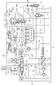
- FIG. 1 is a schematic diagram showing a fluid circuit including a pressure intensifying device of Example 1 according to the present invention
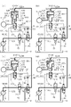
- FIG. 1 is a schematic diagram for explaining a working fluid pressure increasing cycle by a pressure increasing device of Example 1 according to the present invention
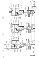
- FIG. FIG. 4 is a schematic diagram for explaining changes in the urging means and the second switching valve of the pressure booster of the first embodiment according to the present invention
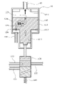
- 1 is a schematic diagram showing an enlarged main part of a pressure intensifying device according to a first embodiment of the present invention
- FIG. FIG. 5 is a schematic diagram showing a fluid circuit including a pressure booster of Example 2 according to the present invention
- a mode for implementing a fluid circuit according to the present invention will be described below based on an embodiment.
- FIG. 1 A fluid circuit according to Embodiment 1 will be described with reference to FIGS. 1 to 4.
- FIG. 1 A fluid circuit according to Embodiment 1 will be described with reference to FIGS. 1 to 4.
- the fluid circuit is applicable to hydraulic systems such as actuators, brakes, steering, transmissions, etc. in passenger cars and work vehicles such as trucks, hydraulic excavators, forklifts, cranes, and garbage trucks. be.
- the hydraulic circuit shown in FIG. 1 is an example of the fluid circuit of the present invention, and is not limited to the configuration of FIG.
- the fluid circuit of this embodiment is generally configured to move the workpiece W by operating the cylinder 5 as an actuator using hydraulic pressure.
- the fluid circuit includes a main circuit hydraulic pump 2, a switching valve 3, a hydraulic remote control valve 4, a cylinder 5, a pilot circuit hydraulic pump 6 as a fluid supply device, an electromagnetic switching valve 7, and a first switching valve. 8, an adjustable slow return valve 9, a pressure booster 10, accumulators 11 and 12, electromagnetic proportional switching valves 13 and 14, a controller C, and each oil passage.
- the hydraulic pump 2 (hereinafter sometimes simply referred to as the hydraulic pump 2) will be described.
- the hydraulic pump 2 and the pilot circuit hydraulic pump 6 are connected to a drive mechanism 1 such as a vehicle engine.
- the hydraulic pump 2 and the pilot circuit hydraulic pump 6 that are driven by the power from the drive mechanism 1 send pressure oil to the oil passages 20 and 60 .
- the pressurized oil sent from the hydraulic pump 2 flows into the switching valve 3 through the oil passage 21 branched from the oil passage 20 .
- the switching valve 3 is a 6-port, 3-position open center type switching valve.
- the switching valve 3 connects the oil passage 21 to the tank side oil passage 30 and the tank T in its neutral position. Therefore, the entire amount of pressure oil delivered from the hydraulic pump 2 is discharged to the tank T. As shown in FIG.
- the switching valve 3 connects the oil passage 22 to the head-side oil passage 50 (hereinafter simply referred to as the head-side oil passage 50) in the cylinder 5 at the extended position 3E.
- the switching valve 3 connects the rod-side oil passage 51 (hereinafter simply referred to as the rod-side oil passage 51) in the cylinder 5 to the tank-side oil passage 31 and the tank T.
- the oil passage 22 is branch-connected to the oil passage 20 and has a check valve.
- the switching valve 3 connects the oil passage 22 to the rod-side oil passage 51 at the retracted position 3S. At the same time, the switching valve 3 connects the head-side oil passage 50 to the tank-side oil passage 31 and the tank T.
- pressure oil delivered from the pilot circuit hydraulic pump 6 is supplied to the hydraulic remote control valve 4 through the oil passage 60 .
- the pressure oil supplied to the hydraulic remote control valve 4 is not limited to the pressure oil sent from the pilot hydraulic pump, and may be the working fluid sent from the hydraulic pump 2 and the cylinder 5, and may be changed as appropriate. good too.
- the hydraulic remote control valve 4 is a variable pressure reducing valve.
- the hydraulic remote control valve 4 reduces pressure oil at the primary pilot pressure to a secondary pilot pressure corresponding to the amount of operation of the operating lever 4-1.
- the pressurized oil of the pilot primary pressure referred to here is the pressurized oil delivered from the pilot circuit hydraulic pump 6 .
- the pressure oil of the pilot secondary pressure passes through the pilot signal oil passages 40, 41 and acts on the signal ports 3-1, 3-2 of the switching valve 3.
- the operation of the cylinder 5 according to the operation of the hydraulic remote control valve 4 will be explained.
- the switching valve 3 is switched to the extension position 3E.
- the pressure oil delivered from the hydraulic pump 2 flows into the head chamber 5-1 of the cylinder 5 through the head-side oil passage 50 connected to the oil passages 20 and 22.
- the pressure oil flowing out from the rod chamber 5-2 is discharged to the tank T through the tank side oil passage 31 connected to the rod side oil passage 51.
- the electric signal from the pressure sensor 42 installed on the pilot signal oil passage 40 is input to the controller C.
- the switching valve 3 is switched to the contraction position 3S. Hydraulic oil delivered from the hydraulic pump 2 flows into the rod chamber 5-2 of the cylinder 5 through the rod-side oil passage 51 connected to the oil passages 20 and 22. As shown in FIG. At the same time, the pressure oil flowing out of the head chamber 5-1 is discharged to the tank T through the tank-side oil passage 31 connected to the head-side oil passage 50. At this time, the electric signal output from the pressure sensor 43 installed on the pilot signal oil passage 41 is input to the controller C.
- a relief oil passage 23 having a relief valve is branched and connected to the oil passage 20 .
- the relief valve is opened.
- the pressure oil is discharged from the relief oil passage 23 to the tank T.
- the oil passage 60, the hydraulic remote control valve 4, the pilot signal oil passages 40 and 41, and the relief oil passage 62 are included in the configuration of the pilot circuit.
- An oil passage 61 branched from the oil passage 60 is provided with an electromagnetic switching valve 7 .
- the electromagnetic switching valve 7 blocks the oil passages 61 and 70 .
- the electromagnetic switching valve 7 connects the oil passage 70 to the oil passage 71 connected to the tank T.
- the electrical signal output from the controller C by turning the switch 15 to the ON state is input to the electromagnetic switching valve 7 through the electrical signal line 72 .
- the electromagnetic switching valve 7 connects the oil passages 61 and 70 .
- the electromagnetic switching valve 7 blocks the oil passages 70 and 71 (see FIG. 2).
- a first switching valve 8 is provided in the oil passage 70 .
- the first switching valve 8 is a switching valve that switches the oil passage to be connected according to the pressure acting on the port 8-1.
- the first switching valve 8 connects the oil passages 70 and 80 when the pressure acting on the port 8-1 is less than the predetermined value.
- the first switching valve 8 blocks the oil passages 80 and 81 .
- the oil passage 81 is connected to the tank T.
- the first switching valve 8 shuts off the oil passage 70 and the oil passage 80. At the same time, the first switching valve 8 connects the oil passages 80 and 81 (see FIGS. 2(c) and 2(d)).
- a pressure booster 10 is connected to the oil passage 80 .
- the pressure increasing device 10 further increases the pressure of the pressurized oil delivered from the pilot circuit hydraulic pump 6 and delivers it to an oil passage 100 having a check valve.
- the configuration of the pressure booster 10 will be described later.
- Oil passages 101 and 102 are branched and connected to the oil passage 100 .
- the oil passage 101 has two check valves.
- the oil passage 102 has two check valves separate from the oil passage 101 .
- An accumulator 11 and a pressure sensor 103 are connected between the two check valves in the oil passage 101 .
- a pressure sensor 103 detects the pressure of the accumulator 11 .
- An electromagnetic proportional switching valve 13 is connected downstream of the two check valves in the oil passage 101 .
- An accumulator 12 and a pressure sensor 104 are connected between the two check valves in the oil passage 102 .
- a pressure sensor 104 senses the pressure in the accumulator 12 .
- An electromagnetic proportional switching valve 14 is connected downstream of the two check valves in the oil passage 102 .
- the electromagnetic proportional switching valves 13 and 14 are of the normally closed type, and are connected to the controller C via electric signal lines.
- the controller C controls the electromagnetic proportional switching valves 13 and 14 to be closed or open based on the electrical signals input from the pressure sensors 42, 43, 103 and 104.
- the electromagnetic proportional switching valve 13 will be described below as an example.
- the electromagnetic proportional switching valve 13 When the pressure in the accumulator 11 drops, the electromagnetic proportional switching valve 13 is closed by receiving an electric signal from the controller C. As a result, the accumulator 11 can accumulate the pressurized oil delivered from the pressure increasing device 10 in an increased pressure state.
- the electromagnetic proportional switching valve 13 receives an electric signal from the controller C when the pressure in the accumulator 11 increases. Electromagnetic proportional switching valve 13 connects oil passages 101 and 105 at an opening degree corresponding to the input signal. As a result, the accumulated pressure oil delivered from the accumulator 11 is regenerated to the head chamber 5-1 of the cylinder 5 through the oil passage 107 having the check valve and the head-side oil passage 50.
- FIG. 1 illustrates the electromagnetic proportional switching valve 13
- the fluid circuit accumulates pressure in one of the accumulators 11 and 12 .
- the fluid circuit can cause the main circuit to regenerate the pressurized oil in an increased pressure state accumulated in the other fluid circuit.
- a relief oil passage 108 having a relief valve is branched from the oil passage 100 .
- Surplus oil is discharged to tank T through relief oil passage 108 .
- the pressure booster 10 will be explained.
- the spring 140 side of the pressure increasing device 10 will be described as the other axial side (that is, the lower side in the drawing), and the opposite side will be described as the one axial side (that is, the upper side in the drawing).
- the pressure booster 10 is mainly composed of a case 110 as a cylinder, a piston 120, a second switching valve 130, and a spring 140 as biasing means.
- Piston 120 is provided axially movably within case 110 .
- a spring 140 biases the piston 120 in one axial direction.
- the second switching valve 130 is enlarged to show the switching of the oil passages. 3 and 4 are diagrammatically illustrated based on the symbols used in FIGS. 1 and 2.
- the case 110 is formed in a substantially T-shaped stepped cylindrical shape when viewed from the front, and has a large-diameter cylindrical portion 111 and a small-diameter cylindrical portion 112 .
- An oil passage 80 is connected to the upper portion of the large-diameter cylindrical portion 111 .
- An oil passage 100 is connected to the lower end portion of the large-diameter cylindrical portion 111 on the outer diameter side of the small-diameter cylindrical portion 112 .
- An oil passage 113 connected to the tank T is connected to the peripheral wall of the small-diameter cylindrical portion 112 .
- the piston 120 is formed in a T-shaped stepped columnar shape when viewed from the front, and has a large diameter portion 121 and a small diameter portion 122 .
- the large-diameter portion 121 is formed such that its outer peripheral surface can slide along the inner peripheral surface of the large-diameter cylindrical portion 111 of the case 110 .
- the small-diameter portion 122 is formed such that its outer peripheral surface can slide along the inner peripheral surface of the small-diameter cylindrical portion 112 of the case 110 .
- a back pressure chamber side second oil passage 123 , a check valve 124 , and a pressure increasing chamber side second oil passage 125 are formed in the large diameter portion 121 .
- the back-pressure-chamber-side second oil passage 123 communicates with the back-pressure chamber 10-1, extends axially downward, and extends substantially orthogonally in the outer diameter direction.
- the check valve 124 is disposed between the back pressure chamber side second oil passage 123 and the pressure increasing chamber side second oil passage 125 .
- the pressure-increasing chamber-side second oil passage 125 extends radially outward from the check valve 124, extends axially downward, and communicates with the pressure-increasing chamber 10-2.
- the case 110 has a large-diameter cylindrical portion 111 with a space defined by the large-diameter portion 121 of the piston 120 into a back pressure chamber 10-1 and a pressure-increasing chamber 10-2.
- An oil passage 80 communicates with the back pressure chamber 10-1.
- An oil passage 100 communicates with the pressure increasing chamber 10-2.
- a spacer that restricts the movement of the piston 120 is fixedly arranged at the upper end in the axial direction inside the back pressure chamber 10-1.
- the case 110 when the piston 120 is housed, the case 110 has a drain chamber 10-3 defined by the small-diameter cylindrical portion 112 of the case 110 and the small-diameter portion 122 of the piston 120. As shown in FIG. An oil passage 113 communicates with the drain chamber 10-3.
- the piston 120 is configured to be able to reciprocate between a start position and an end position.
- the start position is a position where the upper end of the large-diameter portion 121 abuts on the spacer in the back pressure chamber 10-1 on the upper side in the axial direction and movement in the same direction is restricted.
- the end position is a position where the lower end of the large-diameter portion 121 abuts against the lower surface inside the pressure-increasing chamber 10-2 on the lower side in the axial direction, and movement in the same direction is restricted.
- a rod of the second switching valve 130 penetrates the bottom of the small-diameter cylindrical portion 112 of the case 110 .
- a force applied to the second switching valve 130 from pressure on the upper end surface 121 a of the large diameter portion 121 of the piston 120 acts on the second switching valve 130 .
- the biasing force of the spring 140 acts on the second switching valve 130 .
- the rod of the second switching valve 130 is kept in a state in which its upper end surface is in contact with the lower end surface of the small diameter portion 122 of the piston 120 .
- the upper end surface 121a is the rear surface of the large diameter portion 121 in this embodiment.
- the second switching valve 130 opens the drain oil passage 131 and the pilot oil passage 132. Connecting. At the same time, the second switching valve 130 blocks the pilot oil passages 132 and 133 .
- the drain oil passage 131 is connected to the tank T. Pilot oil passage 132 is connected to port 8 - 1 of first switching valve 8 .
- the pilot oil passage 133 is branched and connected to the oil passage 70 .
- the second switching valve 130 connects the pilot oil passages 132 and 133 when the piston 120 has reached the end position, that is, when movement in the same direction is restricted on the lower side in the axial direction. At the same time, the second switching valve 130 blocks the drain oil passage 131 and the pilot oil passage 132 (see FIGS. 2(b) and 2(c)).
- the spring 140 is a spring member made of an elastic material having a constant spring constant k that can expand and contract in the axial direction, and is formed to have a natural length L0 (see FIG. 3A).
- the spring 140 is fixedly installed at its proximal end (lower end in the drawing).
- a free end portion (upper end portion in the figure) of the spring 140 always contacts the lower end surface of the second switching valve 130 in a compressed state.
- the spring 140 always urges the piston 120 upward in the axial direction via the second switching valve 130 by the urging forces F S1 , F SX and F S2 generated according to the compressed positions.
- an adjustable slow return valve 9 is composed of a variable throttle portion 90, a pilot oil passage 91, and a check valve 92.
- the pilot oil passage 91 is connected to the pilot oil passage 132 across the variable throttle portion 90 .
- the check valve 92 is provided in the middle of the pilot oil passage 91 .
- FIG. 1 the pressure increasing cycle by the pressure increasing device 10 will be explained using FIGS. 1 to 4.
- FIG. 1 the pressure increasing cycle by the pressure increasing device 10 will be explained using FIGS. 1 to 4.
- the switch 15 is in the OFF state, and the electromagnetic switching valve 7 blocks the oil passages 61,70.
- the piston 120 Before the pressure increase starts, the piston 120 is located at the starting end position on the upper side in the axial direction inside the case 110 . As described above, the position where the piston 120 reaches before the pressure increase by the pressure increasing device 10 is started and the upward movement in the axial direction is restricted is the start position of the piston 120 . In the following description, it is simply referred to as the start position.
- the spring 140 has a length L1 (see FIG. 3(b)) slightly compressed from the natural length L0 (see FIG. 3(a)) (L0>L1).
- the spring 140 has a maximum compressed length L2 (see FIG. 3(d)) (L1>L2). Needless to say, the spring 140 in this state is within the elastic deformation range.
- the biasing force F S1 of the spring 140 maintains the piston 120 at the starting position.
- the second switching valve 130 connects the oil passages 131 and 132 after the piston 120 reaches the starting position.
- substantially the same pressure as the oil in the tank T is acting on the port 8-1 of the first switching valve 8.
- the first switching valve 8 connects the oil passages 70,80.
- the switch 15 When starting pressure increase by the pressure increase device 10, the switch 15 is turned on. As a result, the electromagnetic switching valve 7 connects the oil passages 61 and 70, as shown in FIG. 2(a). A part of the pressurized oil delivered from the pilot circuit hydraulic pump 6 passes through the oil passages 60 and 61, the electromagnetic switching valve 7, the oil passage 70, the first switching valve 8, and the oil passage 80 to increase the pressure. It flows into the back pressure chamber 10-1 in the device 10.
- the fluid pressure PH1 of the pressure oil delivered from the pilot circuit hydraulic pump 6 is 1 MPa, as described above.
- the pressure of oil in the pressure increasing chamber 10-2 is 0.1 MPa. Therefore, there is a difference in pressure between the pressure in the back pressure chamber side second oil passage 123 communicating with the back pressure chamber 10-1 and the pressure in the pressure increasing chamber side second oil passage 125 communicating with the pressure increasing chamber 10-2. is occurring.
- the check valve 124 Due to this differential pressure, the check valve 124 is opened, and pressure oil flows from the back pressure chamber 10-1 into the pressure increasing chamber 10-2. Due to this inflow of pressurized oil and movement of the piston 120, the pressure in the pressure increasing chamber 10-2 is raised above the pressure in the back pressure chamber 10-1 in an extremely short period of time. Therefore, the check valve 124 is closed.
- the area S1 is the area of the upper end surface 121a of the large diameter portion 121 of the piston 120 .
- the area S2 is the area of the annular lower end surface 121b of the large diameter portion 121 of the piston 120 .
- Area S3 is the cross-sectional area of small diameter portion 122 in piston 120 .
- This pressing force FH1 presses the piston 120 downward in the axial direction.
- this pressing force F H1 exceeds the biasing force F S1 of the spring 140 at the starting position (F H1 >F S1 ).
- the piston 120 smoothly moves toward the terminal position on the axially downward side.
- the pressure of the oil in the drain chamber 10-3 is substantially constant regardless of the movement of the piston 120. Further, the oil in the drain chamber 10-3 repeatedly flows in and out as the piston 120 moves. Therefore, a description of the effect of the oil in the drain chamber 10-3 is omitted.
- Lx which is the length of the spring 140 while the piston 120 is moving between the start position and the end position, is a variable between the lengths L1 and L2 (L1 >Lx>L2).
- the pressing force F H1 due to the fluid pressure of the pressure oil delivered from the pilot circuit hydraulic pump 6 exceeds the biasing force F S2 (F H1 >>> F S2 ).
- the spring 140 is configured to have an urging force lower than the pressing force FH1 of the pressurized oil delivered from the pilot circuit hydraulic pump 6 when the piston 120 reaches the end position.
- the area ratio between the area S1 of the upper end surface 121a and the area S2 of the lower end surface 121b of the piston 120 is set so that the piston 120 can reach the terminal position even if the pressure in the pressure increasing chamber 10-2 is increased. , and the biasing force F S2 of the spring 140 are adjusted.
- the second switching valve 130 connects the oil passages 132, 133 after the piston 120 reaches the terminal position. As a result, pressure oil flows from the pilot circuit hydraulic pump 6 into the pilot oil passage 132 via the pilot oil passage 133 .
- an adjustable slow return valve 9 is configured in the pilot oil passage 132 .
- the pressure oil that has passed through the variable throttle portion 90 in the adjustable slow return valve 9 acts on the port 8-1.
- the variable throttle section 90 whose opening degree can be adjusted can change the time required for the pressure acting on the port 8-1 to reach or exceed a predetermined value according to its opening degree. That is, the variable throttle section 90 can adjust the time until the piston 120 starts moving from the terminal position toward the starting position.
- the first switching valve 8 connects the oil passages 80 and 81 as shown in FIG. 2(c).
- the pressure oil in the back pressure chamber 10-1 passes through the oil passage 80, the first switching valve 8 and the oil passage 81 and is discharged to the tank T. That is, the oil passages 80 and 81 constitute the first flow passage of the present invention.
- the pressure P Y in the back pressure chamber 10-1 decreases and approaches the pressure P 0 of the oil stored in the tank T (P H1 >>P Y >P 0 ).
- the piston 120 begins to move upward in the axial direction (F S2 >F HY ), as indicated by the bold white arrow in FIG.
- part of the oil in the back pressure chamber 10-1 flows out to the oil passage 80, as indicated by the thick black arrow in FIG. Note that the piston 120 may start moving upward in the axial direction when the pressure PY becomes the same pressure as P0 .
- the flow path resistance R1 acts on the oil passing through the oil path 80
- the flow path resistance R2 acts on the oil passing through the second oil paths 123 and 125 and the check valve 124.
- the flow path resistance R1 is derived from the viscosity of the oil, the coefficient of friction inside the pipes of the oil paths 80 and 81, the inner diameter, the length, and the like.
- the flow resistance force R2 is determined by the coil spring 124a (FIG. 3, (see FIG. 4)).
- the spring 140 expands and weakens the biasing force FSX . Then, when the piston 120 reaches the starting position, the biasing force F S1 of the spring 140 becomes the minimum value. However, the biasing force F S1 of the spring 140 exceeds the sum of the pressing force F H0 , the flow resistance force R1 and the flow resistance force R2 (F S1 >F H0 +R1+R2).
- the spring 140 when the piston 120 reaches the starting position, the spring 140 has an urging force that exceeds the sum of the pressure force FHO by the oil whose passage is opened, the passage resistance force R1, and the passage resistance force R2. It is configured.
- second oil passages 123 and 125 and a check valve 124 are provided inside the piston 120 . Therefore, the second oil passage and the check valve are arranged outside the case 110, that is, the second oil passage is detoured, and the back pressure chamber 10-1 and the pressure increasing chamber 10-2 are communicated (see FIG. 5). ), the extension of the second oil passages 123 and 125 can be shortened.
- the second oil passages 123 and 125 having short extensions can reduce the flow path resistance R2 acting on the oil passing through the second oil passages 123 and 125 . Therefore, the biasing force F S1 of the spring 140 can be kept small.
- the inner diameter D1 of the oil passages 80, 81 is larger than the inner diameter D2 of the second oil passages 123, 125 (D1>D2).
- the effective cross-sectional area S11 of the oil passages 80, 81 is larger than the effective cross-sectional area S12 of the second oil passages 123, 125 (S11>S12).
- the area ratio between the effective cross-sectional area S11 and the effective cross-sectional area S12 is larger than the area ratio between the area S1 of the upper end surface 121a and the area S2 of the lower end surface 121b (S11/S12>S1/S2). This enables stable supply of oil to the back pressure chamber 10-1 and the pressure increasing chamber 10-2.
- the valve body of the check valve 124 can reduce the pressure-receiving area of Furthermore, the urging force of the coil spring 124a can be reduced as the pressure receiving area is reduced. That is, the flow path resistance R2 when the oil passes through the second oil paths 123, 125 can be reduced. Thereby, the load acting on the spring 140 can be reduced.
- the back pressure chamber 10-1 and the pressure increasing chamber 10-2 are directly communicated by the second oil passages 123, 125 and the check valve 124. Therefore, the influence on the tank T side can be reduced.
- the second switching valve 130 blocks both the oil passages 131, 132 and the oil passages 132, 133 as described above. Therefore, it is prevented that the first switching valve 8 operates and the oil passage is switched unintentionally.
- the second switching valve 130 connects the oil passages 132 and 131 when the piston 120 reaches the starting position.
- the pressure oil acting on the port 8-1 passes through the pilot oil passage 91 and the check valve 92 and is discharged to the tank T.
- the first switching valve 8 opens the oil passages 70, 80 as shown in FIG. 2(a).
- the pressure oil is sent from the pilot circuit hydraulic pump 6 to the back pressure chamber 10-1 using the fluid pressure by the first switching valve 8 and the second switching valve 130. , to discharge the oil from the back pressure chamber 10-1 to the tank T, the above cycle can be repeated. That is, the pressure booster 10 can be continuously driven using the fluid pressure.
- the fluid circuit in this embodiment can continuously reciprocate the piston 120 through the cooperation of the mechanically operated first switching valve 8, second switching valve 130, and spring 140. . That is, high fluid pressure can be continuously generated without electrical control. This eliminates the need for conventional electric control and simplifies the configuration of the fluid circuit.
- the spring 140 has just enough urging force to move the piston 120 to the start and end positions. Therefore, the spring 140 can reliably reciprocate the piston 120 between the starting end position and the terminal end position, and can reliably switch the first switching valve 8 and the second switching valve 130 .
- a check valve 124 having a coil spring 124a is arranged between the second oil passages 123, 125. Therefore, when the piston 120 is moved from the start position to the end position, the pressurized oil in the pressure increasing chamber 10-2 does not flow back into the back pressure chamber 10-1, and the pressure increasing efficiency is good.
- the pressurized oil intensified by the pressure intensifying device 10 is delivered by the downward movement of the piston 120 in the axial direction and accumulated in the accumulators 11 and 12 . Therefore, the generation of pulsation due to the reciprocating motion of the piston 120 is prevented. As a result, the pressure booster 10 can deliver a substantially constant amount of pressurized oil to the accumulators 11 and 12 .
- An oil passage 107 having check valves provided between the accumulators 11 and 12 and the main circuit is connected from the check valve to the main circuit side and from the check valve to the accumulators 11 and 12 side, that is, the upstream side. can be separated. As a result, even if the main circuit side is of high pressure specification, the configuration of the accumulators 11 and 12 is set to the minimum pressure specification required for regeneration to the destination of the high fluid pressure. can be sent.
- a fluid circuit according to Embodiment 2 will be described with reference to FIG. It should be noted that descriptions of configurations that are the same as those of the first embodiment will be omitted.
- the first flow path connecting the back pressure chamber 10-1 in the pressure booster 210 and the tank T is composed of the oil passage 280 and the oil passage 81. It is
- the second flow path connecting the back pressure chamber 10-1 and the pressure increasing chamber 10-2 is formed by a part of the oil passage 280, an oil passage 82 branched from the oil passage 280, and an oil passage 84. It is configured.
- a check valve 83 is arranged between the oil passages 82 and 84 . That is, the large diameter portion 221 of the piston 220 does not include the back pressure chamber side second oil passage 123, the check valve 124, and the pressure increasing chamber side second oil passage 125 of the first embodiment.
- Example 2 Even with such a configuration, the fluid circuit of Example 2 can continuously generate high fluid pressure without electrical control.
- the second flow path is simplified. can be configured to
- the working fluid is oil, but the working fluid is not limited to this, and may be changed appropriately as long as it is a fluid.
- the fluid supply device is described as being a pilot circuit hydraulic pump, but it is not limited to this, and may be a main circuit hydraulic pump, an actuator, an accumulator, or the like, and may be changed as appropriate. may be
- the urging means is a spring.
- the urging force when the piston reaches the end position is applied to the piston by the fluid pressure of the pump.
- the biasing force when the piston reaches the start position is less than the pressing force and is greater than the sum of the flow resistance force acting on the first flow path and the flow resistance force acting on the second flow path.
- the spring urges the piston upward in the axial direction via the second switching valve. It is good also as a structure which is urged
- the urging means for the check valve provided in the second flow path is a coil spring. may be changed as appropriate.
- the configuration in which the adjustable slow return valve is provided between the first switching valve and the second switching valve has been described. may be omitted.
Landscapes
- Engineering & Computer Science (AREA)
- Physics & Mathematics (AREA)
- Fluid Mechanics (AREA)
- Mechanical Engineering (AREA)
- General Engineering & Computer Science (AREA)
- Fluid-Pressure Circuits (AREA)
Abstract
Description
作動流体を送出する流体供給装置と、作動流体を貯留するタンクと、作動流体を増圧する増圧装置と、前記増圧装置で増圧された作動流体を蓄圧するアキュムレータと、を備え、
前記増圧装置は、シリンダと、軸方向に往復動可能に前記シリンダ内に設けられたピストンと、前記ピストンを軸方向一方側に向けて付勢する付勢手段と、を具備し、
前記シリンダ内の空間は、前記ピストンにより、前記流体供給装置側及び前記タンク側に連通可能な背圧室と、前記アキュムレータ側に連通可能な増圧室とに区画されており、
前記流体供給装置から前記背圧室に作動流体を流入させることで前記ピストンを軸方向他方側に押圧し、前記増圧室にて増圧された作動流体を前記アキュムレータ側に送出する流体回路であって、
負荷される流体圧の変化に応じて、前記背圧室及び前記流体供給装置側を連通させる流路と、前記背圧室及び前記タンク側を連通させる第1流路とを切り換える第1切換弁と、前記ピストンが軸方向一方側の始端位置に到達したとき、または前記ピストンが軸方向他方側の終端位置に到達したときに前記第1切換弁に流体圧を負荷する流路を切り換える第2切換弁と、前記背圧室及び前記増圧室を連通させる第2流路と、を有し、
前記ピストンが前記終端位置に到達するときの前記付勢手段の付勢力は、前記流体供給装置による流体圧により前記ピストンに作用する押圧力よりも小さく、かつ、前記ピストンが前記始端位置に到達するときの前記付勢手段の付勢力は、前記第1流路に作用する流路抵抗力と、前記第2流路に作用する流路抵抗力との和よりも大きい。
これによれば、第1切換弁、第2切換弁により、流体圧を利用して背圧室内に流体供給装置から作動流体を送出するか、背圧室からタンクに作動流体を排出するかを切り換えることができる。すなわち、流体回路は、流体圧を利用して増圧装置を連続駆動させることができる。さらに付勢手段は、ピストンを始端位置及び終端位置に移動させるために過不足のない付勢力を有している。そのため、付勢手段は、ピストンを確実に始端位置と終端位置とに往復動させることができ、第1切換弁、第2切換弁を確実に切り替えることができる。
これによれば、第2流路の延長を短くすることができる。これにより、第2流路に作用する流路抵抗力を小さくして、付勢手段に求められる付勢力を軽減することができる。
これによれば、ピストンを始端位置から終端位置に移動させるにあたって、増圧室内の作動流体は背圧室に逆流する虞がない。そのため、増圧装置による増圧効率がよい。
これによれば、背圧室と増圧室に、安定した作動流体の送出を可能としつつ、第2流路を作動流体が通過する際の抵抗を小さくすることができる。これにより、付勢手段に作用する負荷を軽減することができる。
6 パイロット回路用油圧ポンプ(流体供給装置)
8 第1切換弁
10 増圧装置
10-1 背圧室
10-2 増圧室
11,12 アキュムレータ
80 油路(第1流路)
81 油路(第1流路)
110 ケース(シリンダ)
120 ピストン
123 背圧室側第2油路(第2流路)
124 逆止弁(第2流路の逆止弁)
124a バネ(第2流路の逆止弁の付勢部)
125 増圧室側第2油路(第2流路)
130 第2切換弁
140 スプリング(付勢手段)
210 増圧装置
82,84 油路(第2流路)
83 逆止弁(第2流路の逆止弁)
220 ピストン
280 油路(第1流路,第2流路)
T タンク
Claims (4)
- 作動流体を送出する流体供給装置と、作動流体を貯留するタンクと、作動流体を増圧する増圧装置と、前記増圧装置で増圧された作動流体を蓄圧するアキュムレータと、を備え、
前記増圧装置は、シリンダと、軸方向に往復動可能に前記シリンダ内に設けられたピストンと、前記ピストンを軸方向一方側に向けて付勢する付勢手段と、を具備し、
前記シリンダ内の空間は、前記ピストンにより、前記流体供給装置側及び前記タンク側に連通可能な背圧室と、前記アキュムレータ側に連通可能な増圧室とに区画されており、
前記流体供給装置から前記背圧室に作動流体を流入させることで前記ピストンを軸方向他方側に押圧し、前記増圧室にて増圧された作動流体を前記アキュムレータ側に送出する流体回路であって、
負荷される流体圧の変化に応じて、前記背圧室及び前記流体供給装置側を連通させる流路と、前記背圧室及び前記タンク側を連通させる第1流路とを切り換える第1切換弁と、前記ピストンが軸方向一方側の始端位置に到達したとき、または前記ピストンが軸方向他方側の終端位置に到達したときに前記第1切換弁に流体圧を負荷する流路を切り換える第2切換弁と、前記背圧室及び前記増圧室を連通させる第2流路と、を有し、
前記ピストンが前記終端位置に到達するときの前記付勢手段の付勢力は、前記流体供給装置による流体圧により前記ピストンに作用する押圧力よりも小さく、かつ、前記ピストンが前記始端位置に到達するときの前記付勢手段の付勢力は、前記第1流路に作用する流路抵抗力と、前記第2流路に作用する流路抵抗力との和よりも大きい流体回路。 - 前記ピストンは、前記第2流路を有している請求項1に記載の流体回路。
- 前記第2流路には、閉塞方向に付勢する付勢部を有する逆止弁が配置されている請求項1または2に記載の流体回路。
- 前記第1流路の有効断面積と前記第2流路の有効断面積との面積比は、前記背圧室の有効受圧面積と前記増圧室の有効受圧面積との面積比よりも大きい請求項3に記載の流体回路。
Priority Applications (4)
| Application Number | Priority Date | Filing Date | Title |
|---|---|---|---|
| CN202280023917.6A CN117098921A (zh) | 2021-03-31 | 2022-03-17 | 流体回路 |
| EP22780187.5A EP4317705A4 (en) | 2021-03-31 | 2022-03-17 | FLUID CIRCUIT |
| US18/284,249 US12292060B2 (en) | 2021-03-31 | 2022-03-17 | Fluid circuit |
| JP2023510945A JP7669475B2 (ja) | 2021-03-31 | 2022-03-17 | 流体回路 |
Applications Claiming Priority (2)
| Application Number | Priority Date | Filing Date | Title |
|---|---|---|---|
| JP2021059973 | 2021-03-31 | ||
| JP2021-059973 | 2021-03-31 |
Publications (1)
| Publication Number | Publication Date |
|---|---|
| WO2022209968A1 true WO2022209968A1 (ja) | 2022-10-06 |
Family
ID=83458751
Family Applications (1)
| Application Number | Title | Priority Date | Filing Date |
|---|---|---|---|
| PCT/JP2022/012345 Ceased WO2022209968A1 (ja) | 2021-03-31 | 2022-03-17 | 流体回路 |
Country Status (5)
| Country | Link |
|---|---|
| US (1) | US12292060B2 (ja) |
| EP (1) | EP4317705A4 (ja) |
| JP (1) | JP7669475B2 (ja) |
| CN (1) | CN117098921A (ja) |
| WO (1) | WO2022209968A1 (ja) |
Cited By (1)
| Publication number | Priority date | Publication date | Assignee | Title |
|---|---|---|---|---|
| CN120926143A (zh) * | 2025-08-14 | 2025-11-11 | 湖南协力鸿胜机械有限公司 | 一种蓄能液压放大器及工作方法 |
Families Citing this family (4)
| Publication number | Priority date | Publication date | Assignee | Title |
|---|---|---|---|---|
| WO2022209967A1 (ja) | 2021-03-31 | 2022-10-06 | イーグル工業株式会社 | 流体回路 |
| EP4317705A4 (en) | 2021-03-31 | 2025-03-05 | Eagle Industry Co., Ltd. | FLUID CIRCUIT |
| US12281663B2 (en) * | 2021-03-31 | 2025-04-22 | Eagle Industry Co., Ltd. | Fluid circuit |
| EP4407193A4 (en) * | 2021-09-21 | 2025-09-03 | Eagle Ind Co Ltd | FLUID CIRCULATION CIRCUIT |
Citations (3)
| Publication number | Priority date | Publication date | Assignee | Title |
|---|---|---|---|---|
| JP2000329103A (ja) * | 1999-05-19 | 2000-11-28 | Hirotaka Seiki Kk | カム同調装置 |
| JP2011185417A (ja) | 2010-03-11 | 2011-09-22 | Toyota Motor Corp | 油圧制御装置 |
| JP2014013062A (ja) * | 2012-07-04 | 2014-01-23 | Eagle Industry Co Ltd | 流体圧制御装置 |
Family Cites Families (31)
| Publication number | Priority date | Publication date | Assignee | Title |
|---|---|---|---|---|
| US3811795A (en) | 1973-01-12 | 1974-05-21 | Flow Research Inc | High pressure fluid intensifier and method |
| JPS58102804A (ja) | 1981-12-11 | 1983-06-18 | Nippon Pneumatic Kogyo Kk | ブ−スタ−付シリンダ−ユニツト及びこれを作動させる油圧回路 |
| JPS58191388A (ja) | 1982-04-30 | 1983-11-08 | Hitachi Metals Ltd | バルブ |
| JPH0374605A (ja) | 1989-08-16 | 1991-03-29 | Komatsu Ltd | 作業機シリンダの圧油供給装置 |
| JPH0639317B2 (ja) | 1989-09-09 | 1994-05-25 | 株式会社神戸製鋼所 | 移動式クレーンの変位抑制機構 |
| JPH0826555B2 (ja) | 1990-09-10 | 1996-03-13 | 株式会社小松製作所 | 作業機の位置エネルギー回収・活用装置 |
| JPH04366001A (ja) | 1991-06-12 | 1992-12-17 | Hitachi Constr Mach Co Ltd | 油圧駆動式高圧流体発生装置 |
| GB2275969B (en) | 1993-03-01 | 1997-09-17 | Europ Gas Turbines Ltd | Hydraulic intensifier |
| JPH0777205A (ja) | 1993-09-10 | 1995-03-20 | Shin Caterpillar Mitsubishi Ltd | 増圧装置 |
| US5706657A (en) | 1996-04-12 | 1998-01-13 | Caterpillar Inc. | Ride control system with an auxiliary power source |
| JP3206465B2 (ja) | 1996-12-18 | 2001-09-10 | 三菱自動車工業株式会社 | 減速エネルギー回生装置 |
| DE60113002T2 (de) | 2000-01-25 | 2006-03-30 | Hitachi Construction Machinery Co., Ltd. | Hydraulische antriebseinrichtung |
| JP2003013904A (ja) | 2001-06-27 | 2003-01-15 | Karasawa Fine Ltd | 増圧装置 |
| JP2008185182A (ja) | 2007-01-31 | 2008-08-14 | Shin Caterpillar Mitsubishi Ltd | 作業機械における油圧制御システム |
| JP2008190694A (ja) | 2007-02-07 | 2008-08-21 | Komatsu Ltd | オートデセル制御機能を備えた制御装置及びその制御方法 |
| GB2461061A (en) | 2008-06-19 | 2009-12-23 | Vetco Gray Controls Ltd | Subsea hydraulic intensifier with supply directional control valves electronically switched |
| JP5153670B2 (ja) | 2009-01-30 | 2013-02-27 | 株式会社アドバンテスト | 診断装置、診断方法および試験装置 |
| JP5590611B2 (ja) * | 2010-12-06 | 2014-09-17 | キャタピラー エス エー アール エル | アキュムレータを備えた液圧回路 |
| US9279236B2 (en) | 2012-06-04 | 2016-03-08 | Caterpillar Inc. | Electro-hydraulic system for recovering and reusing potential energy |
| US9051944B2 (en) | 2012-06-15 | 2015-06-09 | Caterpillar Inc. | Hydraulic system and control logic for collection and recovery of energy in a double actuator arrangement |
| JP5968695B2 (ja) * | 2012-06-26 | 2016-08-10 | イーグル工業株式会社 | 流体圧制御装置 |
| DE102014215567A1 (de) | 2014-08-06 | 2016-02-11 | Robert Bosch Gmbh | Hydrostatischer Antrieb |
| JP6532081B2 (ja) | 2015-04-21 | 2019-06-19 | キャタピラー エス エー アール エル | 流体圧回路および作業機械 |
| JP6509651B2 (ja) * | 2015-06-29 | 2019-05-08 | イーグル工業株式会社 | 流体回路 |
| US20180282974A1 (en) * | 2015-09-25 | 2018-10-04 | Kyb Corporation | Fluid pressure control device |
| CN110023696B (zh) * | 2016-11-30 | 2021-01-08 | 住友重机械工业株式会社 | Gm制冷机 |
| JP6974366B2 (ja) * | 2017-02-10 | 2021-12-01 | イーグル工業株式会社 | 流体圧回路 |
| JP6932560B2 (ja) | 2017-06-09 | 2021-09-08 | イーグル工業株式会社 | 流量制御装置及びシステム |
| JP6785203B2 (ja) | 2017-09-11 | 2020-11-18 | 日立建機株式会社 | 建設機械 |
| JP7111046B2 (ja) | 2019-04-04 | 2022-08-02 | 株式会社ダイフク | 物品把持装置 |
| EP4317705A4 (en) | 2021-03-31 | 2025-03-05 | Eagle Industry Co., Ltd. | FLUID CIRCUIT |
-
2022
- 2022-03-17 EP EP22780187.5A patent/EP4317705A4/en active Pending
- 2022-03-17 WO PCT/JP2022/012345 patent/WO2022209968A1/ja not_active Ceased
- 2022-03-17 US US18/284,249 patent/US12292060B2/en active Active
- 2022-03-17 JP JP2023510945A patent/JP7669475B2/ja active Active
- 2022-03-17 CN CN202280023917.6A patent/CN117098921A/zh active Pending
Patent Citations (3)
| Publication number | Priority date | Publication date | Assignee | Title |
|---|---|---|---|---|
| JP2000329103A (ja) * | 1999-05-19 | 2000-11-28 | Hirotaka Seiki Kk | カム同調装置 |
| JP2011185417A (ja) | 2010-03-11 | 2011-09-22 | Toyota Motor Corp | 油圧制御装置 |
| JP2014013062A (ja) * | 2012-07-04 | 2014-01-23 | Eagle Industry Co Ltd | 流体圧制御装置 |
Cited By (1)
| Publication number | Priority date | Publication date | Assignee | Title |
|---|---|---|---|---|
| CN120926143A (zh) * | 2025-08-14 | 2025-11-11 | 湖南协力鸿胜机械有限公司 | 一种蓄能液压放大器及工作方法 |
Also Published As
| Publication number | Publication date |
|---|---|
| JPWO2022209968A1 (ja) | 2022-10-06 |
| EP4317705A4 (en) | 2025-03-05 |
| CN117098921A (zh) | 2023-11-21 |
| US12292060B2 (en) | 2025-05-06 |
| US20240159252A1 (en) | 2024-05-16 |
| EP4317705A1 (en) | 2024-02-07 |
| JP7669475B2 (ja) | 2025-04-28 |
Similar Documents
| Publication | Publication Date | Title |
|---|---|---|
| JP7669475B2 (ja) | 流体回路 | |
| KR101540135B1 (ko) | 차량용 브레이크 시스템 | |
| JP5363348B2 (ja) | 油圧システムおよび油圧システムに用いるバルブ組立体 | |
| JP2006193107A (ja) | 液圧ブレーキ装置 | |
| JP5985907B2 (ja) | 流体圧制御装置 | |
| US4876853A (en) | Tandem master cylinder with booster piston at pedal-remote end of master cylinder and with booster-pressure responsive reservoir valve for forward brake circuit | |
| JP7650611B2 (ja) | 流体回路 | |
| US20120137673A1 (en) | Brake System for Motor Vehicles | |
| JP2006240542A (ja) | 液圧ブレーキ装置 | |
| JP3216815B2 (ja) | 圧力補償弁を有する油圧回路 | |
| JP2000337304A (ja) | 弁装置および流体圧アクチュエータ制御装置 | |
| JPH011652A (ja) | 液圧ブ−スタ | |
| JP3979260B2 (ja) | ブレーキ液圧発生装置 | |
| WO2023048044A1 (ja) | 流体回路 | |
| GB2315521A (en) | :Variable priority device for hydraulic system of construction equipment | |
| JPS6181263A (ja) | 自動車用油圧ブ−スタの油圧源装置 | |
| JP3874608B2 (ja) | 増圧式シリンダ装置 | |
| CN100365290C (zh) | 液压控制装置 | |
| JP4701543B2 (ja) | 車両用ブレーキ液圧発生装置 | |
| JPH11198796A (ja) | 液圧倍力装置およびこの液圧倍力装置を用いたブレーキ液圧倍力システム | |
| JP2801583B2 (ja) | 可変容量形ポンプの流量制御装置 | |
| JP3859346B2 (ja) | 液圧倍力装置 | |
| CN117043472A (zh) | 流体回路 | |
| JP3577329B2 (ja) | ストローク発生装置 | |
| JP4724234B2 (ja) | 液圧操作装置 |
Legal Events
| Date | Code | Title | Description |
|---|---|---|---|
| 121 | Ep: the epo has been informed by wipo that ep was designated in this application |
Ref document number: 22780187 Country of ref document: EP Kind code of ref document: A1 |
|
| WWE | Wipo information: entry into national phase |
Ref document number: 2023510945 Country of ref document: JP |
|
| WWE | Wipo information: entry into national phase |
Ref document number: 202280023917.6 Country of ref document: CN |
|
| WWE | Wipo information: entry into national phase |
Ref document number: 18284249 Country of ref document: US |
|
| WWE | Wipo information: entry into national phase |
Ref document number: 202327067340 Country of ref document: IN |
|
| WWE | Wipo information: entry into national phase |
Ref document number: 2022780187 Country of ref document: EP |
|
| ENP | Entry into the national phase |
Ref document number: 2022780187 Country of ref document: EP Effective date: 20231031 |
|
| NENP | Non-entry into the national phase |
Ref country code: DE |
|
| WWG | Wipo information: grant in national office |
Ref document number: 18284249 Country of ref document: US |