WO2022269727A1 - 流体用容器 - Google Patents
流体用容器 Download PDFInfo
- Publication number
- WO2022269727A1 WO2022269727A1 PCT/JP2021/023488 JP2021023488W WO2022269727A1 WO 2022269727 A1 WO2022269727 A1 WO 2022269727A1 JP 2021023488 W JP2021023488 W JP 2021023488W WO 2022269727 A1 WO2022269727 A1 WO 2022269727A1
- Authority
- WO
- WIPO (PCT)
- Prior art keywords
- peripheral wall
- lid
- shape
- main body
- container
- Prior art date
- Legal status (The legal status is an assumption and is not a legal conclusion. Google has not performed a legal analysis and makes no representation as to the accuracy of the status listed.)
- Ceased
Links
Images


Classifications
-
- B—PERFORMING OPERATIONS; TRANSPORTING
- B65—CONVEYING; PACKING; STORING; HANDLING THIN OR FILAMENTARY MATERIAL
- B65D—CONTAINERS FOR STORAGE OR TRANSPORT OF ARTICLES OR MATERIALS, e.g. BAGS, BARRELS, BOTTLES, BOXES, CANS, CARTONS, CRATES, DRUMS, JARS, TANKS, HOPPERS, FORWARDING CONTAINERS; ACCESSORIES, CLOSURES, OR FITTINGS THEREFOR; PACKAGING ELEMENTS; PACKAGES
- B65D35/00—Pliable tubular containers adapted to be permanently or temporarily deformed to expel contents, e.g. collapsible tubes for toothpaste or other plastic or semi-liquid material; Holders therefor
- B65D35/02—Body construction
Definitions
- the present invention relates to a fluid container that stores fluid contents.
- Patent Document 1 resin-made tubular containers for storing liquid contents or gel-like contents with a slightly high viscosity are known (for example, Patent Document 1).
- the elastically deformable tubular container can maintain its original shape regardless of the amount of content remaining.
- the object of the present invention is such a tube-shaped container, which has an elongated shape as a whole and is large enough for an average adult woman to hold with one hand.
- the body portion of the container body of the tube-shaped container is pinched and pressed by fingers, and the contents are pushed out by the pressure. At this time, the contents may be extruded excessively from the tubular container, more than the appropriate amount for one use.
- the present invention provides a fluid container that reduces the possibility of excessive extrusion of contents.
- a first aspect of the invention is a fluid container for storing content that is a fluid, the fluid container comprising a container body for storing the content and a lid detachably engaged with the container body. a neck for engaging the lid, the container body being configured to elastically deform under an external force and having a substantially constant diameter along its entire length;
- a cutting in the orthogonal direction perpendicular to the longitudinal direction of the fluid container comprising a main body peripheral wall portion whose lower end is a closed portion and a shoulder portion connecting the neck portion and the main body peripheral wall portion.
- the end face of the face is substantially circular at the neck, the shoulder and the portion of the body perimeter that connects with the shoulder, the body perimeter being generally shaped in the orthogonal direction.
- the concave portion in which the end surface of the cut surface in the orthogonal direction has a curved surface shape convex inward is at least one
- the concave portion is formed in a predetermined region of the main surface, and the width of the concave portion increases from the starting position of the concave portion in the longitudinal direction toward the lower end portion of the main body peripheral wall portion on the main surface. wherein the maximum width of the concave portion is defined to be equal to or more than half the width of the lower end portion of the main body peripheral wall portion and equal to or less than the width of the lower end portion of the main body peripheral wall portion. is.
- the end face of the cut surface perpendicular to the longitudinal direction is formed into an outwardly convex curved surface.
- This increases the volume of the container body.
- the mechanical strength against pressure from the inside of the container body is increased.
- the inventors of the present invention have found that when the content is discharged from a conventional elastically deformable fluid container, the peripheral wall of the container is pressed, thereby deforming the convex curved surface into an inwardly convex curved surface. Focusing on the phenomenon, it was discovered that the cause of the excessive extrusion of the fluid contained in the container was a sudden and large change in the shape of the peripheral wall, including the opposite direction of the convex shape.
- the inventors of the present invention came up with the technical idea of reducing the sudden and large shape change of the peripheral wall when the container body is pressed to take out the contents.
- the inventors of the present invention dared to sacrifice the volume of the fluid container, and in the peripheral wall of the main body, when two surfaces with the largest projected area are used as main surfaces, at least
- the present inventors have come up with the configuration of the first invention in which a concave portion that protrudes inward is formed on either one of the main surfaces. If a part of the main surface of the container body is configured as a recessed portion, the recessed portion can be pressed by pressing a finger against the recessed portion when taking out the contents from the inside of the container body.
- the probability of occurrence of a phenomenon in which the fluid, which is the contents, excessively flows out is reduced compared to the case where the container body does not have the concave portion.
- One reason for this is considered to be the fact that the container body with the concave portion has less room for deformation by pressing than the case where the container body does not have the concave portion.
- the concave portion is pressed, the deformation of the container body only increases the degree of the concave shape, and the direction of the concave shape does not change. The fact that no shape change occurs is believed to be another factor.
- the presence of the concave portion sacrifices the volume of the container body, it reduces the possibility that the contents will be extruded excessively. does not decrease, but rather increases in some cases. As described above, according to the configuration of the first invention, it is possible to reduce the possibility that the contents will be extruded excessively.
- the main body peripheral wall portion is formed in an arcuate shape that protrudes outward as an overall shape in a side view, and as a partial shape, A reverse-curved peripheral wall portion formed in an inwardly convex arcuate shape is formed, and the predetermined region in which the recessed portion is formed is the reverse-curved peripheral wall portion of the fluid container.
- the reverse curved peripheral wall portion has a convex direction opposite to that of other portions in a side view of the container body. can be recognized. Further, since the concave portion is formed in the reverse curved peripheral wall portion, it can be easily recognized by the user. As a result, the user is more likely to use the concave portion, so that the possibility of the contents being pushed out excessively can be reduced.
- the portion other than the concave portion in the reverse curved peripheral wall portion, is configured as a convex portion in which the end face of the cut surface in the orthogonal direction is convex outward. It is a container for fluids.
- the concave portion and the other portions are convex in opposite directions.
- the mechanical strength of the reverse curved peripheral wall portion can be increased compared to the case where the recessed portion and the other portions are convex in the same direction.
- a fourth invention is the configuration of any one of the first invention to the third invention, wherein the predetermined region is defined as a region closer to the lower end portion than the shoulder portion on the main surface. It is a container for
- the end surface of the cut surface in the orthogonal direction is formed flatter toward the lower end.
- a fifth invention is the configuration of any one of the first invention to the fourth invention, wherein the lid is composed of an inner member and an outer member arranged outside the inner member, and the outer member is made of a light-transmitting material, the inner member is made of a light-impermeable material, the inner member is visible from the outside of the lid through the outer member, and the outer member 5.
- the user removes the lid from the fluid container, and then takes out the contents from the container body.
- the inventors of the present invention also paid attention to the operation of gripping the lid and the operation of removing the lid. Since the lid is a relatively small part, for example, during the operation of removing the lid, or after removing the lid, during the operation of placing it on a flat surface such as a desk, it may roll and fall to the floor. situation may arise. In order for the user to make a smooth transition to the next step of taking out the contents, it is necessary to grip the lid more securely to avoid the above-described inconvenient situations.
- the user can fix his or her fingers on the upper surface of the outer member formed in a partially spherical shape when gripping the fluid container. Furthermore, since the inner member can be visually recognized through the outer member, by directing the user's viewpoint toward the inner member positioned inside the outer member, the inner member positioned inside the outer member can be grasped. Since it can be generated, the outer member can be gripped more securely than when the outer member is opaque. This reduces the likelihood of the above-described adverse situations occurring. Further, when the fluid container has a size that can be gripped by a human hand, for example, one finger is fixed to the upper surface of the lid and the other finger is attached to the concave portion of the container body.
- the fluid container By fixing the fluid container to the two fingers, the fluid container can be held securely by pinching it between two fingers. Furthermore, when the lid is removed from the container body, by placing the lid with its upper surface facing downward, only the peripheral part of the partially spherical surface of the upper surface comes into contact with the placement location, so the placement location becomes dirty. Even if the container body is used, the lid body can be kept clean by engaging the lid body with the container body and cleaning only the periphery of the upper surface of the lid body after use. . Furthermore, the inventors of the present invention considered that it is a weight factor to take out the contents gradually with a relatively small force in order to take out an appropriate amount of the contents from the fluid container.
- the external shape of the outer member is substantially cylindrical or cylindrical with a diameter expanding downward, and the outside of the outer member of the lid body A plurality of filaments extending in the longitudinal direction are formed on the peripheral wall, and the inner member is formed of a base portion and a tip portion disposed above the base portion. is smaller than the minimum diameter of the base, and the filar is substantially formed at a position corresponding to the base and not formed at a position corresponding to the tip. is.
- the outer member filaments are arranged outside the peripheral wall of the base of the inner member, and outside the peripheral wall of the tip not actually placed.
- the striations are relatively easy for the user to use because the inner member is made of a light-impermeable material, compared to the case where the inner member is also made of a light-transmitting material similar to that of the outer member. It has a configuration that allows easy visual recognition.
- the maximum diameter of the tip contour is less than the minimum diameter of the base contour (hereinafter referred to as (referred to as the "diameter condition") reduces the distance between the perimeter of the base and the filament, making the filament easier to see for the user.
- the filaments are not substantially arranged outside the peripheral wall of the distal end portion, the user can visually recognize the distal end portion of the inner member relatively clearly. Furthermore, by satisfying the diameter condition, the distance between the outer circumference of the tip portion and the outer circumference of the outer member is larger than when the diameter condition is not satisfied. , the tip is configured to be more clearly visible. As described above, when the inner member and the outer member are engaged with each other, the filaments of the outer member and the tip of the inner member are easily visible from the outside. Accordingly, when gripping the fluid container, the user can more reliably grip the fluid container while being conscious of the inner member of the lid. In addition, when the user removes the lid from the container body, the user can relatively easily recognize the filaments and bring his or her finger into contact with the filaments.
- the diameter of the neck portion is smaller than the diameter of the lower end portion of the lid body, and the diameter of the upper end portion of the main body peripheral wall portion and the outer shape of the end face of the cut surface of the shoulder portion in the longitudinal direction is a circular arc, and the tangent angle, which is the angle of the tangent line of the circular arc at the intermediate position of the circular arc in the longitudinal direction with respect to the orthogonal direction, is , an acute angle equal to or greater than a predetermined minimum angle and equal to or less than a predetermined maximum angle, wherein the minimum angle is 30 degrees and the maximum angle is 80 degrees.
- the diameter of the neck portion is smaller than the diameter of the lower end portion of the lid and the upper end portion of the peripheral wall of the main body
- the outer shape of the shoulder portion is an arc
- the middle portion in the longitudinal direction Since the tangential angle of the arc at the position is defined to be 30 degrees or more and 80 degrees or less with respect to the orthogonal direction, a larger gap is formed between the lid and the main body peripheral wall than when the angle is smaller than 30 degrees. occurs. Therefore, when the user grips the vicinity of the lower end of the lid with fingers and rotates the lid relative to the container body to remove the lid, the fingers of the user gripping the lid come into contact with the container body. or the contact area becomes relatively small. This means that the user's fingers are lessened by unnecessary friction that does not affect the removal of the lid. This allows the user to more effectively remove the lid from the main body.
- a predetermined portion of the neck in the longitudinal direction is not positioned inside the lid, It is configured to be exposed to the outside of the lid, and the extent to which the predetermined portion of the neck in the longitudinal direction is exposed to the outside of the lid is defined by a relationship with the diameter of the lower end of the lid. It is a container for fluids.
- the lower end of the lid in the state where the container body and the lid are engaged, the lower end of the lid is lower than in the case where the entire neck in the longitudinal direction is not exposed to the outside. and the upper end portion of the peripheral wall of the main body.
- the extent to which the neck portion is exposed is defined by the relationship with the diameter of the lower end portion of the lid.
- a ninth invention is the configuration of any one of the first invention to the eighth invention, wherein the internal shape of the end surface of the cut surface of the shoulder portion in the longitudinal direction is a circular arc, and the internal shape of the shoulder portion A tangent line of the arc at an intermediate position in the direction intersects with a tangent line in the longitudinal direction of the inner shape of the section of the main body peripheral wall portion where the main body peripheral wall portion connects with the shoulder portion at an obtuse angle, and the obtuse angle is 120 degrees. It is a container for fluid defined as an angle within a predetermined range defined from 160 degrees to 160 degrees.
- the direction of movement is greater than when the shoulder portion and the peripheral wall portion of the body are nearly perpendicular in the longitudinal direction. It won't change much. For this reason, the extent to which the force applied to the contents during flow fluctuates is relatively small. That is, the contents are extruded without a significant change in the direction and magnitude of the force applied by the user. This reduces the possibility of over-extrusion of the contents.
- liquid container of the present invention it is possible to provide a fluid container that reduces the possibility of excessive extrusion of the contents.
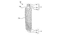
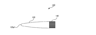
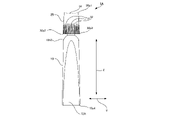
- FIG. 1 is a front view of a fluid container according to a first embodiment of the present invention
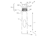
- FIG. FIG. 4 is a front view of the fluid container showing the inner member of the lid in a visible state
- FIG. 4 is a front view of a container body, and an enlarged schematic end view in the longitudinal direction near the boundary between a shoulder portion and a peripheral wall portion of the container
- It is a rear view of a container main body.
- It is a side view of a container main body.
- FIG. 4A is a side view of a container body with auxiliary lines for explanation, and a schematic enlarged view of a concave portion.
- FIG. It is the front view of a container main body, and a schematic end elevation of a orthogonal direction.
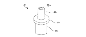
- FIG. 2 is a schematic perspective view of a distal tip;
- Fig. 3 is a schematic end view of the distal tip in the longitudinal direction;
- FIG. 4 is a front view of a state in which the distal tip is connected to the container body;
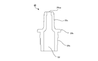
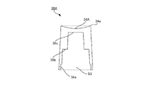
- Fig. 2 is a schematic perspective view of an outer cap;
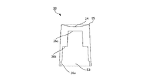
- Fig. 10 is a schematic end view of the outer cap in the longitudinal direction;
- Fig. 2 is a schematic perspective view of an inner cap;
- Fig. 2 is a schematic cross-sectional view of the inner cap in the longitudinal direction;
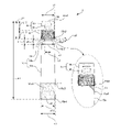
- FIG. 4 is a schematic cross-sectional view of a state in which the outer cap and the inner cap are connected;
- FIG. 17 is a schematic bottom view seen from below (in the direction of arrow X1 in FIG. 16) in a state where the outer cap and the inner cap are connected;
- FIG. 4 is a diagram showing an example of a state in which the fluid container is held with one hand; It is a figure which shows an example of the state which removes a cover body from a container main body. It is a figure which shows an example of the state which takes out the content from a container main body.
- FIG. 4 is a diagram showing forces acting when contents are taken out from a container body;
- FIG. 4 is a diagram showing forces acting when contents are taken out from a container body;
- FIG. 10 is a diagram showing deformation of the concave portion when the contents are taken out from the container body;
- FIG. 10 is a diagram showing a state in which contents are taken out when the contents of the container body become small.
- FIG. 10 is a diagram showing a state in which contents are taken out when the contents of the container body become small. It is a figure which shows an example of the conventional container. It is a figure which shows an example of the conventional container main body.
- FIG. 10 is a diagram showing an example of a state in which a lid is removed from a conventional container body; It is a figure which shows the state which takes out the content from the conventional container main body.
- FIG. 10 is a diagram showing forces acting when contents are taken out from a conventional container body.
- FIG. 10 is a diagram showing forces acting when contents are taken out from a conventional container body.
- FIG. 4 is a front view of a fluid container according to a second embodiment of the present invention
- Fig. 10 is a front view of a fluid container according to a third embodiment of the present invention
- Fig. 2 is a schematic perspective view of an outer cap
- Fig. 10 is a schematic end view of the outer cap in the longitudinal direction;
- the "longitudinal direction” means the longitudinal direction of the container 1 shown in FIG. 1 etc., ie, the direction shown by the arrow Z in FIG.
- a direction orthogonal to the longitudinal direction means a direction orthogonal to the longitudinal direction of the container 1, that is, the direction indicated by arrow V in FIG.
- “Upper” means the direction in which the upper end portion 30p1 of the lid 25 is positioned in the container 1 .
- Downward means the direction in which the lower end portion 10p4 of the container body 10 is positioned in the container 1.
- “Height direction” means the direction indicated by arrow T in the side view of FIG.
- Height means the distance in the height direction from the central axis Z1 in the side view of the container body 10 shown in FIG.
- Low height or “small height” means that the distance is short
- high height or “large height” means that the distance is long.
- the surfaces viewed from the two directions in which the projected area of the container 1 is the largest are defined as “principal surfaces”. That is, the front view of FIG. 3 and the rear view of FIG. 4 show the main surface of the container 1 .
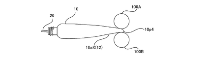
- FIG. 1 An overall configuration of a container 1 according to a first embodiment of the present invention will be described with reference to FIGS. 1 to 8.
- FIG. The container 1 is a cylindrical container and is formed in an elongated shape as a whole.
- the container 1 is composed of a container body 10 and a lid 25 .
- the container body 10 and the lid 25 are detachably engaged.
- Contents are stored in the container body 10 .
- the contents are fluid.
- This fluid includes fluids of various viscosities, including low viscosity fluids such as pure water, and high viscosity fluids, such as gel and jelly.
- the contents are, for example, lotions, milky lotions, beauty essences, and creams such as beauty creams.
- the container 1 is an example of a fluid container.
- the container body 10 is an example of a container body, and the lid 25 is an example of a lid.
- the container 1 is a cosmetics container for storing cosmetics.
- the cosmetic product is, for example, a serum having a suitable viscosity.
- the container 1 is sized in its longitudinal direction so that it can be held with one hand of an average adult woman.
- the length L1 (see FIG. 2) of the container 1 is, for example, 95 millimeters (mm). Let us assume that the average female hand size is defined by hand length, hand width and girth, for example 170 millimeters, 75 millimeters and 180 millimeters respectively. However, unlike the present embodiment, the length L1 of the container 1 is not limited to 95 millimeters, and may be 80 millimeters or more and 110 millimeters or less, for example.
- a concave portion 12 is formed on one main surface of the container body 10 . Between the starting position 10p3 (see FIG. 2) and the lower end portion 10p4 (see FIG. 2), in the side view shown in FIGS. It is configured. Portions of the container body 10 other than the reverse curved peripheral wall portion 10aX are formed in an outwardly convex arc shape. As shown in FIG. 3, the concave portion 12 is formed as a recessed portion in the reverse curved peripheral wall portion 10aX. In the container body 10, the reverse curved peripheral wall portion 10aX is defined as a region closer to the lower end portion 10p4 than the shoulder portion 10b. The height of the recess 12 decreases from the side edges 12a toward the central portion 12b. Also, the height of the concave portion 12 decreases from the starting position 10p3 toward the lower end portion 10p4. In the front view shown in FIG. 3, the side edge portion 12a is formed in a substantially semi-elliptical shape and is open downward.
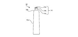
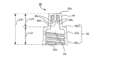
- the lid body 25 is configured in a substantially cylindrical shape whose diameter gradually increases from the upper end portion 30p1 to the lower end portion 30p2.
- the lid 25 is composed of an inner member 40 and an outer member 30 arranged outside the inner member 40 .
- FIG. 1 only the outer member 30 constituting the lid body 25 is shown, and the display of the inner member 40 is omitted.
- the outer member 30 is made of a light-transmissive material
- the inner member 40 is made of a light-impermeable material. Therefore, as shown in FIG. 2 , the inner member 40 can be visually recognized from the outside of the lid 25 through the outer member 30 .
- the outer member 30 is made of G-PET (Glycol-modified PET) in this embodiment, but the light-transmitting material is not limited to G-PET in the present invention.
- the inner member 40 is made of colored PP (polypropylene), but in the present invention, the light-impermeable material is not limited to colored PP.
- Outer member 30 and inner member 40 are formed, for example, by injection molding.
- the external shape of the outer member 30 is cylindrical with a slightly expanding diameter downward. Note that unlike the present embodiment, the external shape of the outer member 30 may be substantially cylindrical. An upper surface 34 of the outer member 30 is formed in a partially spherical shape that is convex downward.
- a plurality of filaments 32 are formed on the outer peripheral wall of the outer member 30 so as to extend from a substantially intermediate position in the longitudinal direction to the lower end portion 30p2.
- the filament 32 has a linear structure that protrudes outward, and serves as an anti-slip to prevent a finger from slipping when the user rotates the lid body 25 with respect to the container body 10. Function.
- the container body 10 is configured to be elastically deformed by an external force. That is, the container body 10 is deformed by an external force, but returns to its original shape when the force is removed.
- the container body 10 is pressed from the outside while the contents are stored in the container body 10, the container body 10 is deformed and the contents are discharged.
- gas usually air
- the shape of the container body 10 returns to its original shape, and at this time, gas (usually air) having the same volume as the volume of the discharged contents enters the container body 10. It's designed to go in. Thereby, the container body 10 can maintain its original shape regardless of the amount of contents stored inside.
- the container body 10 is formed by molding plastic resin.
- the plastic resin is polyethylene resin, more specifically, low-density polyethylene resin, and the molding method is blow molding, but in the present invention, the plastic resin and molding method are limited to these.
- the outer surface of the container main body 10 is subjected to matte processing, which suppresses the smoothness of the surface by providing fine irregularities as the surface processing.
- matte processing suppresses the smoothness of the surface by providing fine irregularities as the surface processing.
- this surface treatment is not visible to the user as the shape of the container body 1, it is used when the user grips the container body 10 and when the user takes out the contents from the container body 10.
- the surface of the user's finger is slightly deformed to fit into the fine irregularities, and is easily fixed at a desired position on the surface of the container body 10, thereby facilitating operation.
- the container body 10 includes a neck portion 14, a main body peripheral wall portion 10a (hereinafter referred to as a "peripheral wall portion 10a"), and a shoulder as a portion connecting the neck portion 14 and the peripheral wall portion 10a. It is composed of a portion 10b.
- the neck portion 14, the peripheral wall portion 10a and the shoulder portion 10b are integrally formed.
- positions in the longitudinal direction of the container body 10 are a connection portion 10p1 where the neck portion 14 and the shoulder portion 10b are connected, an upper end portion 10p2 where the shoulder portion 10b and the peripheral wall portion 10a are connected, and a lower end of the peripheral wall portion 10a.
- the end face of the cross section in the orthogonal direction is substantially circular at the neck 14, the shoulder 10b and the upper end 10p2 of the peripheral wall 10a.
- a region between the starting position 10p3 and the lower end portion 10p4 is a predetermined region in which the concave portion 12 is formed.
- the external shape and the internal space are similar.
- the wall thickness of the peripheral wall portion 10a is 1 millimeter (mm) and the wall thickness of the shoulder portion 10b is also 1 millimeter (mm).
- the thickness of the wall of the peripheral wall portion 10a and the thickness of the wall of the shoulder portion 10b are not limited to the above. Wall thickness may be increased.
- the neck 14 is configured such that both the diameter of the inner diameter and the diameter of the outer diameter are substantially constant over the longitudinal direction, that is, over the top and bottom. That is, the basic shape of the neck portion 14 is a cylindrical shape with a constant diameter.
- the neck portion 14 is configured to be engaged with the lid 25.
- a screw 14b is formed on the outer surface of the neck peripheral wall 14a, and the upper end portion 14c is an open opening.
- a peripheral wall portion 10a of the container body 10 is a closed portion with a closed lower end portion 10p4.
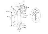
- the outer diameter d2 of the neck portion 14 (the neck peripheral wall 14a in FIG. 3) is smaller than the outer diameter d1 of the lower end portion 30p2 of the lid 25, and the upper end portion 10p2 of the peripheral wall portion 10a. It is formed smaller than the outer diameter d3.
- the diameter d1 of the lower end portion 30p2 of the lid body 25 is substantially the same as the diameter d3 of the upper end portion 10p2 of the peripheral wall portion 10a.
- the outer width w1 of the lower end portion 10p4 of the peripheral wall portion 10a is larger than the diameter d3.
- diameter d1 and diameter d3 are 14.4 millimeters
- diameter d2 is 8.0 millimeters
- width w1 is 19.2 millimeters.
- the diameter d1 of the lower end portion 30p2 of the lid 25 does not have to be substantially the same as the diameter d3 of the upper end portion 10p2 of the peripheral wall portion 10a. There may be a difference of about 10% based on the diameter of one of the two.
- the width of the container body 10 in a front view is maximized near the lower end portion 10p4.
- a tangent line Lc1 of the arc at an intermediate position in the longitudinal direction of the outer shape of the shoulder portion 10b has an angle ⁇ 1 with respect to the orthogonal direction.
- the angle ⁇ 1 is called tangent angle ⁇ 1.
- the tangent angle ⁇ 1 is defined as an acute angle that is equal to or greater than a predetermined minimum angle and equal to or less than a predetermined maximum angle.
- the minimum angle is 30 degrees and the maximum angle is 80 degrees. Desirably, the minimum angle is 40 degrees and the maximum angle is 70 degrees. In this embodiment, the tangent angle ⁇ 1 is 45 degrees.
- FIG. 3 also shows an enlarged schematic end view of the vicinity of the upper end portion 10p2 of the container body 10 in the longitudinal direction.
- the enlarged schematic end view of FIG. 3 is a view of the container body 10 cut vertically along its diameter.
- the outer shape and inner shape of the end face of the cut surface of the shoulder portion 10b in the longitudinal direction are circular arcs.
- the outer shape and inner shape of the end face of the cut surface of the shoulder portion 10b are similar circular arcs.
- a circular arc that is the inner shape of the end surface of the shoulder portion 10b will be described.
- a tangent line Lc2 of the circular arc at an intermediate position in the longitudinal direction of the inner shape of the shoulder portion 10b intersects at an angle ⁇ 2 with a longitudinal tangent line of the inner shape of the cross section near the upper end portion 10p2 of the peripheral wall portion 10a.
- the angle ⁇ 2 is called the tangent angle ⁇ 2.
- the tangential angle ⁇ 2 is an obtuse angle defined as an angle within a predetermined range of 120 degrees or more and 160 degrees or less.
- the tangential angle ⁇ 2 is desirably 130 degrees or more and 150 degrees or less. In this embodiment, the tangent angle ⁇ 2 is 135 degrees.
- the upper end portion 10p2 of the peripheral wall portion 10a and the inner surface of the shoulder portion 10b intersect at an angle larger than the tangential angle ⁇ 2, for example, 170 degrees or more and 180 degrees or less.
- the neck portion 14 is not completely positioned inside the lid body 25 when the container body 10 and the lid body 25 are engaged with each other. That is, a predetermined portion of the neck portion 14 in the longitudinal direction is not positioned inside the lid body 25 and is configured to be exposed to the outside.
- g1 is the length between the lower end 30p2 of the lid 25 and the upper end 10p2 of the peripheral wall 10a
- the connecting portion 10p1 is the length in the longitudinal direction.
- the length between the upper end portion 10p2 (that is, the length of the shoulder portion 10b in the longitudinal direction) is set to g3, and the exposed length of the neck portion 14 is set to g2.
- the length g2 of a predetermined portion of the neck portion 14 exposed to the outside of the lid 25 in the longitudinal direction is defined as a predetermined ratio in relation to the diameter d1 of the lower end portion of the lid 25 (see FIG. 2).
- a predetermined ratio of length g2 to diameter d1 (g2/d1) is defined in the range between 5% and 10%. In this embodiment, as described above, diameter d1 is 14.4 millimeters and length g2 is 1 millimeter.
- a space S1 having a length g1 is formed between the lower end portion 30p2 and the upper end portion 10p2 of the lid 25 by being exposed to the outside.
- length g1 is 5 millimeters. The inventors of the present invention found that if the tangential angle ⁇ 1 is too small, the space S1 of sufficient length and width is not created, and the lid 25 is sandwiched when the lid 25 is removed from the container body 10 as described later.
- the tangential angle .theta.1 is defined as a range in which such problems are unlikely to occur as a result of trial and error.
- the length g2 is defined as a length that, as a result of trial and error, can further reduce the possibility of such problems occurring. That is, by configuring the lengths g1 to g3 and the tangential angle ⁇ 1 as described above, it is possible to reduce the possibility that the fingers that turn the lid 25 will come into contact with the container body 10, and the lid 25 can be removed efficiently.
- a space S1 can be formed for this purpose.
- the end face of the cut surface of the container body 10 in the orthogonal direction is substantially circular at the neck 14, the shoulder 10b, and the upper end 10p2, which is the portion of the peripheral wall 10a that connects with the shoulder 10b.
- the end faces of the cross section of the container body 10 in the orthogonal direction are a schematic end view on the AA line, a schematic end view on the BB line, and a schematic end view on the CC line.
- DD line schematic end view, EE line schematic end view, FF line schematic end view, and GG line schematic end view it is formed in a circular or elliptical shape convex outward and approaches the lower end portion 10p4.
- the reverse curved peripheral wall portion 10aX and the concave portion 12 exist between the starting position 10p3 and the lower end portion 10p4, so the end face is not a simple elliptical shape.
- the concave portion 12 is formed in a predetermined area of the peripheral wall portion 10a.
- the predetermined region of the peripheral wall portion 10a in which the concave portion 12 is formed is a region on at least one of the two main surfaces of the peripheral wall portion 10a.
- the predetermined region where the concave portion 12 is formed is defined as a region closer to the lower end portion 10p4 than the shoulder portion 10b in the longitudinal direction of the peripheral wall portion 10a. In this embodiment, as shown in FIG.
- the concave portion 12 is formed in a region between the starting position 10p3 and the lower end portion 10p4.
- the area of the main surface including the concave portion 12 is configured as a reverse curved peripheral wall portion 10aX that is arcuately convex toward the inside of the container body 10 in a side view. That is, the reverse curved peripheral wall portion 10aX is formed in the region between the starting position 10p3 and the lower end portion 10p4, and the recessed portion 12 is the recessed portion of the reverse curved peripheral wall portion 10aX.
- the outer shape 10aL of the left side peripheral wall portion 10a and the outer shape 10aR of the right side peripheral wall portion 10a are not bilaterally symmetrical. If the outer shape 10aL is symmetrical with the outer shape 10aR, it becomes a virtual outer shape 10aS indicated by a dotted line. That is, the reverse curved peripheral wall portion 10aX causes a difference between the virtual outer shape 10aS and the outer shape 10aL.
- the container body 10 has a substantially bilaterally symmetrical shape, but as shown in FIG. , the container body 10 is configured to have a left-right asymmetrical shape with respect to the central axis Z1 in a side view. This asymmetrical shape is visible to the user, and thus attracts the user's attention.
- the height of the reverse curved peripheral wall portion 10aX is lower than the right peripheral wall portion 10aR at the corresponding position in the longitudinal direction.
- the height of the corresponding position of the concave portion 12 is lower than the height of the reverse curved peripheral wall portion 10aX, and is the lowest at the central portion 12b.
- the portions other than the recessed portion 12 are configured as convex portions whose end surfaces of cross-sectional surfaces in the orthogonal direction are outwardly convex.
- the portions other than the reverse curved peripheral wall portion 10aX are outwardly convex as can be understood from the schematic end view on line AA, the schematic end view on line BB, and the schematic end view on line CC, for example. It is formed in a curved shape.
- the reverse curved peripheral wall portion 10aX is formed, for example, as can be understood from the schematic end view on the DD line, the schematic end view on the EE line, the schematic end view on the FF line, and the schematic end view on the GG line in FIG.
- the main surface has an outwardly convex curved surface shape
- the other main surface has an inwardly convex curved surface shape.
- the distance between the inner surface of the central portion 12b of the concave portion 12 and the corresponding position of the inner surface of the lower main surface in the orthogonal direction is the distance h1 in the CC line schematic end view and the DD line schematic end view.
- the distance is h2
- the distance is h3 in the EE line schematic end view
- the distance is h4 in the FF line schematic end view
- the distance is h5 in the GG line schematic end view.
- the distances between these inner surfaces are in the relation of the formula: "h1>h2>h3>h4>h5".
- the distance between the inner surfaces is also a size that allows the container body 10 to deform when a force directed from the outside to the inside is applied to the two main surfaces of the container body 10 corresponding to each other in the longitudinal direction.
- the distance between the inner surfaces becomes shorter as the lower end portion 10p4 is approached. This means that the container body 10 has less room to deform in the height direction as it approaches the lower end portion 10p4.
- the formation of the concave portion 12 reduces the room for deformation in the height direction as the lower end portion 10p4 is approached.
- this configuration of the recessed portion 12 facilitates proper discharge when the container body 10 is relatively overfilled, and also allows the stored contents of the container body 10 to be displaced relative to each other. It makes it possible to facilitate the discharge of an appropriate amount even when the amount is relatively small.
- the difference between the virtual outline 10aS and the portion where the height of the central portion 12b of the concave portion 12 is the most different, that is, the maximum depth md1 of the concave portion 12 is defined between 0.7 mm and 3.5 mm, Desirably, it is defined between 1.0 millimeters and 3.0 millimeters, and in this embodiment is 1.8 millimeters.
- the size of the concave portion 12 in the longitudinal direction and in the orthogonal direction is defined as a size that can be contacted by the user's finger.
- the maximum width w12 (see FIG. 2) of the recessed portion 12 is set to be equal to or more than half the width w1 of the lower end portion 10p4 and equal to or less than the width w1 of the lower end portion 10p4.
- the maximum width w12 is smaller than the width w1 of the lower end portion 10p4 by the thickness of the peripheral wall portion 10a. That is, the maximum width w12 of the recessed portion 12 is limited by the thickness of the peripheral wall portion 10a, but is configured as the maximum possible width in terms of the structure of the container body 10. As shown in FIG.
- the maximum width of the concave portion 12 may be defined as a width that is two-thirds or more of the width w1 of the lower end portion 10p4 and less than or equal to the width w1.
- the longitudinal dimension of the concave portion 12, that is, the distance L3 (see FIG. 6) between the starting position 10p3 and the lower end portion 10p4 is, for example, 18 millimeters, as will be described later.
- the recessed portion 12 is formed so that, in plan view, the width of the main surface of the recessed portion 12 increases from a position corresponding to the starting position 10p3 of the recessed portion 12 in the longitudinal direction toward the lower end portion 10p4.
- the concave portion 12 is formed in a substantially semi-elliptical shape in plan view on the main surface, and in the longitudinal direction, the upper portion corresponding to the start position 10p3 is closed and the lower portion is open.
- the length L2 of the peripheral wall portion 10a in the longitudinal direction is the length L3 of the area where the concave portion 12 is formed, and the length L4 of the portion where the concave portion 12 is not formed.
- the length L3 is smaller than the length L4 in this embodiment.
- length L3 is 18 millimeters and length L4 is 52 millimeters.
- the maximum width of the concave portion 12 is the width at the lower end portion 10p4, which is, for example, 17 millimeters.
- the length, width, and depth md1 of the concave portion 12 are designed to minimize the degree of reduction in the volume of the container body 10 while preventing excessive discharge of the contents by the concave portion 12. This range was found as a result of trial and error.
- the tip 20 has a base portion 20a, an enlarged diameter portion 20b and a tip portion 20c. As shown in FIG. 10, the distal tip 20 is formed in a hollow structure with upper and lower openings, and has a space S2.
- the distal tip 20 is connected to the container body 10.
- the container body 10 When the container body 10 is pressed from the outside while the contents are stored in the container body 10, the contents pass through the space S2 of the tip 20 and are discharged from the open end 20ca of the tip 20c. .
- the outer member 30 is formed in a columnar shape whose diameter increases from the top to the bottom, and the inner side is a space S3 that is open at the bottom. As described above, the outer member 30 is made of a material having optical transparency.
- An upper surface 34 of the outer member 30 is formed in a partially spherical shape that is convex downward.
- An annular flat portion 35 having a flat upper surface is formed around the upper surface 34 .
- the upper surface 34 and the annular flat portion 35 are used as the upper surface portion of the outer member 30, and the upper surface 34, which is a part of the upper surface portion, has a partially spherical shape convex downward. good.
- the filaments 32 are formed over the length L12.
- the filaments 32 are not formed in the length L13 portion above the outer member 30 in the longitudinal direction.
- inner member 40 has a base portion 42 and a tip portion 44 .
- the outer shape of the base portion 42 and the tip portion 44 is substantially cylindrical, and the diameter becomes slightly smaller toward the top.
- the maximum diameter of the outer shape of the tip portion 44 is smaller than the minimum diameter of the outer shape of the base portion 42 (hereinafter referred to as "diameter condition").
- L22 is longer than L23.
- L22 is substantially the same length as, or slightly shorter than, length L12 (see FIG. 2) of filaments 32 of outer member 30 .
- the inner side of the inner member 40 forms a space S4 with an open bottom.
- a screw 42e is formed inside the base 42.
- the screw 42e engages with the screw 14b (see FIG. 3, etc.) of the neck portion 14 of the container body 10 when the container body 10 and the lid body 25 are engaged with each other.
- a center projection 44 b is formed at the center of the inner ceiling surface of the tip portion 44 .
- the center protrusion 44b is inserted from the open end 20ca of the tip 20 (see FIG. 9) into the tip 20c to seal the open end 20ca when the container body 10 and the lid 25 are engaged with each other.
- a plurality of ridges 44 c are formed on the inner peripheral wall of the tip portion 44 .
- the projection 44c guides and positions the front end 20c of the front tip 20 (see FIG. 9) when the container body 10 and the lid 25 are engaged, and ensures that the center projection 44b moves from the open end 20ca to the front end. It is inserted into portion 20c and assists in sealing open end 20ca.
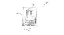
- the outer member 30 is arranged outside the inner member 40 to form the lid body 25 .
- the cover 25 of FIG. 16 is viewed from below indicated by an arrow X1
- the view shown in FIG. 17 is obtained.
- the shoulder portion 42d (see FIG. 15) of the inner member 40 contacts the intermediate ceiling surface 36b (see FIG. 13) of the outer member 30, and the enlarged diameter portion 42c (see FIG. 15) of the inner member 40 abuts on the bottom enlarged diameter portion 36a (see FIG. 13).
- a protruding portion 42b see FIG.
- the filars 32 of the outer member 30 are positioned outside the peripheral wall of the base 42 of the inner member 40 and at the distal end 44 . It is substantially not arranged outside the peripheral wall.
- the striations 32 are relatively visible to the user because the inner member 40 is made of a non-light-transmitting material compared to when the inner member 40 is made of a light-transmitting material. is easily configured. Furthermore, since the distance between the filament 32 and the peripheral wall of the base 42 is smaller by satisfying the diameter condition than when the diameter condition is not met, the filament 32 is relatively visually recognized by the user. has become easier.
- the tip portion 44 of the inner member 40 can be relatively clearly seen through the outer member 30. . Furthermore, by satisfying the diameter condition, the distance between the portion of the outer member 30 where the filaments 32 are not formed and the outer circumference of the tip portion 44 is greater than when the diameter condition is not satisfied. Through the portion of 30 where the filament 32 is not formed, the distal end portion 44 is configured to be more clearly visible from the outside.
- the filament 32 of the outer member 30 and the tip portion 44 of the inner member 40 are easily visible from the outside.
- the reverse curved peripheral wall portion 10aX functions as a structure for guiding the user's consciousness to the recessed portion 12 more reliably and bringing the finger into contact with the recessed portion 12 more reliably.
- the user is less likely to drop the container 1, and the user's mental state can be prevented from becoming unstable.
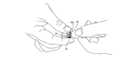
- the upper surface 34 is configured in a partially spherical shape and the concave portion 12 is formed, so that the container 1 can be gripped so as to be pinched.
- the lid 25 When removing the lid 25 from the container body 10, for example, as shown in FIG. 32 is gripped with two fingers and rotated. At this time, since the space S1 (see FIG. 2) exists between the main body peripheral wall portion 10a and the lid 25, the fingers of the right hand touch only the ridges 32 and do not touch the main body peripheral wall portion 10a. As a result, it is possible to avoid the friction caused by the fingers of the right hand coming into contact with the main body peripheral wall portion 10a. That is, the space S1 functions as friction avoidance means for avoiding unnecessary friction. As described above, the user of the container 1 can effectively grasp the container 1 and remove the lid 25 from the container body 10 before taking out the contents from the container body 10 . As a result, negative emotions such as anger and impatience do not occur, and a stable mental state can be maintained. This completes the preparation for carrying out a delicate finger operation when taking out the contents from the container main body 10 .
- the lid 25 removed from the container body 10 can be placed on a flat placement place such as a desk (not shown) with the upper surface 34 facing downward, for example.
- a flat placement place such as a desk (not shown) with the upper surface 34 facing downward, for example.
- the annular flat portion 35 comes into contact with the placement location, and the lid body 25 is placed stably.
- the container body 10 and the lid body 25 can be engaged with each other after the container body 10 is used. After that, it is sufficient to remove dirt from only the annular flat portion 35 of the lid body 25 .
- FIG. 21 and 22 are side views of the container body 10, the reverse curved peripheral wall portion 10aX is visible, and the concave portion 12 is not visible.
- the reference numerals of the concave portions 12 are also shown. This also applies to FIGS. 24 and 25.
- FIG. 21 and 22 are side views of the container body 10, the reverse curved peripheral wall portion 10aX is visible, and the concave portion 12 is not visible.
- the reference numerals of the concave portions 12 are also shown. This also applies to FIGS. 24 and 25.
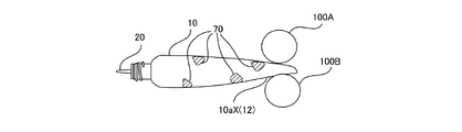
- the container main body 10 stores a relatively large amount of contents. For example, it is 70% or more of the volume of the container body 10 .
- This state is called a "filled state".
- reference numerals 100A and 100B represent fingers of the user.
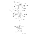
- a force is applied so as to sandwich the container body 10 between the fingers 100A and 100B.
- the force represented by the vector v1 acts on the content 70, and the content 70 is ejected from the tip 20.
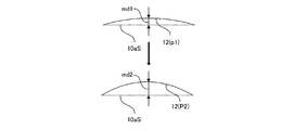
- the extent to which the force applied to the flowing contents 70 varies is relatively small. That is, the contents are ejected without a significant change in the direction and magnitude of the force applied by the user. This reduces the possibility that the content 70 will be excessively ejected from the distal tip 20 . Further, at this time, as shown in FIG. 23, the depth md1 of the concave portion 12 (degree of concave with respect to the imaginary outer shape 10aS) increases to a depth md2.
- the concave portion 12 is deformed, the direction of the concave shape does not change, and the depth only increases from md1 to md2. That is, the concave portion 12 does not undergo a sudden and large shape change. This further reduces the possibility that the content 70 is excessively discharged from the tip 20 .
- the container body 10 has less room for deformation in the height direction at a position closer to the lower end portion 10p4 due to the concave portion 12 being formed. .
- the portion near the lower end portion 10p4 of the concave portion 12 there is a possibility that the content 70 will be expelled excessively from the distal tip 20 compared to pressing other portions of the container body 10. is reduced. This is because the portion near the lower end portion 10p4 is configured as a portion of the container body 10 that has the least room for deformation even if the force from the outside is excessive.
- the container body 10 When the amount of the contents 70 stored in the container main body 10 decreases, pressing the portion near the lower end 10p4 discharges a smaller amount of the contents 70 than the appropriate amount. to press the upper part. Even in this case, the container body 10 has less room for deformation in the height direction due to the formation of the concave portion 12, compared to the case where the concave portion 12 is not present. The possibility that the contents 70 are excessively ejected from the distal tip 20 is reduced.
- the above-mentioned effect becomes more remarkable by forming the concave portion 12 on the reverse curved peripheral wall portion 10aX.
- a concave portion having the same room for deformation in the height direction as in the present embodiment (hereinafter referred to as a “temporary concave portion”) is formed. Then, at the end face of the cut surface in the orthogonal direction, the height difference between the side edge portion and the central portion of the temporary concave portion 12 is greater than the height difference between the side edge portion 12a and the central portion 12b of the concave portion 12 of the present embodiment. The difference in height becomes large.
- the rough end face shape of the pad side of the finger is an arc shape corresponding to the long axis of an ellipse, and the height H is greater than the width W. is low.
- the ratio of maximum height to maximum width (H/W) is larger than that of the concave portion 12.
- the recessed portion 12 is formed in the reverse curved peripheral wall portion 10aX, even if the ratio of maximum height to maximum width (H/W) is smaller than that of the provisional recessed portion, the height It is possible to reduce the room for deformation in the vertical direction. It should be noted that the above is an explanation of the advantageous effects of this embodiment, and does not exclude the provisional concave portion from the present invention.
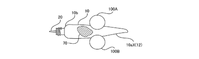
- the 24 and 25 show a case where the content 70 stored in the container 1 is small.
- the case where the content 70 becomes small is, for example, the case where the amount of the content 70 becomes 30% or less of the volume of the container body 10 .
- This state is called a "small amount state".
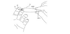
- the small amount state especially when the contents 70 are gel-like, the contents 70 are not concentrated in one place in the container main body 10, but are dispersed in a plurality of positions as shown in FIG. likely to be. Therefore, it is necessary to collect the dispersed contents 70 and then push them out. Also in this case, when taking out the contents 70 from the container main body 10, first, as shown in FIG. , and the concave portion 12 in the longitudinal direction.
- a force is applied so that the container body 10 is sandwiched between the fingers 100A and 100B, and the fingers 100A and 100B are moved while sliding toward the shoulder portion 10b. That is, in the container body 10, a force is applied to gather the dispersed contents 70 and guide them in the direction of the shoulder portion 10b. At this time, it is difficult to apply only the force directed toward the shoulder portion 10b to the contents 70, and the force directed in the opposite direction is also applied.
- the container body 10 is formed in a shape that flattens toward the bottom, the reverse curved peripheral wall portion 10aX is formed, and the concave portion 12 is formed in the reverse curved peripheral wall portion 10aX.
- the resistance of the contents 70 towards the bottom is greater than towards the shoulder 10b. Therefore, it is difficult for the contents 70 to face toward the bottom of the container body 10 .
- the formation of the concave portion 12 in the container body 10 reduces the possibility that the content 70 is excessively discharged from the tip 20 .
- the force that presses the container body 10 is greater than in the full state. Therefore, the closer the position is to the lower end portion 10p4, the smaller the room for deformation in the height direction. Therefore, even if a relatively large force is applied in the initial stage of force application, there is little room for the container body 10 to change in the height direction. less likely to be ejected.
- FIG. 1 An example of a conventional container 110 will be described with reference to FIGS. 26 to 32.
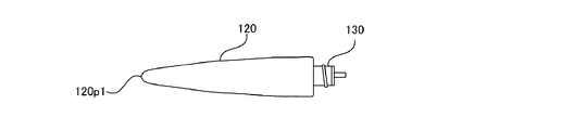
- the container 110 is composed of a main body 120 and a lid 140.
- the main body 120 is configured in a shape convex outward along the entire longitudinal direction, and the cross section of the portion connected to the lid body 140 is substantially circular, and the degree of flatness increases toward the end portion 120p1. Become.
- a distal tip 130 is connected to the main body 120 .
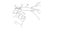
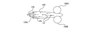
- reference numerals 100A and 100B represent fingers of the user.
- the fingers 100A and 100B are pressed so as to sandwich the container body 120.
- a force represented by vector v2 acts on contents 70, and furthermore, the contents 70 come into contact with the inner side of shoulder 120b and change direction significantly as represented by vector v2a.
- the extent to which the force applied to the contents during flow fluctuates is relatively large. This increases the possibility that the contents will be expelled excessively from the distal tip 130 . Further, at this time, as shown in FIG.
- the outwardly projecting shape of the container body 120 is deformed into an inwardly projecting shape. That is, the convex depth (degree of convexity with respect to the plane) k1 is the depth -k2. In this way, the rapid and large deformation of the container body 120 increases the possibility that the contents will be excessively discharged.
- ⁇ Second embodiment> A second embodiment will be described with reference to FIG. The description of matters common to the first embodiment is omitted.
- a concave portion 12A is formed over substantially the entire longitudinal direction of the container body 10. As shown in FIG.
- the concave portion 12A of the container 1A has a larger area than the concave portion 12 of the container 1 of the first embodiment, the volume of the container 1A is smaller than the volume of the container 1 if other conditions are the same. However, in the container 1A, even when the remaining amount of the contents is low, by pressing the concave portion 12A, the contents can be used completely while preventing excessive discharge of the contents. be able to.
- a third embodiment will be described with reference to FIG. The description of matters common to the first embodiment is omitted.
- the main surface of the container body 10 is formed with a concave portion 12B having an elliptical shape in plan view.
- the upper surface 34A of the outer member 30A of the lid 25A continues to the end, and the end forms an annular end 34a. That is, unlike the first embodiment, the annular flat portion 35 does not exist.
- the entire upper surface portion is an upper surface 34A having a partially spherical surface convex downward.
- the lid 25A removed from the container body 10 can be placed on a flat place such as a desk (not shown) with the top surface 34A facing downward. As a result, the annular end portion 34a abuts on the placement location, and the lid body 25 is placed stably.
- the container body 10 can be engaged with the lid 25A after the container body 10 is used. After that, the dirt can be removed only from the annular end portion 34a of the lid 25A.
- the fluid container of the present invention is not limited to the above embodiment, and various modifications can be made without departing from the gist of the present invention. Moreover, each of the above-described embodiments can be appropriately combined as long as there is no technical contradiction.
- the concave portions 12, 12A and 12B may be formed not only on one principal surface but also on both principal surfaces.
Landscapes
- Engineering & Computer Science (AREA)
- Mechanical Engineering (AREA)
- Closures For Containers (AREA)
Abstract
本発明は、内容物が過剰に押し出される可能性を低減する流体用容器を提供するものである。本発明の流体用容器1は、本体周壁部10aにおいて、投影面積が最も大きくなる2つの方向を主面と定義するとき、内側に向かって凸の曲面形状である凹状部12が少なくともいずれか一方の主面に形成され、凹状部12は、主面において長手方向の上方から下方に向かって幅が広くなるように形成される。
Description
本発明は流体である内容物を格納する流体用容器に関する。
従来、液状の内容物または粘度がやや高いゲル状の内容物を格納する樹脂製のチューブ状容器が知られている(例えば、特許文献1)。
弾性変形可能なチューブ状容器は、内容物の残量に関わらず、当初の形状を維持することができる。本発明は、このようなチューブ状容器であって、全体として細長い形状をしており、平均的な成人女性が片手で保持できる程度の大きさのものを対象とする。使用者がこのようなチューブ状容器から内容物を取り出すときには、チューブ状容器の容器本体の胴体部分を指で挟んで押圧し、その圧力によって内容物を押し出す。このとき、チューブ状容器から、内容物が、1回の使用のための適量よりも多く、過剰に押し出される場合がある。
本発明は、上記を踏まえて、内容物が過剰に押し出される可能性を低減する流体用容器を提供するものである。
第一の発明は、流体である内容物を格納する流体用容器であって、前記流体用容器は、前記内容物を格納する容器本体と、前記容器本体と着脱可能に係合する蓋体を有し、前記容器本体は、外部からの力によって弾性変形するように構成されており、長手方向の全体にわたって直径が実質的に一定であって、前記蓋体と係合するための首部と、下端部が閉鎖部となっている本体周壁部と、前記首部と前記本体周壁部とを接続する肩部と、から構成され、前記流体用容器の長手方向と直交する方向である直交方向における切断面の端面は、前記首部、前記肩部、及び、前記肩部と接続する前記本体周壁部の部分において、実質的に円形であり、前記本体周壁部は、全体的な形状として、前記直交方向の切断面の端面が外側に向かって凸の円形または楕円形状に形成され、かつ、前記端面は前記本体周壁部の下端部に近づくほど扁平に形成され、部分的な形状として、前記本体周壁部において、投影面積が最も大きくなる2つの方向から視た面を主面と定義するとき、前記直交方向の切断面の端面が内側に向かって凸の曲面形状である凹状部が少なくともいずれか一方の前記主面の所定領域内に形成され、前記凹状部は、前記主面において前記長手方向における前記凹状部の開始位置から前記本体周壁部の前記下端部に向かって幅が広くなっていくように形成されており、前記凹状部の最大幅は、前記本体周壁部の下端部の幅の2分の1以上であって、前記本体周壁部の下端部の幅以下において規定される、流体用容器である。
従来、流体用容器の容器本体の周壁について、長手方向に直交する切断面の端面は外側に凸状の曲面に形成されている。これにより、容器本体の容積が大きくなる。また、容器本体の内側からの圧力に対する機械的強度が強くなる。本発明の発明者は、従来の弾性変形可能な流体用容器から内容物が排出されるときに、容器の周壁が押圧されることによって、凸状の曲面が内側に凸状の曲面に変形する現象に着目し、内容物である流体が過剰に押し出される現象の要因は、凸状の方向が反対側になることを含む周壁の急激かつ大きな形状変化であることを発見した。本発明の発明者は、この発見に基づいて、容器本体を押圧して内容物を取り出すときに、周壁の急激かつ大きな形状変化を低減させるという技術思想に想到した。そして、本発明の発明者は、その技術思想の具体化として、流体用容器の容積をあえて犠牲にして、本体周壁部において、投影面積が最も大きくなる2つの面を主面とするとき、少なくともいずれか一方の主面に内側に向かって凸の凹状部を形成するという第一の発明の構成に想到した。容器本体の主面の一部を凹状部として構成すると、容器本体の内部から内容物を取り出すときに、凹状部に指を当接させて、凹状部を押圧することができる。これにより、容器本体に凹状部が存在しない場合に比べて、内容物である流体が過剰に流出する現象の発生確率は低減した。これは、容器本体に凹状部を形成しない場合に比べて、凹状部を形成した場合には、凹状部において、容器本体が押圧によって変形できる余地が小さいという事実が一つの要因と考えられる。また、凹状部が押圧されると、容器本体の変形は、凹状の程度が大きくなるだけであり、凹状の方向は変化がないから、凹状部が存在しない場合に比べて、周壁の急激かつ大きな形状変化は生じないという事実がもう一つの要因であると考えられる。凹状部の存在によって、容器本体の容積は犠牲になるが、内容物が過剰に押し出される可能性が低減するから、実際に使用者によって使用される内容物の量は凹状部による容積減少ほどには低減せず、場合によっては、むしろ増加する。以上のように、第一の発明の構成によれば、内容物が過剰に押し出される可能性を低減することができる。
第二の発明は、第一の発明の構成において、前記本体周壁部は、側面視において、全体的な形状として、外側に向かって凸の円弧状に形成されており、部分的な形状として、内側に向かって凸の円弧状に形成された逆湾曲周壁部が形成されており、前記凹状部が形成される前記所定領域は、前記逆湾曲周壁部である、流体用容器である。
第二の発明の構成によれば、逆湾曲周壁部は、容器本体において、側面視における凸の方向が他の部分とは反対であるから、指を当接させる位置として、使用者に容易に認識され得る。そして、凹状部は逆湾曲周壁部内に形成されるから、やはり、使用者に容易に認識され得る。これにより、使用者が凹状部を利用する可能性が高くなるから、内容物が過剰に押し出される可能性を低減することができる。
第三の発明は、第二の発明の構成において、前記逆湾曲周壁部において、前記凹状部以外の部分は、前記直交方向の切断面の端面が外側に向かって凸の凸状部として構成されている、流体用容器である。
第三の発明の構成によれば、逆湾曲周壁部において、凹状部とそれ以外の部分において、凸の方向が反対方向である。これにより、逆湾曲周壁部において、凹状部とそれ以外の部分の凸の方向が同じ方向である場合に比べて、逆湾曲周壁部の機械的強度を大きくすることができる。
第四の発明は、第一の発明乃至第三の発明のいずれかの構成において、前記所定領域は、前記主面において、前記肩部よりも前記下端部に近い領域として規定されている、流体用容器である。
本発明の流体用容器は、全体的な形状として、直交方向における切断面の端面は、下端部に近づくほど扁平に形成されているから、本体周壁部の外側から直交方向の力を加えたときに、肩部近傍よりも下端部近傍の方が変形する余地が小さい。このため、凹状部を肩部よりも下端部に近い領域に形成することによって、内容物が過剰に押し出される可能性を一層低減することができる。
第五の発明は、第一の発明乃至第四の発明のいずれかの構成において、前記蓋体は、内側部材と、前記内側部材の外側に配置される外側部材とから構成され、前記外側部材は光透過性の材料で形成され、前記内側部材は光不透過性の材料で形成され、前記蓋体の外部から、前記外側部材を通して前記内側部材が視認可能に構成されており、前記外側部材の上面は、下方に向かって凸の部分球面状に形成されている、請求項1乃至請求項4のいずれかに記載の流体用容器である。
使用者は、流体用容器から蓋体を外し、次いで、容器本体から内容物を取り出す。本発明の発明者は、蓋体を把持する動作、及び、蓋を外す動作にも着目した。蓋体は比較的小さい部品であるため、例えば、蓋を外す動作の途中や、蓋体を外した後、机など平坦な場所に置く動作の中で、転がって床などに落下するなどの不都合な状況が生じる場合がある。使用者が、次の段階である内容物を出す動作へとスムーズに移行するためには、より確実に蓋を把持し、上述の不都合な状況を回避する必要がある。この点、第五の発明の構成によれば、使用者は、流体用容器を把持するときに、部分球面状に形成された外側部材の上面に指を固定することができる。さらに、外側部材を通して内側部材が視認可能であるから、使用者の視点を外側部材の内側に位置する内側部材に向かわせることによって、外部部材の内側に配置されている内側部材を把持する意識を生じさせることができるから、外側部材が不透明である場合に比べて、より確実に外側部材を把持させることができる。これにより、上述の不都合な状況が生じる可能性が低減する。また、流体用容器が、人の手で把持できる程度の大きさに構成されている場合には、例えば、1つの指を蓋体の上面に固定し、もう一つの指を容器本体の凹状部に固定することによって、流体用容器を二本の指で挟みつけるようにして確実に把持することができる。さらに、容器本体から蓋体を外したときに、蓋体の上面を下方に向けて載置することによって、上面における部分球面状の周縁部のみが載置場所と接するから、載置場所が汚れていた場合であっても、容器本体の使用後に、蓋体を容器本体に係合させて、蓋体の上面の周縁部のみを清潔にすることで、蓋体を清潔に維持することができる。さらに、本発明の発明者は、流体用容器から内容物を適量だけ取り出すためには、比較的小さい力で、内容物を徐々に出すことが、重量な要素だと考えた。ところが、上述の不都合な状況が生じると、落下した蓋を探して、拾うなど予定外の動作が増え、その心理的な影響により、次の工程である流体用容器から内容物を取り出すときに、過剰な力で容器本体を押圧し、内容物が過剰に吐出されてしまう現象が生じる可能性が高くなる。この点、本発明の構成によれば、蓋体を把持する動作、蓋を外す動作、及び、蓋を載置する動作がスムーズに進行する可能性が高いから、内容物を適量だけ吐出できる可能性が高くなる。
第六の発明は、第五の発明の構成において、前記外側部材の外形は、実質的に円柱、または、下方に向かって拡径する円柱状であり、前記蓋体の前記外側部材の外側の周壁には、前記長手方向に延在する複数の線条が形成されており、前記内側部材は、基部と、前記基部の上方に配置される先端部から形成されており、前記先端部の最大の直径は、前記基部の最小の直径よりも小さく、前記線条は、実質的に、前記基部に対応する位置に形成され、前記先端部に対応する位置には形成されていない、流体用容器である。
第六の発明の構成によれば、内側部材の外側に外側部材が配置されたときに、外側部材線条は、内側部材の基部の周壁の外側に配置され、先端部の周壁の外側には実質的に配置されない。線条は、内側部材も外側部材と同様の光透過性の材料で形成されている場合に比べて、内側部材が光不透過性の材料で形成されていることによって、使用者にとって、相対的に視認が容易な構成となっている。さらに、先端部の外形の最大の直径が基部の外形の最小の直径よりも小さくない場合に比べて、先端部の外形の最大の直径が基部の外形の最小の直径よりも小さいこと(以下、「直径条件」と呼ぶ。)によって、基部の外周と線条との距離が小さくなっているから、線条は、使用者にとって、視認が一層容易になっている。また、線条が、先端部の周壁の外側には実質的に配置されないことによって、使用者は、内側部材の先端部を相対的に明確に視認することができるように構成されている。さらに、直径条件を満たさない場合に比べて、直径条件を満たすことによって、先端部の外周と外側部材の外周との距離が大きくなっているから、外側部材において線条が形成されていない部分を通して、先端部が一層明確に視認されるように構成されている。上述のように、内側部材及び外側部材は、互いに係合したときに、外側部材の線条と内側部材の先端部が外側から視認され易い構成となっている。これにより、使用者は、流体用容器を把持するときに、蓋体の内側部材を意識して、より確実に流体用容器を把持することができる。また、使用者が、容器本体から蓋体を外すときに、相対的に容易に線条を認識して指を線条に当接させることができる。
第七の発明は、第一の発明乃至第六の発明のいずれかの構成において前記首部の直径は、前記蓋体の下端部の直径よりも小さく、かつ、前記本体周壁部の上端部の直径よりも小さく形成され、前記長手方向における前記肩部の切断面の端面の外形は円弧であり、前記長手方向における前記円弧の中間位置における前記円弧の接線の前記直交方向に対する角度である接線角度は、所定の最小角度以上であり、かつ、所定の最大角度以下の鋭角であり、前記最小角度は30度であり、前記最大角度は80度である、流体用容器である。
第七の発明の構成によれば、蓋体の下端部と本体周壁部の上端部の直径よりも、首部の直径が小さく構成されており、肩部の外形が円弧であり、長手方向における中間位置における円弧の接線角度は直交方向に対して30度以上80度以下に規定されているから、その角度が30度よりも小さい場合に比べて、蓋体と本体周壁部との間に大きな隙間が生じる。このため、使用者が蓋体の下端部近傍を指で把持して容器本体に対して相対的に回動させて蓋体を外すとき、蓋体を把持する使用者の指が容器本体と接することはないか、接する面積が相対的に小さくなる。これは、蓋体の取り外しには影響しない無駄な摩擦が使用者の指に作用する程度が低減することを意味する。これにより、使用者はより効果的に蓋体を本体から外すことができる。
第八の発明は、第七の発明の構成において、前記容器本体と前記蓋体とが係合した状態において、前記長手方向における前記首部の所定部分は前記蓋体の内側には位置せず、前記蓋体の外部に露出するように構成されており、前記長手方向において前記首部の前記所定部分が前記蓋体の外部の露出する程度は、前記蓋体の下端部の直径との関係で規定される、流体用容器である。
第八の発明の構成によれば、容器本体と蓋体とが係合した状態において、長手方向における首部の全体が外部に露出しないように構成されている場合に比べて、蓋体の下端部と本体周壁部の上端部との間に一層大きな隙間が生じる。そして、その首部が露出する程度は、前記蓋体の下端部の直径との関係で規定される。これは、蓋体を外すときに、使用者の指は、本体周壁部と接しにくくなり、使用者の指に作用する無駄な摩擦が一層低減することを意味する。これにより、使用者はより一層効果的に蓋体を本体から外すことができる。このため、より一層、内容物を過剰に流出させる可能性を低減することができる。
第九の発明は、第一の発明乃至第八の発明のいずれかの構成において、前記長手方向における前記肩部の切断面の端面の内形は円弧であり、前記肩部の内形における長手方向の中間位置における円弧の接線と、前記本体周壁部が前記肩部と接続する部分の前記本体周壁部の断面の内形の前記長手方向の接線とは鈍角で交わり、前記鈍角は、120度以上160度以下において規定される所定範囲内の角度として規定される、流体用容器である。
第九の発明の構成によれば、容器本体に格納された内容物が下方から肩部方向へ移動するとき、長手方向において肩部と本体周壁部が直角に近い場合に比べて、移動方向を大きく変えることはない。このため、流動中の内容物に加わる力が変動する程度は相対的に小さい。すなわち、使用者によって加えられた力の方向及び大きさが大きく変わることなく内容物が押し出される。これにより、内容物が過剰に押し出される可能性は低減する。
本発明にかかる液体容器によれば、内容物が過剰に押し出される可能性を低減する流体用容器を提供することができる。
以下、図面に基づき本発明の好適な実施形態を説明する。なお、当業者が適宜実施できる構成については説明を省略し、本発明の基本的な構成についてのみ説明する。
<第一の実施形態>
本発明の実施形態について以下図面を参照して説明する。なお、本明細書において、「長手方向」は、図1等示す容器1の長手方向、すなわち、図1の矢印Zに示す方向を意味する。また、「長手方向に直交する方向」は、容器1の長手方向に直交する方向、すなわち、図1の矢印Vに示す方向を意味する。「上方」とは、容器1において、蓋体25の上端部30p1が位置する方向を意味する。「下方」とは、容器1において、容器本体10の下端部10p4が位置する方向を意味する。「高さ方向」とは、図6に示す側面図における矢印Tに示す方向を意味する。「高さ」とは、図6に示す容器本体10の側面視の中心軸Z1からの高さ方向の距離を意味する。「高さが低い」あるいは「高さが小さい」とは、その距離が短いことを意味し、「高さが高い」あるいは「高さが大きい」とは、その距離が長いことを意味する。また、容器1の投影面積が最も大きくなる2つの方向から視た面を「主面」と定義する。すなわち、図3の正面図及び図4の背面図が容器1の主面を示す。
本発明の実施形態について以下図面を参照して説明する。なお、本明細書において、「長手方向」は、図1等示す容器1の長手方向、すなわち、図1の矢印Zに示す方向を意味する。また、「長手方向に直交する方向」は、容器1の長手方向に直交する方向、すなわち、図1の矢印Vに示す方向を意味する。「上方」とは、容器1において、蓋体25の上端部30p1が位置する方向を意味する。「下方」とは、容器1において、容器本体10の下端部10p4が位置する方向を意味する。「高さ方向」とは、図6に示す側面図における矢印Tに示す方向を意味する。「高さ」とは、図6に示す容器本体10の側面視の中心軸Z1からの高さ方向の距離を意味する。「高さが低い」あるいは「高さが小さい」とは、その距離が短いことを意味し、「高さが高い」あるいは「高さが大きい」とは、その距離が長いことを意味する。また、容器1の投影面積が最も大きくなる2つの方向から視た面を「主面」と定義する。すなわち、図3の正面図及び図4の背面図が容器1の主面を示す。
<容器1の全体形状>
図1乃至図8を参照して、本発明の第一の実施形態にかかる容器1の全体的な構成を説明する。容器1は、筒状の容器であり、全体として細長い形状に形成されている。容器1は、容器本体10と、蓋体25から構成される。容器本体10と蓋体25は着脱可能に係合する。容器本体10には、内容物が格納される。内容物は流体である。この流体は、様々な粘度のものを含み、純水のような粘度の低い流体、及び、粘度の高い流体を含み、例えば、ゲル状、ゼリー状のものを含む。内容物は、例えば、化粧水、乳液、美容液等、美容クリーム等のクリームである。容器1は流体用容器の一例である。容器本体10は容器本体の一例であり、蓋体25は蓋体の一例である。本実施形態において、容器1は、化粧品を格納する化粧品容器である。本実施形態において、化粧品は、例えば、相応の粘度を有する美容液である。
図1乃至図8を参照して、本発明の第一の実施形態にかかる容器1の全体的な構成を説明する。容器1は、筒状の容器であり、全体として細長い形状に形成されている。容器1は、容器本体10と、蓋体25から構成される。容器本体10と蓋体25は着脱可能に係合する。容器本体10には、内容物が格納される。内容物は流体である。この流体は、様々な粘度のものを含み、純水のような粘度の低い流体、及び、粘度の高い流体を含み、例えば、ゲル状、ゼリー状のものを含む。内容物は、例えば、化粧水、乳液、美容液等、美容クリーム等のクリームである。容器1は流体用容器の一例である。容器本体10は容器本体の一例であり、蓋体25は蓋体の一例である。本実施形態において、容器1は、化粧品を格納する化粧品容器である。本実施形態において、化粧品は、例えば、相応の粘度を有する美容液である。
容器1は、その長手方向において、平均的な成人女性の片手で保持可能な大きさに形成される。容器1の長さL1(図2参照)は、例えば、95ミリメートル(mm)である。平均的な女性の手の大きさは、手長、手幅及び手囲で規定されるものとし、例えば、それぞれ、170ミリメートル、75ミリメートル及び180ミリメートルを想定している。
ただし、本実施形態とは異なり、容器1の長さL1は95ミリメートルに限定されず、例えば、80ミリメートル以上110ミリメートル以下において規定されてもよい。
ただし、本実施形態とは異なり、容器1の長さL1は95ミリメートルに限定されず、例えば、80ミリメートル以上110ミリメートル以下において規定されてもよい。
容器本体10の一方の主面には、凹状部12が形成されている。開始位置10p3(図2参照)から下端部10p4(図2参照)の間は、図5及び図6に示す側面視において、内側に向かって凸の円弧状に形成された逆湾曲周壁部10aXとして構成されている。容器本体10の逆湾曲周壁部10aX以外の部分は、外側に向かって凸の円弧状に形成されている。図3に示すように、凹状部12は、逆湾曲周壁部10aX内において、さらに窪んだ形状の部分として形成されている。容器本体10において、逆湾曲周壁部10aXは、肩部10bよりも下端部10p4に近い領域として規定されている。凹状部12は、その側縁部12aから中心部12bに向かって高さが低くなっていく。また、凹状部12は、開始位置10p3から下端部10p4に向かって高さが低くなっていく。図3に示す正面視において、側縁部12aは、略半楕円形状に形成されており、下方が開いた形状になっている。
<蓋体25の構成>
図1及び図2に示すように、蓋体25は、上端部30p1から下端部30p2にかけて次第に拡径する略円柱形状に構成されている。図2に示すように、蓋体25は、内側部材40と、内側部材40の外側に配置される外側部材30で構成される。なお、図1においては、蓋体25を構成する外側部材30のみを示しており、内側部材40の表示は省略している。
図1及び図2に示すように、蓋体25は、上端部30p1から下端部30p2にかけて次第に拡径する略円柱形状に構成されている。図2に示すように、蓋体25は、内側部材40と、内側部材40の外側に配置される外側部材30で構成される。なお、図1においては、蓋体25を構成する外側部材30のみを示しており、内側部材40の表示は省略している。
外側部材30は光透過性の材料で形成され、内側部材40は光不透過性の材料で形成される。このため、図2に示すように、蓋体25の外部から、外側部材30を通して内側部材40が視認可能になっている。外側部材30は、本実施形態においては、G-PET(Glycol-modified PET:グリコール変性ポリエチレンテレフタレート)で形成されるが、本発明において、光透過性の材料はG-PETに限定されない。本実施形態において、内側部材40は着色したPP(polypropylene:ポリプロピレン)で形成されるが、本発明において、光不透過性の材料は着色したPPに限定されない。外側部材30及び内側部材40は、例えば、射出成形によって形成される。
外側部材30の外形は、下方に向かってわずかに拡径する円柱状である。なお、本実施形態とは異なり、外側部材30の外形は、実質的に円柱であってもよい。外側部材30の上面34は、下方に向かって凸の部分球面状に形成されている。
外側部材30の外側の周壁には、長手方向における略中間位置から下端部30p2にかけて、複数の線条32が延在するように形成されている。線条32は、外側に凸の線状の構造であり、使用者が、蓋体25を容器本体10に対して回動させるときに、指が滑ることがないようにするための滑り止めとして機能する。
<容器本体10の構成>
容器本体10は、外部からの力によって弾性変形するように構成されている。すなわち、容器本体10は、外部からの力によって変形するが、力が除去されると元の形状に戻る。容器本体10に内容物が格納された状態で、容器本体10を外部から押圧すると、容器本体10が変形して内容物が排出される。そして、容器本体10へ加えた力を除去すると容器本体10の形状は元に戻り、このとき、排出された内容物の体積と同一の体積の気体(通常は空気)が容器本体10の内部に入るようになっている。これにより、容器本体10は、内部に格納した内容物の量に関わらず、元の形状を維持することができる。
容器本体10は、外部からの力によって弾性変形するように構成されている。すなわち、容器本体10は、外部からの力によって変形するが、力が除去されると元の形状に戻る。容器本体10に内容物が格納された状態で、容器本体10を外部から押圧すると、容器本体10が変形して内容物が排出される。そして、容器本体10へ加えた力を除去すると容器本体10の形状は元に戻り、このとき、排出された内容物の体積と同一の体積の気体(通常は空気)が容器本体10の内部に入るようになっている。これにより、容器本体10は、内部に格納した内容物の量に関わらず、元の形状を維持することができる。
容器本体10は、プラスチック樹脂を成形して形成される。本実施形態において、プラスチック樹脂はポリエチレン(polyethylene)樹脂であり、さらに具体的には低密度ポリエチレン樹脂であり、成形方法はブロー成型であるが、本発明において、プラスチック樹脂及び成形方法はこれらに限らない。本実施形態において、容器本体10の外面は、表面加工として、微細な凹凸をつけて表面の平滑性を抑えるマット加工を施す。この表面加工は、容器本体1の形状として使用者に視認可能なものではないが、使用者が容器本体10を把持するとき、及び、使用者が容器本体10から内容物を取り出すときに、使用者の指の表面がわずかに変形して微細な凹凸に入り込み、容器本体10の表面の所望の位置に固定されやすくなり、操作が容易になる。
図3乃至図8に示すように、容器本体10は、首部14、本体周壁部10a(以下、「周壁部10a」と呼ぶ。)、及び、首部14と周壁部10aを接続する部分としての肩部10bから構成される。首部14、周壁部10a及び肩部10bは、一体に形成される。図3に示すように、容器本体10の長手方向における各位置として、首部14と肩部10bが接続する接続部10p1、肩部10bと周壁部10aが接続する上端部10p2、周壁部10aの下端である下端部10p4、及び、周壁部10aにおいて上端部10p2よりも下端部10p4に近い位置として開始位置10p3を規定する。直交方向における切断面の端面は、首部14、肩部10b、及び、周壁部10aの上端部10p2において、実質的に円形である。
開始位置10p3と下端部10p4の間の領域が、凹状部12が形成される所定領域となっている。容器本体10において、外形と内部の空間は相似形である。本実施形態において、周壁部10aの壁の厚さは、1ミリメートル(mm)であり、肩部10bの壁の厚さも、1ミリメートル(mm)である。なお、周壁部10aの壁の厚さ及び肩部10bの壁の厚さは、上記に限定されず、また、本実施形態とは異なり、周壁部10aの壁の厚さよりも、肩部10bの壁の厚さを大きくしてもよい。
首部14は、長手方向にわたり、すなわち、上下にわたって、内形の直径及び外形の直径の双方が実質的に一定に構成される。つまり、首部14の基本形状は、直径が一定の円筒形状である。首部14は、蓋体25と係合するための構成であり、首部周壁14aの外面に螺子14bが形成されており、上端部14cは開口した開口部となっている。容器本体10の周壁部10aは、下端部10p4が閉じた閉鎖部となっている。
図2に示すように、首部14(図3の首部周壁14a)の外形の直径d2は、蓋体25の下端部30p2の外形の直径d1よりも小さく、かつ、周壁部10aの上端部10p2の外形の直径d3よりも小さく形成されている。本実施形態において、蓋体25の下端部30p2の直径d1は、周壁部10aの上端部10p2の直径d3と実質的に同一の大きさに形成されている。周壁部10aの下端部10p4の外形の幅w1は、直径d3よりも大きい。例えば、直径d1及び直径d3は14.4ミリメートル、直径d2は8.0ミリメートル、幅w1は19.2ミリメートルである。なお、本実施形態とは異なり、蓋体25の下端部30p2の直径d1は、周壁部10aの上端部10p2の直径d3と実質的に同一の大きさに形成されていなくてもよく、大きい直径の方の直径を基準として10%程度の相違があってもよい。正面視における容器本体10の幅は、図2に示すように、下端部10p4近傍において最大となる。
ここで、肩部10bの外形について説明する。図3乃至図5から理解できるように、肩部10bの外形を投影すると円弧となる。そして、肩部10bの外形における長手方向の中間位置における円弧の接線Lc1は、直交方向に対して角度θ1を有する。角度θ1を接線角度θ1と呼ぶ。接線角度θ1は、所定の最小角度以上であり、かつ、所定の最大角度以下の鋭角に規定される。最小角度は30度であり、最大角度は80度である。望ましくは、最小角度は40度であり、最大角度は70度である。本実施形態において、接線角度θ1は45度である。
次に、容器本体10の内面における肩部10bと周壁部10aとの接続部について説明する。図3において、長手方向における容器本体10の上端部10p2近傍の拡大概略端面図も示している。図3の拡大概略端面図は、容器本体10をその直径に沿って上下方向に切断した図である。図3の概略拡大端面図から理解できるように、長手方向における肩部10bの切断面の端面の外形及び内形は円弧である。また、図3の拡大概略端面図に示すように、肩部10bの切断面の端面の外形と内形は、相似形の円弧である。肩部10bの端面の内形である円弧について説明する。肩部10bの内形における長手方向の中間位置における円弧の接線Lc2は、周壁部10aの上端部10p2近傍の断面の内形の長手方向の接線に対して、角度θ2において交わる。角度θ2を接線角度θ2と呼ぶ。接線角度θ2は、鈍角であり、120度以上160度以下において規定される所定範囲内の角度として規定される。接線角度θ2は、望ましくは、130度以上150度以下である。本実施形態においては、接線角度θ2は135度である。なお、周壁部10aの上端部10p2と肩部10bの内面は、接線角度θ2よりも大きな角度で交わり、例えば、170度以上180度以下で交わる。
そして、図2に示すように、容器本体10と蓋体25とが係合した状態において、首部14は完全には蓋体25の内側には位置しない。すなわち、長手方向における首部14の所定部分は蓋体25の内側には位置せず、外部に露出するように構成されている。容器本体10と蓋体25とが係合した状態において、長手方向における長さとして、蓋体25の下端部30p2と周壁部10aの上端部10p2との間の長さをg1、接続部10p1と上端部10p2との間の長さ(すなわち、長手方向における肩部10bの長さ)をg3とし、首部14が露出する長さをg2とする。長手方向において首部14の所定部分が蓋体25の外部の露出する長さg2は、蓋体25の下端部の直径d1(図2参照)との関係で所定割合として規定される。長さg2の直径d1に対する所定割合(g2/d1)は、5%乃至10%の間の範囲において規定される。本実施形態において、上記の通り、直径d1は14.4ミリメートルであり、長さg2は1ミリメートルである。所定割合(g2/d1)は、約7%である。長さg2の長さの直径d1に対する割合が所定割合よりも小さいと、後述の空間S1の摩擦低減効果が十分に発揮できない。逆に長さg2の長さの直径d1に対する割合が所定割合よりも大きいと、その所定割合よりも大きい部分の作用効果は乏しい構成となる。長さg3は、4ミリメートルである。
上述のように、肩部10bの円弧の長手方向の中間位置おける接線が直交方向に対して接線角度θ1の角度を有し、首部14が容器本体10と蓋体25とが係合した状態において外部に露出するように構成されていることによって、蓋体25の下端部30p2と上端部10p2との間に、長さg1の空間S1が生じるように構成されている。本実施形態において、長さg1は5ミリメートルである。本発明の発明者は、接線角度θ1が小さすぎると、十分な長さ及び幅の空間S1が生じず、後述のように、容器本体10から蓋体25を外すときに、蓋体25を挟んで回す指が容器本体10とも接し、容器本体10と摩擦を生じ、蓋体25を外す操作が非効率になるという問題がある。接線角度θ1は、試行錯誤の結果、このような問題を生じる可能性が低い範囲として規定されている。また、長さg2も、試行錯誤の結果、このような問題を生じる可能性が一層低くすることができる長さとして規定されている。すなわち、長さg1乃至g3と接線角度θ1を上述のように構成することによって、蓋体25を挟んで回す指が容器本体10とも接する可能性を低減し、蓋体25を外す操作を効率的するための空間S1を形成することができる。
直交方向における容器本体10の切断面の端面は、首部14、肩部10b、及び、肩部10bと接続する周壁部10aの部分である上端部10p2において、実質的に円形である。そして、図7に示すように、全体的な形状あるいは基本的な形状として、直交方向における容器本体10の切断面の端面は、AA線概略端面図、BB線概略端面図、CC線概略端面図、DD線概略端面図、EE線概略端面図、FF線概略端面図、GG線概略端面図に示すように、外側に向かって凸の円形または楕円形状に形成され、かつ、下端部10p4に近づくほど扁平な形状に形成されている。そして、容器本体10は、部分的な形状として、開始位置10p3と下端部10p4の間に逆湾曲周壁部10aX及び凹状部12が存在するため、端面は単純な楕円形状ではない。
<凹状部12について>
以下、凹状部12について説明する。凹状部12は、周壁部10aの所定領域に形成されている。凹状部12が形成される周壁部10aの所定領域は、周壁部10aにおいて、2つの主面のうち、少なくともいずれか一方の主面における領域である。図3乃至図5に示すように、本実施形態において、図3に示す正面と図4に示す背面が主面であるが、凹状部12は正面に形成されており、背面には形成されていない。本実施形態において、凹状部12が形成される所定領域は、周壁部10aの長手方向において、肩部10bよりも下端部10p4に近い領域として規定される。本実施形態においては、図2に示すように、凹状部12は開始位置10p3と下端部10p4の間の領域に形成される。また、凹状部12が含まれる主面の領域は、図6に示すように、側面視において、容器本体10の内側に向かって凸の円弧状である逆湾曲周壁部10aXとして構成されている。すなわち、逆湾曲周壁部10aXが開始位置10p3と下端部10p4の間の領域に形成され、逆湾曲周壁部10aXにおいて、さらに内側に向かって窪んだ部分が凹状部12である。
以下、凹状部12について説明する。凹状部12は、周壁部10aの所定領域に形成されている。凹状部12が形成される周壁部10aの所定領域は、周壁部10aにおいて、2つの主面のうち、少なくともいずれか一方の主面における領域である。図3乃至図5に示すように、本実施形態において、図3に示す正面と図4に示す背面が主面であるが、凹状部12は正面に形成されており、背面には形成されていない。本実施形態において、凹状部12が形成される所定領域は、周壁部10aの長手方向において、肩部10bよりも下端部10p4に近い領域として規定される。本実施形態においては、図2に示すように、凹状部12は開始位置10p3と下端部10p4の間の領域に形成される。また、凹状部12が含まれる主面の領域は、図6に示すように、側面視において、容器本体10の内側に向かって凸の円弧状である逆湾曲周壁部10aXとして構成されている。すなわち、逆湾曲周壁部10aXが開始位置10p3と下端部10p4の間の領域に形成され、逆湾曲周壁部10aXにおいて、さらに内側に向かって窪んだ部分が凹状部12である。
図6に示すように、側面視において、左側の周壁部10aの外形10aLと、右側の周壁部10aの外形10aRは左右対称ではない。外形10aLが外形10aRと左右対称である場合には、点線で示す仮想外形10aSとなる。すなわち、逆湾曲周壁部10aXによって、仮想外形10aSと外形10aLの相違が生じる。
図3の正面視及び図4の背面視において、容器本体10は実質的に左右対称形状であるが、周壁部10aに逆湾曲周壁部10aXが形成されていることによって、図6に示すように、容器本体10は、側面視においては、中心軸Z1に対して左右非対称の形状として構成されている。そして、この左右非対称の形状は、使用者に視認可能であるから、使用者の注意を惹く。
図6に示すように、長手の方向における対応する位置において、逆湾曲周壁部10aXの高さは、右側の周壁部10aRよりも低い。そして、凹状部12の対応する位置の高さは、逆湾曲周壁部10aXの高さよりも低く、中心部12bにおいて最も低くなっている。図7から理解されるように、逆湾曲周壁部10aXにおいて、凹状部12以外の部分は、直交方向の切断面の端面が外側に向かって凸の凸状部として構成されている。
直交方向の切断面の端面において、逆湾曲周壁部10aX以外の部分は、例えば、AA線概略端面図、BB線概略端面図、CC線概略端面図から理解できるように、外側に向かって凸の曲面形状に形成されている。逆湾曲周壁部10aXが形成されている領域においては、例えば、図7のDD線概略端面図、EE線概略端面図、FF線概略端面図、GG線概略端面図から理解できるように、一方の主面は外側に向かって凸の曲面形状であり、他方の主面は内側に向かって凸の曲面形状を有するように形成されている。そして、各端面図において、直交方向における凹状部12の中心部12bの内面と、下方の主面の内面の対応する位置との距離は、CC線概略端面図では距離h1、DD線概略端面図では距離h2、EE線概略端面図では距離h3、FF線概略端面図では距離h4、GG線概略端面図では距離h5である。これらの内面同士の距離は、数式:「h1>h2>h3>h4>h5」の関係にある。内面同士の距離は、容器本体10の2つの主面において、長手方向において対応する位置を外側から内側に向かう力を加えたときに、容器本体10が変形することができる大きさでもある。内面同士の距離は、下端部10p4に近づくほど、短くなっている。これは、容器本体10は、下端部10p4に近づくほど高さ方向に変形する余地が小さくなることを意味する。さらに、容器本体10に、凹状部12が形成されていない場合に比べて、凹状部12が形成されていることによって、下端部10p4に近づくほど高さ方向に変形する余地が小さくなる程度が大きくなっている。後述のように、凹状部12のこの構成が、容器本体10に内容物が相対的に多く格納されている場合に適量の排出を容易にし、また、容器本体10の格納される内容物が相対的に少量になったときであっても適量の排出を容易にすることを可能にしている。
仮想外形10aSと、凹状部12の中心部12bの高さが最も相違する部分の相違、すなわち、凹状部12の最大深さmd1は、0.7ミリメートル乃至3.5ミリメートルの間で規定され、望ましくは、1.0ミリメートル乃至3.0ミリメートルの間で規定され、本実施形態においては1.8ミリメートルである。
凹状部12の長手方向及び直交方向の大きさは、使用者の指が当接できる程度の大きさとして規定される。例えば、凹状部12の最大幅w12(図2参照)は、下端部10p4の幅w1の2分の1以上であって、下端部10p4の幅w1以下の大きさにおいて規定される。本実施形態においては、最大幅w12は、下端部10p4の幅w1よりも周壁部10aの厚さの分だけ小さい。すなわち、凹状部12の最大幅w12は、周壁部10aの厚さによって制限を受けるが、容器本体10の構造上可能な最大の幅として構成される。なお、本実施形態とは異なり、凹状部12の最大幅は、下端部10p4の幅w1の3分の2以上であり幅w1の大きさ以下の幅として規定してもよい。凹状部12の長手方向の大きさ、すなわち、開始位置10p3と下端部10p4との間の距離L3(図6参照)は、後述のように、例えば、18ミリメートルである。
図1乃至図3に示すように、凹状部12は、平面視において、主面において長手方向の凹状部12の開始位置10p3に対応する位置から下端部10p4に向かって幅が広くなるように形成されている。本実施形態においては、凹状部12は、主面における平面視において、略半楕円形に形成され、長手方向において、開始位置10p3に対応する上部が閉じており、下部が開放形状として形成されている。
図3及び図6に示すように、周壁部10aの長手方向の長さL2を、凹状部12が形成されている領域の長さL3と、凹状部12が形成されていない部分の長さL4とで区分すると、本実施形態においては、長さL3は長さL4よりも小さくなっている。例えば、長さL3は18ミリメートルであり、長さL4は52ミリメートルである。凹状部12の最大幅は、下端部10p4における幅であり、例えば、17ミリメートルである。凹状部12の長さ、幅、及び、上述の深さmd1は、容器本体10の容積の減少の程度を最小限度にしつつ、凹状部12によって内容物が過剰に吐出されるのを防止することができる範囲として、試行錯誤の結果、見出した範囲である。
<先端チップ20の構成>
図9及び図10に示すように、先端チップ20は、基部20a、拡径部20b及び先端部20cを有する。図10に示すように、先端チップ20は上方と下方が開口した中空構造に形成されており、空間S2を有する。
図9及び図10に示すように、先端チップ20は、基部20a、拡径部20b及び先端部20cを有する。図10に示すように、先端チップ20は上方と下方が開口した中空構造に形成されており、空間S2を有する。
図11に示すように、先端チップ20は容器本体10と接続する。容器本体10に内容物が格納された状態において、容器本体10が外部から押圧されると、内容物は先端チップ20の空間S2を通過して、先端部20cの開口端部20caから吐出される。
<蓋体25の外側部材30の構成>
図12及び図13に示すように、外側部材30は、上方から下方に向かって拡径する円柱形状に構成されており、内側は下方が開口した空間S3となっている。上述のように、外側部材30は、光透過性を有する材料で形成されている。外側部材30の上面34は、下方に向かって凸の部分球面状に形成されている。上面34の周囲には、上面が平坦に形成された環状平坦部35が形成されている。外側部材30の形状の表現としては、上面34と環状平坦部35を外側部材30の上面部とし、上面部の一部である上面34が下方に向かって凸の部分球面状であるという言い方でもよい。
図12及び図13に示すように、外側部材30は、上方から下方に向かって拡径する円柱形状に構成されており、内側は下方が開口した空間S3となっている。上述のように、外側部材30は、光透過性を有する材料で形成されている。外側部材30の上面34は、下方に向かって凸の部分球面状に形成されている。上面34の周囲には、上面が平坦に形成された環状平坦部35が形成されている。外側部材30の形状の表現としては、上面34と環状平坦部35を外側部材30の上面部とし、上面部の一部である上面34が下方に向かって凸の部分球面状であるという言い方でもよい。
図2に示すように、外側部材30の長手方向の長さを長さL11とすると、線条32は長さL12にわたって形成されている。外側部材30の長手方向の上方である長さL13の部分には線条32が形成されていない。
<蓋体25の内側部材40の構成>
図14及び図15に示すように、内側部材40は、基部42と先端部44を有する。基部42と先端部44の外形は、略円柱状であり、上方に向かうほど、やや直径が小さくなる。先端部44の外形の最大の直径は、基部42の外形の最小の直径よりも小さい(このことを以下、「直径条件」と呼ぶ。)。
図14及び図15に示すように、内側部材40は、基部42と先端部44を有する。基部42と先端部44の外形は、略円柱状であり、上方に向かうほど、やや直径が小さくなる。先端部44の外形の最大の直径は、基部42の外形の最小の直径よりも小さい(このことを以下、「直径条件」と呼ぶ。)。
長手方向における内側部材40の長さを長さL21、基部42の長さを長さL22、先端部44の長さを長さL23とすると、L22はL23よりも長い。L22は、外側部材30の線条32の長さL12(図2参照)と実質的に同じ長さ、あるいは、わずかに短い。
図15に示すように、内側部材40の内側は下方が開口した空間S4となっている。基部42の内側には、螺子42eが形成されている。螺子42eは、容器本体10と蓋体25が係合するときに、容器本体10の首部14の螺子14b(図3等参照)と係合する。先端部44の内側の天井面の中心部には、中心突起44bが形成されている。中心突起44bは、容器本体10と蓋体25が係合するときに、先端チップ20(図9参照)の開口端部20caから先端部20cに挿入され、開口端部20caを封止する。先端部44の内側の周壁には、複数の突条44cが形成されている。突条44cは、容器本体10と蓋体25が係合するときに、先端チップ20(図9参照)の先端部20cを案内し、位置決めし、中心突起44bが確実に開口端部20caから先端部20cに挿入され、開口端部20caを封止することを補助する。
図16に示すように、内側部材40の外側に外側部材30が配置されて、蓋体25が構成される。図16の蓋体25を矢印X1に示す下方から視ると、図17に示す図となる。
このとき、内側部材40の肩部42d(図15参照)が外側部材30の中間天井面36b(図13参照)に当接し、内側部材40の拡径部42c(図15参照)が外側部材30の底部拡径部36a(図13参照)に当接する。内側部材40の拡径部42cに形成された突出部42b(図14参照)は、外側部材30の底部拡径部36aに形成された切欠き部(図示せず)に係合して、外側部材30と内側部材40の直交方向の位置決めを行う(図17参照)。
このとき、内側部材40の肩部42d(図15参照)が外側部材30の中間天井面36b(図13参照)に当接し、内側部材40の拡径部42c(図15参照)が外側部材30の底部拡径部36a(図13参照)に当接する。内側部材40の拡径部42cに形成された突出部42b(図14参照)は、外側部材30の底部拡径部36aに形成された切欠き部(図示せず)に係合して、外側部材30と内側部材40の直交方向の位置決めを行う(図17参照)。
図2に示すように、内側部材40の外側に外側部材30が配置されたときに、外側部材30の線条32は、内側部材40の基部42の周壁の外側に配置され、先端部44の周壁の外側には実質的に配置されない。線条32は、内側部材40が光透過性の材料で形成されている場合に比べて、内側部材40が光不透過性の材料で形成されていることによって、使用者にとって、相対的に視認が容易な構成となっている。さらに、直径条件を満たさない場合に比べて、直径条件を満たすことによって、線条32と基部42の周壁との距離が小さくなっているから、線条32は、使用者にとって、相対的に視認が一層容易になっている。また、線条32が、先端部44の周壁の外側には実質的に配置されないことによって、外側部材30を通して内側部材40の先端部44を相対的に明確に視認されるように構成されている。さらに、直径条件を満たさない場合に比べて、直径条件を満たすことによって、外側部材30において線条32が形成されていない部分と先端部44の外周との距離が大きくなっているから、外側部材30において線条32が形成されていない部分を通して、先端部44が外部から一層明確に視認されるように構成されている。
上述のように、内側部材40及び外側部材30は、互いに係合したときに、外側部材30の線条32と内側部材40の先端部44が外側から視認され易い構成となっている。
<容器1の使用方法>
容器1を把持するときには、例えば、図18に示すように、親指を凹状部12に当接させ、人差指を蓋体25の外側部材30の凹状の上面34に当接させることにより、容器1に対して、長手方向における対向する方向(矢印Y1及びY2方向)から挟み付けるように力を加えることになり、容器1を確実に把持することができる。ここで、周壁部10aに逆湾曲周壁部10aXが形成されていない場合に比べて、周壁部10aに逆湾曲周壁部10aXが形成されていることによって、使用者の意識は逆湾曲周壁部10aXに向かい、さらに、凹状部12に向かう。すなわち、逆湾曲周壁部10aXは、使用者の意識を、より確実に凹状部12に導き、より確実に指を凹状部12に当接させるための構成として機能する。これにより、使用者が、容器1を落とす可能性が低減し、使用者の精神状態が不安定になることも防止することができる。すなわち、上面34が部分球面状に構成されていること、及び、凹状部12が形成されていることによって、容器1を挟み付けるように把持することが可能になっている。
容器1を把持するときには、例えば、図18に示すように、親指を凹状部12に当接させ、人差指を蓋体25の外側部材30の凹状の上面34に当接させることにより、容器1に対して、長手方向における対向する方向(矢印Y1及びY2方向)から挟み付けるように力を加えることになり、容器1を確実に把持することができる。ここで、周壁部10aに逆湾曲周壁部10aXが形成されていない場合に比べて、周壁部10aに逆湾曲周壁部10aXが形成されていることによって、使用者の意識は逆湾曲周壁部10aXに向かい、さらに、凹状部12に向かう。すなわち、逆湾曲周壁部10aXは、使用者の意識を、より確実に凹状部12に導き、より確実に指を凹状部12に当接させるための構成として機能する。これにより、使用者が、容器1を落とす可能性が低減し、使用者の精神状態が不安定になることも防止することができる。すなわち、上面34が部分球面状に構成されていること、及び、凹状部12が形成されていることによって、容器1を挟み付けるように把持することが可能になっている。
容器本体10から蓋体25を外すときには、例えば、図19に示すように、左手で容器本体10の肩部10bの近傍を把持し、右手の指で蓋体25の外側部材30の突条部32を2本の指で把持し、回転させる。このとき、本体周壁部10aと蓋体25の間に空間S1(図2参照)が存在するから、右手の指は、突条部32にのみ当接し、本体周壁部10aには接しない。これにより、右手の指が本体周壁部10aに接することによる摩擦を回避することができる。すなわち、空間S1は、不要な摩擦を回避するための摩擦回避手段として機能する。以上のように、容器1の使用者は、容器本体10から内容物を取り出す前に、容器1を把持と容器本体10から蓋体25の取り外しを効果的に実施することができる。これにより、怒りや焦り等の否定的な感情を生じることがなく、安定した精神状態を維持することもできる。これにより、容器本体10から内容物を取り出す際の、微妙な手指の操作を実施する準備が完了する。
容器本体10から外した蓋体25は、例えば、上面34を下方に向けて机(図示せず)等の平坦な載置場所に載置することができる。そうすると、環状平坦部35が載置場所に当接し、蓋体25は安定して載置される。また、平坦な場所に当接するのは環状平坦部35だけであるから、載置場所が汚れていた場合であっても、容器本体10の使用後に、容器本体10と蓋体25を係合させた後に、蓋体25の環状平坦部35のみから汚れを除去すればよい。
容器本体10から内容物を取り出すときには、例えば、図20に示すように、右手の指で容器本体10の凹状部12を押圧することによって、適量の内容物70を先端チップ20から吐出させることができ、左手の指で受けることができる。凹状部12は、押圧されることによって、形状がP1からP2に変形する。凹状部12の変形の状態を図21乃至図23を参照して説明する。なお、図21及び図22は、容器本体10の側面図であるから、逆湾曲周壁部10aXは視認可能であり、凹状部12は視認できないが、説明の便宜上、逆湾曲周壁部10aXの符号と共に凹状部12の符号も記載している。このことは、図24及び図25についても同様である。
図21乃至図23において、容器本体10には、相対的に多量の内容部が格納されている。例えば、容器本体10の体積の70%以上である。この状態を、「充満状態」と呼ぶ。図21及び図22において、符号100Aと100Bは、使用者の指を表す。容器本体10から内容物を取り出すときには、まず、図21に示すように、一方の指100Bを凹状部12の下端部10p4の近傍に当接させ、他方の指100Aを反対側の主面であって、凹状部12と長手方向において対応する位置に当接させる。続いて、指100Aと100Bとで容器本体10を挟むように力を加える。これにより、内容物70はベクトルv1に示す力が作用し、先端チップ20から吐出される。このとき、内容物70は、肩部10bにおいて、ベクトルv1aに示すように方向を変更するのであるが、上述のように、容器本体10の長手方向の断面において、上端部10p2において、肩部10bの内面の長さ方向の中間位置の接線と周壁部10aの内面は所定の鈍角である接線角度θ2で交わるから、ベクトルv1aは、接線角度θ2が直角である場合や、直角に近い鈍角である場合に比べて、進行方向を大きく変えることはない。このため、流動中の内容物70に加わる力が変動する程度は相対的に小さい。すなわち、使用者によって加えられた力の方向及び大きさが大きく変わることなく内容物が吐出される。これにより、内容物70が先端チップ20から過剰に吐出される可能性は低減する。さらに、このとき、図23に示すように、凹状部12の当所の深さ(仮想外形10aSに対する凹状の程度)md1は大きくなり、深さmd2となる。凹状部12は変形するが、凹状の方向に変わりはなく、深さがmd1からmd2に深くなるだけである。すなわち、凹状部12において、急激かつ大きな形状変化は生じない。これにより、内容物70が先端チップ20から過剰に吐出される可能性は一層低減する。
ここで、容器本体10は、凹状部12が存在しない場合に比べて、凹状部12が形成されていることにより、下端部10p4に近い位置ほど、高さ方向に変形する余地が小さくなっている。充満状態において、凹状部12の下端部10p4に近い部分を押圧することによって、容器本体10の他の部分を押圧する場合に比べて、内容物70が先端チップ20から過剰に吐出される可能性は低減する。下端部10p4に近い部分は、外部からの力が過大であったとしても、容器本体10において、最も変形する余地が小さい部分として構成されているからである。容器本体10に格納されている内容物70の量が減少すると、下端部10p4に近い部分を押圧すると、適量よりも少ない量の内容物70が吐出されるから、次第に凹状部12において、相対的に上方の部分を押圧するようにする。この場合であっても、容器本体10は、凹状部12が存在しない場合に比べて、凹状部12が形成されていることにより、高さ方向に変形する余地が小さくなっているから、やはり、内容物70が先端チップ20から過剰に吐出される可能性は低減する。
さらに、凹状部12が、逆湾曲周壁部10aXに形成されていることにより、上述の効果が一層顕著になる。仮に、周壁部10aに逆湾曲周壁部10aXを形成せずに、高さ方向へ変形する余地が、本実施形態と同一である凹状部(以下、「仮の凹状部」と呼ぶ)を形成するとすれば、直交方向の切断面の端面において、本実施形態の凹状部12の側縁部12aと中心部12bとの高さの相違よりも、仮の凹状部の側縁部と中心部との高さの相違が大きくなる。一般的に、人間の指を長手方向に直交する方向で切断したときの指の腹側の概略の端面形状は、楕円の長軸に対応する円弧状であり、幅Wに比べて高さHが低い。仮の凹状部の場合には、高さ方向に変形する余地を凹状部12と同一にするためには、最大幅に対する最大高さの比(H/W)が、凹状部12よりも大きくなる。そうすると、使用者の指の腹側の形状が、凹状部12の場合よりも大きく乖離するから、力が効果的に伝わりにくくなる。この点、本実施形態において、凹状部12が、逆湾曲周壁部10aXに形成されているから、最大幅に対する最大高さの比(H/W)が仮の凹状部よりも小さくても、高さ方向に変形する余地を小さくすることができる。なお、上記は、本実施形態の有利な効果を説明したものであって、本発明から仮の凹状部を排除するものではない。
図24及び図25は、容器1に格納される内容物70が少量になった場合を示す。内容物70が少量になった場合とは、例えば、内容物70の量が容器本体10の体積の30%以下になった場合である。この状態を「少量状態」と呼ぶ。少量状態においては、特に内容物70がゲル状の場合には、図24に示すように、内容物70は容器本体10において、一か所に集中しておらず、複数の位置に分散している可能性が高い。したがって、分散している内容物70をまとめたうえで、押し出す必要がある。この場合も、容器本体10から内容物70を取り出すときには、まず、図24に示すように、一方の指100Bを凹状部12に当接させ、他方の指100Aを反対側の主面であって、凹状部12と長手方向において対応する位置に当接させる。続いて、指100Aと100Bとで容器本体10を挟むように力を加え、さらに、指100Aと100Bを肩部10bの方向へ滑らせつつ移動させる。すなわち、容器本体10内において、分散した内容物70をまとめつつ、肩部10bの方向へ導くように力を加える。このとき、内容物70に対して、肩部10bに向かう力のみを加えることは困難であり、反対方向に向かう力も加わる。しかし、容器本体10が底部に向かって扁平になる形状に形成されていることに加えて、逆湾曲周壁部10aXが形成され、さらに、逆湾曲周壁部10aXに凹部12が形成されていることによって、内容物70が底部方向に向かうための抵抗は、肩部10bに向かうための抵抗よりも大きい。このため、内容物70は、容器本体10の底部方向には向かいにくい。少量状態においても、容器本体10に凹状部12が形成されていることにより、内容物70が先端チップ20から過剰に吐出される可能性は低減する。少量状態においては、容器本体10を押圧する力は、充満状態に比べて大きくなるのであるが、容器本体10が、凹状部12が存在しない場合に比べて、凹状部12が形成されていることにより、下端部10p4に近い位置ほど、高さ方向に変形する余地が小さくなっている。このため、力を加える初期の段階において、相対的に大きな力を加えても、容器本体10が高さ方向に変更する余地が小さいから、初期の段階において、内容物70が先端チップ20から過剰に吐出される可能性は低減する。
<従来例>
図26乃至図32を参照して、従来の容器110の一例を説明する。図26に示すように、容器110は本体120と蓋体140で構成される。本体120は、長手方向の全体にわたって外側に向かって凸の形状に構成され、蓋体140と接続する部分の断面は実質的に円形であり、端部120p1に向かうに連れて扁平の程度が大きくなる。図27に示すように、本体120には先端チップ130が接続されている。
図26乃至図32を参照して、従来の容器110の一例を説明する。図26に示すように、容器110は本体120と蓋体140で構成される。本体120は、長手方向の全体にわたって外側に向かって凸の形状に構成され、蓋体140と接続する部分の断面は実質的に円形であり、端部120p1に向かうに連れて扁平の程度が大きくなる。図27に示すように、本体120には先端チップ130が接続されている。
容器本体120から蓋体140を外すときには、例えば、図28に示すように、左手で本体120を把持し、右手の指で蓋体140を挟んで回すのであるが、容器本体120と蓋体140の間に空間が存在しないから、右手の指が蓋体140と容器本体120の双方に接し、右手の指と容器本体120との間においても摩擦を生じる可能性が高い。
容器本体120から内容物を取り出すときには、例えば、図29に示すように、右手の指で容器本体120を押圧することによって、内容物70を先端チップ130から吐出させるのであるが、容器本体120の形状が高さ方向(押圧する方向)に変更する余地が大きいから、内容物70が過剰に吐出される可能性が高い。
図30及び図31において、符号100Aと100Bは、使用者の指を表す。容器本体120から内容物を取り出すときには、まず、図30に示すように、二本の指100B及び指100Aによって容器本体120を挟むように当接させる。続いて、図31に示すように、指100Aと100Bとで容器本体120を挟むように押圧する。これにより、内容物70にはベクトルv2に示す力が作用し、さらに、肩部120bの内側に接し、方向をベクトルv2aに示すように、大きく変える。このため、流動中の内容物に加わる力が変動する程度は相対的に大きい。これにより、内容物が先端チップ130から過剰に吐出される可能性が高くなる。さらに、このとき、図32に示すように、容器本体120の外側に凸状の形状は、内側に凸状の形状に変形する。すなわち、凸状の深さ(平面に対する凸状の程度)k1は、深さ-k2となる。このように、容器本体120の形状が急激かつ大きく変形することによって、内容物が過剰に吐出される可能性が一層大きくなる。
<第二の実施形態>
図33を参照して、第二の実施形態について説明する。第一の実施形態と共通する事項は説明を省略する。第二の実施形態の容器1Aにおいて、容器本体10の長手方向のほぼ全体にわたって、凹状部12Aが形成されている。
図33を参照して、第二の実施形態について説明する。第一の実施形態と共通する事項は説明を省略する。第二の実施形態の容器1Aにおいて、容器本体10の長手方向のほぼ全体にわたって、凹状部12Aが形成されている。
容器1Aの凹状部12Aは、第一の実施形態の容器1の凹状部12よりも面積が大きいから、他の条件が同一であれば、容器1Aの容積は容器1の容積よりも小さくなる。しかし、容器1Aにおいては、内容物の残量が少なくなった場合であっても、凹状部12Aを押圧することによって、内容物の過剰な吐出を防止しつつ、内容物を余さず使用することができる。
<第三の実施形態>
図34を参照して、第三の実施形態について説明する。第一の実施形態と共通する事項は説明を省略する。第三の実施形態の容器1Bにおいて、容器本体10の主面には、平面視において楕円形の形状を有する凹状部12Bが形成されている。
図34を参照して、第三の実施形態について説明する。第一の実施形態と共通する事項は説明を省略する。第三の実施形態の容器1Bにおいて、容器本体10の主面には、平面視において楕円形の形状を有する凹状部12Bが形成されている。
図34乃至図36に示すように、蓋体25Aの外側部材30Aの上面34Aは、端部まで続いており、端部は環状端部34aとなっている。すなわち、第一の実施形態とは異なり、環状平坦部35は存在しない。外側部材30Aの形状の表現としては、上面部全体が、下方に向かって凸の部分球面状である上面34Aであるという言い方でもよい。容器本体10から外した蓋体25Aは、例えば、上面34Aを下方に向けて机(図示せず)等の平坦な載置場所に載置することができる。そうすると、環状端部34aが載置場所に当接し、蓋体25は安定して載置される。また、平坦な場所に当接するのは環状端部34aだけであるから、載置場所が汚れていた場合であっても、容器本体10の使用後に、容器本体10と蓋体25Aを係合させた後に、蓋体25Aの環状端部34aのみから汚れを除去すればよい。
なお、本発明の流体用容器は、上記実施形態に限らず、本発明の要旨を逸脱しない範囲内において種々変更を加えることができる。また、各上記実施形態は、技術的に矛盾を生じない限り、適宜、組み合わせることができる。例えば、凹状部12、12A及び12Bは、一方の主面だけではなく、双方の主面に形成されていてもよい。
1,1A,1B 流体用容器
10 容器本体
10aX 逆湾曲周壁部
12,12A,12B 凹状部
20 先端チップ
25,25A 蓋体
30,30A 外側部材
32 線条
40 内側部材
10 容器本体
10aX 逆湾曲周壁部
12,12A,12B 凹状部
20 先端チップ
25,25A 蓋体
30,30A 外側部材
32 線条
40 内側部材
Claims (9)
- 流体である内容物を格納する流体用容器であって、
前記流体用容器は、前記内容物を格納する容器本体と、前記容器本体と着脱可能に係合する蓋体を有し、
前記容器本体は、
外部からの力によって弾性変形するように構成されており、
長手方向の全体にわたって直径が実質的に一定であって、前記蓋体と係合するための首部と、
下端部が閉鎖部となっている本体周壁部と、
前記首部と前記本体周壁部とを接続する肩部と、
から構成され、
前記流体用容器の長手方向と直交する方向である直交方向における切断面の端面は、前記首部、前記肩部、及び、前記肩部と接続する前記本体周壁部の部分において、実質的に円形であり、
前記本体周壁部は、
全体的な形状として、前記直交方向の切断面の端面が外側に向かって凸の円形または楕円形状に形成され、かつ、前記端面は前記本体周壁部の下端部に近づくほど扁平に形成され、
部分的な形状として、前記本体周壁部において、投影面積が最も大きくなる2つの方向から視た面を主面と定義するとき、前記直交方向の切断面の端面が内側に向かって凸の曲面形状である凹状部が少なくともいずれか一方の前記主面の所定領域内に形成され、
前記凹状部は、前記主面において前記長手方向における前記凹状部の開始位置から前記本体周壁部の前記下端部に向かって幅が広くなっていくように形成されており、
前記凹状部の最大幅は、前記本体周壁部の下端部の幅の2分の1以上であって、前記本体周壁部の下端部の幅以下において規定される、
流体用容器。 - 前記本体周壁部は、側面視において、全体的な形状として、外側に向かって凸の円弧状に形成されており、部分的な形状として、内側に向かって凸の円弧状に形成された逆湾曲周壁部が形成されており、
前記凹状部が形成される前記所定領域は、前記逆湾曲周壁部である、
請求項1に記載の流体用容器。 - 前記逆湾曲周壁部において、前記凹状部以外の部分は、前記直交方向の切断面の端面が外側に向かって凸の凸状部として構成されている、
請求項2に記載の流体用容器。 - 前記所定領域は、前記主面において、前記肩部よりも前記下端部に近い領域として規定されている、請求項1乃至請求項3のいずれかに記載の流体用容器。
- 前記蓋体は、内側部材と、前記内側部材の外側に配置される外側部材とから構成され、
前記外側部材は光透過性の材料で形成され、
前記内側部材は光不透過性の材料で形成され、
前記蓋体の外部から、前記外側部材を通して前記内側部材が視認可能に構成されており、
前記外側部材の上面は、下方に向かって凸の部分球面状に形成されている、請求項1乃至請求項4のいずれかに記載の流体用容器。 - 前記外側部材の外形は、実質的に円柱、または、下方に向かって拡径する円柱状であり、
記蓋体の前記外側部材の外側の周壁には、前記長手方向に延在する複数の線条が形成されており、
前記内側部材は、基部と、前記基部の上方に配置される先端部から形成されており、前記先端部の最大の直径は、前記基部の最小の直径よりも小さく、
前記線条は、実質的に、前記基部に対応する位置に形成され、前記先端部に対応する位置には形成されていない、
請求項5に記載の流体用容器。 - 前記首部の直径は、前記蓋体の下端部の直径よりも小さく、かつ、前記本体周壁部の上端部の直径よりも小さく形成され、
前記長手方向における前記肩部の切断面の端面の外形は円弧であり、前記長手方向における前記円弧の中間位置における前記円弧の接線の前記直交方向に対する角度である接線角度は、所定の最小角度以上であり、かつ、所定の最大角度以下の鋭角であり、
前記最小角度は30度であり、前記最大角度は80度である、請求項1乃至請求項6のいずれかに記載の流体用容器。 - 前記容器本体と前記蓋体とが係合した状態において、前記長手方向における前記首部の所定部分は前記蓋体の内側には位置せず、前記蓋体の外部に露出するように構成されており、
前記長手方向において前記首部の前記所定部分が前記蓋体の外部の露出する程度は、前記蓋体の下端部の直径との関係で規定される、
請求項7に記載の流体用容器。 - 前記長手方向における前記肩部の切断面の端面の内形は円弧であり、前記肩部の内形における長手方向の中間位置における円弧の接線と、前記本体周壁部が前記肩部と接続する部分の前記本体周壁部の断面の内形の前記長手方向の接線とは鈍角で交わり、
前記鈍角は、120度以上160度以下において規定される所定範囲内の角度として規定される、請求項1乃至請求項8のいずれかに記載の流体用容器。
Priority Applications (1)
| Application Number | Priority Date | Filing Date | Title |
|---|---|---|---|
| PCT/JP2021/023488 WO2022269727A1 (ja) | 2021-06-21 | 2021-06-21 | 流体用容器 |
Applications Claiming Priority (1)
| Application Number | Priority Date | Filing Date | Title |
|---|---|---|---|
| PCT/JP2021/023488 WO2022269727A1 (ja) | 2021-06-21 | 2021-06-21 | 流体用容器 |
Publications (1)
| Publication Number | Publication Date |
|---|---|
| WO2022269727A1 true WO2022269727A1 (ja) | 2022-12-29 |
Family
ID=84545270
Family Applications (1)
| Application Number | Title | Priority Date | Filing Date |
|---|---|---|---|
| PCT/JP2021/023488 Ceased WO2022269727A1 (ja) | 2021-06-21 | 2021-06-21 | 流体用容器 |
Country Status (1)
| Country | Link |
|---|---|
| WO (1) | WO2022269727A1 (ja) |
Citations (8)
| Publication number | Priority date | Publication date | Assignee | Title |
|---|---|---|---|---|
| JPS59118749U (ja) * | 1983-02-01 | 1984-08-10 | 吉田工業株式会社 | 合成樹脂製チユ−ブ容器 |
| JPS642750U (ja) * | 1987-06-22 | 1989-01-10 | ||
| JPH0642628U (ja) * | 1992-11-10 | 1994-06-07 | 喜重郎 山本 | 流動体用容器 |
| JP2001315809A (ja) * | 2000-05-02 | 2001-11-13 | Yoshida Industry Co Ltd | アルミ・ラミネートチューブ容器 |
| JP2008062973A (ja) * | 2006-09-07 | 2008-03-21 | Sakura Color Prod Corp | チューブ容器 |
| JP3185149U (ja) * | 2013-05-22 | 2013-08-01 | 和彦 中村 | チューブ容器 |
| JP2016101709A (ja) * | 2014-11-28 | 2016-06-02 | 株式会社吉野工業所 | チューブ容器の製造方法およびチューブ容器 |
| JP2018034877A (ja) * | 2016-09-02 | 2018-03-08 | セイコーエプソン株式会社 | ボトルセット、ボトル |
-
2021
- 2021-06-21 WO PCT/JP2021/023488 patent/WO2022269727A1/ja not_active Ceased
Patent Citations (8)
| Publication number | Priority date | Publication date | Assignee | Title |
|---|---|---|---|---|
| JPS59118749U (ja) * | 1983-02-01 | 1984-08-10 | 吉田工業株式会社 | 合成樹脂製チユ−ブ容器 |
| JPS642750U (ja) * | 1987-06-22 | 1989-01-10 | ||
| JPH0642628U (ja) * | 1992-11-10 | 1994-06-07 | 喜重郎 山本 | 流動体用容器 |
| JP2001315809A (ja) * | 2000-05-02 | 2001-11-13 | Yoshida Industry Co Ltd | アルミ・ラミネートチューブ容器 |
| JP2008062973A (ja) * | 2006-09-07 | 2008-03-21 | Sakura Color Prod Corp | チューブ容器 |
| JP3185149U (ja) * | 2013-05-22 | 2013-08-01 | 和彦 中村 | チューブ容器 |
| JP2016101709A (ja) * | 2014-11-28 | 2016-06-02 | 株式会社吉野工業所 | チューブ容器の製造方法およびチューブ容器 |
| JP2018034877A (ja) * | 2016-09-02 | 2018-03-08 | セイコーエプソン株式会社 | ボトルセット、ボトル |
Similar Documents
| Publication | Publication Date | Title |
|---|---|---|
| US20130153532A1 (en) | Plastic container having enhanced crush resistance and pouring stability | |
| EP3251960B1 (en) | Double-walled container | |
| EP3632811B1 (en) | Synthetic resin container | |
| JP5640355B2 (ja) | 注出口栓及び包装容器 | |
| WO2022269727A1 (ja) | 流体用容器 | |
| JP2005088973A (ja) | 容器 | |
| JP7394687B2 (ja) | 薄肉容器 | |
| JP2007308195A (ja) | 可撓性容器 | |
| US9815610B2 (en) | Squeeze container | |
| JP2004250063A (ja) | 容器 | |
| JP2021054447A (ja) | 積層剥離容器 | |
| JP2007091341A (ja) | 可撓性容器 | |
| JP2005153901A (ja) | 注出容器 | |
| JP7730010B2 (ja) | 二重容器 | |
| JP7453520B2 (ja) | プラスチック容器 | |
| CN221600645U (zh) | 防划伤开塞露瓶 | |
| JP7154042B2 (ja) | スクイズボトル | |
| JP2018115007A (ja) | プラスチックキャップ | |
| JP2023088573A (ja) | 二重容器 | |
| JP2022026891A (ja) | スクイズボトルおよび二重容器 | |
| JP6709703B2 (ja) | ボトル型容器 | |
| JP2024077974A (ja) | スクイズボトルおよび二重容器 | |
| CN221243451U (zh) | 组装式开塞露瓶 | |
| WO2025063289A1 (ja) | 可撓性ボトル容器 | |
| JP3242638U (ja) | 回転部材 |
Legal Events
| Date | Code | Title | Description |
|---|---|---|---|
| 121 | Ep: the epo has been informed by wipo that ep was designated in this application |
Ref document number: 21947016 Country of ref document: EP Kind code of ref document: A1 |
|
| NENP | Non-entry into the national phase |
Ref country code: DE |
|
| 122 | Ep: pct application non-entry in european phase |
Ref document number: 21947016 Country of ref document: EP Kind code of ref document: A1 |
|
| NENP | Non-entry into the national phase |
Ref country code: JP |