WO2022269727A1 - Contenant de fluide - Google Patents
Contenant de fluide Download PDFInfo
- Publication number
- WO2022269727A1 WO2022269727A1 PCT/JP2021/023488 JP2021023488W WO2022269727A1 WO 2022269727 A1 WO2022269727 A1 WO 2022269727A1 JP 2021023488 W JP2021023488 W JP 2021023488W WO 2022269727 A1 WO2022269727 A1 WO 2022269727A1
- Authority
- WO
- WIPO (PCT)
- Prior art keywords
- peripheral wall
- lid
- shape
- main body
- container
- Prior art date
- Legal status (The legal status is an assumption and is not a legal conclusion. Google has not performed a legal analysis and makes no representation as to the accuracy of the status listed.)
- Ceased
Links
Images


Classifications
-
- B—PERFORMING OPERATIONS; TRANSPORTING
- B65—CONVEYING; PACKING; STORING; HANDLING THIN OR FILAMENTARY MATERIAL
- B65D—CONTAINERS FOR STORAGE OR TRANSPORT OF ARTICLES OR MATERIALS, e.g. BAGS, BARRELS, BOTTLES, BOXES, CANS, CARTONS, CRATES, DRUMS, JARS, TANKS, HOPPERS, FORWARDING CONTAINERS; ACCESSORIES, CLOSURES, OR FITTINGS THEREFOR; PACKAGING ELEMENTS; PACKAGES
- B65D35/00—Pliable tubular containers adapted to be permanently or temporarily deformed to expel contents, e.g. collapsible tubes for toothpaste or other plastic or semi-liquid material; Holders therefor
- B65D35/02—Body construction
Definitions
- the present invention relates to a fluid container that stores fluid contents.
- Patent Document 1 resin-made tubular containers for storing liquid contents or gel-like contents with a slightly high viscosity are known (for example, Patent Document 1).
- the elastically deformable tubular container can maintain its original shape regardless of the amount of content remaining.
- the object of the present invention is such a tube-shaped container, which has an elongated shape as a whole and is large enough for an average adult woman to hold with one hand.
- the body portion of the container body of the tube-shaped container is pinched and pressed by fingers, and the contents are pushed out by the pressure. At this time, the contents may be extruded excessively from the tubular container, more than the appropriate amount for one use.
- the present invention provides a fluid container that reduces the possibility of excessive extrusion of contents.
- a first aspect of the invention is a fluid container for storing content that is a fluid, the fluid container comprising a container body for storing the content and a lid detachably engaged with the container body. a neck for engaging the lid, the container body being configured to elastically deform under an external force and having a substantially constant diameter along its entire length;
- a cutting in the orthogonal direction perpendicular to the longitudinal direction of the fluid container comprising a main body peripheral wall portion whose lower end is a closed portion and a shoulder portion connecting the neck portion and the main body peripheral wall portion.
- the end face of the face is substantially circular at the neck, the shoulder and the portion of the body perimeter that connects with the shoulder, the body perimeter being generally shaped in the orthogonal direction.
- the concave portion in which the end surface of the cut surface in the orthogonal direction has a curved surface shape convex inward is at least one
- the concave portion is formed in a predetermined region of the main surface, and the width of the concave portion increases from the starting position of the concave portion in the longitudinal direction toward the lower end portion of the main body peripheral wall portion on the main surface. wherein the maximum width of the concave portion is defined to be equal to or more than half the width of the lower end portion of the main body peripheral wall portion and equal to or less than the width of the lower end portion of the main body peripheral wall portion. is.
- the end face of the cut surface perpendicular to the longitudinal direction is formed into an outwardly convex curved surface.
- This increases the volume of the container body.
- the mechanical strength against pressure from the inside of the container body is increased.
- the inventors of the present invention have found that when the content is discharged from a conventional elastically deformable fluid container, the peripheral wall of the container is pressed, thereby deforming the convex curved surface into an inwardly convex curved surface. Focusing on the phenomenon, it was discovered that the cause of the excessive extrusion of the fluid contained in the container was a sudden and large change in the shape of the peripheral wall, including the opposite direction of the convex shape.
- the inventors of the present invention came up with the technical idea of reducing the sudden and large shape change of the peripheral wall when the container body is pressed to take out the contents.
- the inventors of the present invention dared to sacrifice the volume of the fluid container, and in the peripheral wall of the main body, when two surfaces with the largest projected area are used as main surfaces, at least
- the present inventors have come up with the configuration of the first invention in which a concave portion that protrudes inward is formed on either one of the main surfaces. If a part of the main surface of the container body is configured as a recessed portion, the recessed portion can be pressed by pressing a finger against the recessed portion when taking out the contents from the inside of the container body.
- the probability of occurrence of a phenomenon in which the fluid, which is the contents, excessively flows out is reduced compared to the case where the container body does not have the concave portion.
- One reason for this is considered to be the fact that the container body with the concave portion has less room for deformation by pressing than the case where the container body does not have the concave portion.
- the concave portion is pressed, the deformation of the container body only increases the degree of the concave shape, and the direction of the concave shape does not change. The fact that no shape change occurs is believed to be another factor.
- the presence of the concave portion sacrifices the volume of the container body, it reduces the possibility that the contents will be extruded excessively. does not decrease, but rather increases in some cases. As described above, according to the configuration of the first invention, it is possible to reduce the possibility that the contents will be extruded excessively.
- the main body peripheral wall portion is formed in an arcuate shape that protrudes outward as an overall shape in a side view, and as a partial shape, A reverse-curved peripheral wall portion formed in an inwardly convex arcuate shape is formed, and the predetermined region in which the recessed portion is formed is the reverse-curved peripheral wall portion of the fluid container.
- the reverse curved peripheral wall portion has a convex direction opposite to that of other portions in a side view of the container body. can be recognized. Further, since the concave portion is formed in the reverse curved peripheral wall portion, it can be easily recognized by the user. As a result, the user is more likely to use the concave portion, so that the possibility of the contents being pushed out excessively can be reduced.
- the portion other than the concave portion in the reverse curved peripheral wall portion, is configured as a convex portion in which the end face of the cut surface in the orthogonal direction is convex outward. It is a container for fluids.
- the concave portion and the other portions are convex in opposite directions.
- the mechanical strength of the reverse curved peripheral wall portion can be increased compared to the case where the recessed portion and the other portions are convex in the same direction.
- a fourth invention is the configuration of any one of the first invention to the third invention, wherein the predetermined region is defined as a region closer to the lower end portion than the shoulder portion on the main surface. It is a container for
- the end surface of the cut surface in the orthogonal direction is formed flatter toward the lower end.
- a fifth invention is the configuration of any one of the first invention to the fourth invention, wherein the lid is composed of an inner member and an outer member arranged outside the inner member, and the outer member is made of a light-transmitting material, the inner member is made of a light-impermeable material, the inner member is visible from the outside of the lid through the outer member, and the outer member 5.
- the user removes the lid from the fluid container, and then takes out the contents from the container body.
- the inventors of the present invention also paid attention to the operation of gripping the lid and the operation of removing the lid. Since the lid is a relatively small part, for example, during the operation of removing the lid, or after removing the lid, during the operation of placing it on a flat surface such as a desk, it may roll and fall to the floor. situation may arise. In order for the user to make a smooth transition to the next step of taking out the contents, it is necessary to grip the lid more securely to avoid the above-described inconvenient situations.
- the user can fix his or her fingers on the upper surface of the outer member formed in a partially spherical shape when gripping the fluid container. Furthermore, since the inner member can be visually recognized through the outer member, by directing the user's viewpoint toward the inner member positioned inside the outer member, the inner member positioned inside the outer member can be grasped. Since it can be generated, the outer member can be gripped more securely than when the outer member is opaque. This reduces the likelihood of the above-described adverse situations occurring. Further, when the fluid container has a size that can be gripped by a human hand, for example, one finger is fixed to the upper surface of the lid and the other finger is attached to the concave portion of the container body.
- the fluid container By fixing the fluid container to the two fingers, the fluid container can be held securely by pinching it between two fingers. Furthermore, when the lid is removed from the container body, by placing the lid with its upper surface facing downward, only the peripheral part of the partially spherical surface of the upper surface comes into contact with the placement location, so the placement location becomes dirty. Even if the container body is used, the lid body can be kept clean by engaging the lid body with the container body and cleaning only the periphery of the upper surface of the lid body after use. . Furthermore, the inventors of the present invention considered that it is a weight factor to take out the contents gradually with a relatively small force in order to take out an appropriate amount of the contents from the fluid container.
- the external shape of the outer member is substantially cylindrical or cylindrical with a diameter expanding downward, and the outside of the outer member of the lid body A plurality of filaments extending in the longitudinal direction are formed on the peripheral wall, and the inner member is formed of a base portion and a tip portion disposed above the base portion. is smaller than the minimum diameter of the base, and the filar is substantially formed at a position corresponding to the base and not formed at a position corresponding to the tip. is.
- the outer member filaments are arranged outside the peripheral wall of the base of the inner member, and outside the peripheral wall of the tip not actually placed.
- the striations are relatively easy for the user to use because the inner member is made of a light-impermeable material, compared to the case where the inner member is also made of a light-transmitting material similar to that of the outer member. It has a configuration that allows easy visual recognition.
- the maximum diameter of the tip contour is less than the minimum diameter of the base contour (hereinafter referred to as (referred to as the "diameter condition") reduces the distance between the perimeter of the base and the filament, making the filament easier to see for the user.
- the filaments are not substantially arranged outside the peripheral wall of the distal end portion, the user can visually recognize the distal end portion of the inner member relatively clearly. Furthermore, by satisfying the diameter condition, the distance between the outer circumference of the tip portion and the outer circumference of the outer member is larger than when the diameter condition is not satisfied. , the tip is configured to be more clearly visible. As described above, when the inner member and the outer member are engaged with each other, the filaments of the outer member and the tip of the inner member are easily visible from the outside. Accordingly, when gripping the fluid container, the user can more reliably grip the fluid container while being conscious of the inner member of the lid. In addition, when the user removes the lid from the container body, the user can relatively easily recognize the filaments and bring his or her finger into contact with the filaments.
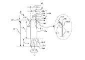
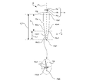
- the diameter of the neck portion is smaller than the diameter of the lower end portion of the lid body, and the diameter of the upper end portion of the main body peripheral wall portion and the outer shape of the end face of the cut surface of the shoulder portion in the longitudinal direction is a circular arc, and the tangent angle, which is the angle of the tangent line of the circular arc at the intermediate position of the circular arc in the longitudinal direction with respect to the orthogonal direction, is , an acute angle equal to or greater than a predetermined minimum angle and equal to or less than a predetermined maximum angle, wherein the minimum angle is 30 degrees and the maximum angle is 80 degrees.
- the diameter of the neck portion is smaller than the diameter of the lower end portion of the lid and the upper end portion of the peripheral wall of the main body
- the outer shape of the shoulder portion is an arc
- the middle portion in the longitudinal direction Since the tangential angle of the arc at the position is defined to be 30 degrees or more and 80 degrees or less with respect to the orthogonal direction, a larger gap is formed between the lid and the main body peripheral wall than when the angle is smaller than 30 degrees. occurs. Therefore, when the user grips the vicinity of the lower end of the lid with fingers and rotates the lid relative to the container body to remove the lid, the fingers of the user gripping the lid come into contact with the container body. or the contact area becomes relatively small. This means that the user's fingers are lessened by unnecessary friction that does not affect the removal of the lid. This allows the user to more effectively remove the lid from the main body.
- a predetermined portion of the neck in the longitudinal direction is not positioned inside the lid, It is configured to be exposed to the outside of the lid, and the extent to which the predetermined portion of the neck in the longitudinal direction is exposed to the outside of the lid is defined by a relationship with the diameter of the lower end of the lid. It is a container for fluids.
- the lower end of the lid in the state where the container body and the lid are engaged, the lower end of the lid is lower than in the case where the entire neck in the longitudinal direction is not exposed to the outside. and the upper end portion of the peripheral wall of the main body.
- the extent to which the neck portion is exposed is defined by the relationship with the diameter of the lower end portion of the lid.
- a ninth invention is the configuration of any one of the first invention to the eighth invention, wherein the internal shape of the end surface of the cut surface of the shoulder portion in the longitudinal direction is a circular arc, and the internal shape of the shoulder portion A tangent line of the arc at an intermediate position in the direction intersects with a tangent line in the longitudinal direction of the inner shape of the section of the main body peripheral wall portion where the main body peripheral wall portion connects with the shoulder portion at an obtuse angle, and the obtuse angle is 120 degrees. It is a container for fluid defined as an angle within a predetermined range defined from 160 degrees to 160 degrees.
- the direction of movement is greater than when the shoulder portion and the peripheral wall portion of the body are nearly perpendicular in the longitudinal direction. It won't change much. For this reason, the extent to which the force applied to the contents during flow fluctuates is relatively small. That is, the contents are extruded without a significant change in the direction and magnitude of the force applied by the user. This reduces the possibility of over-extrusion of the contents.
- liquid container of the present invention it is possible to provide a fluid container that reduces the possibility of excessive extrusion of the contents.
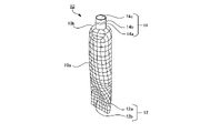
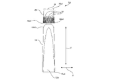
- FIG. 1 is a front view of a fluid container according to a first embodiment of the present invention
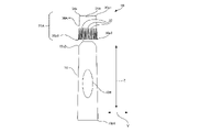
- FIG. FIG. 4 is a front view of the fluid container showing the inner member of the lid in a visible state
- FIG. 4 is a front view of a container body, and an enlarged schematic end view in the longitudinal direction near the boundary between a shoulder portion and a peripheral wall portion of the container
- It is a rear view of a container main body.
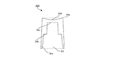
- It is a side view of a container main body.
- FIG. 4A is a side view of a container body with auxiliary lines for explanation, and a schematic enlarged view of a concave portion.
- FIG. It is the front view of a container main body, and a schematic end elevation of a orthogonal direction.
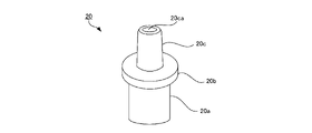
- FIG. 2 is a schematic perspective view of a distal tip;
- Fig. 3 is a schematic end view of the distal tip in the longitudinal direction;
- FIG. 4 is a front view of a state in which the distal tip is connected to the container body;
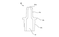
- Fig. 2 is a schematic perspective view of an outer cap;
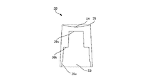
- Fig. 10 is a schematic end view of the outer cap in the longitudinal direction;
- Fig. 2 is a schematic perspective view of an inner cap;
- Fig. 2 is a schematic cross-sectional view of the inner cap in the longitudinal direction;
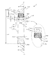
- FIG. 4 is a schematic cross-sectional view of a state in which the outer cap and the inner cap are connected;
- FIG. 17 is a schematic bottom view seen from below (in the direction of arrow X1 in FIG. 16) in a state where the outer cap and the inner cap are connected;
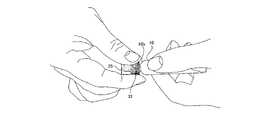
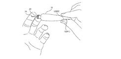
- FIG. 4 is a diagram showing an example of a state in which the fluid container is held with one hand; It is a figure which shows an example of the state which removes a cover body from a container main body. It is a figure which shows an example of the state which takes out the content from a container main body.
- FIG. 4 is a diagram showing forces acting when contents are taken out from a container body;
- FIG. 4 is a diagram showing forces acting when contents are taken out from a container body;
- FIG. 10 is a diagram showing deformation of the concave portion when the contents are taken out from the container body;
- FIG. 10 is a diagram showing a state in which contents are taken out when the contents of the container body become small.
- FIG. 10 is a diagram showing a state in which contents are taken out when the contents of the container body become small. It is a figure which shows an example of the conventional container. It is a figure which shows an example of the conventional container main body.
- FIG. 10 is a diagram showing an example of a state in which a lid is removed from a conventional container body; It is a figure which shows the state which takes out the content from the conventional container main body.
- FIG. 10 is a diagram showing forces acting when contents are taken out from a conventional container body.
- FIG. 10 is a diagram showing forces acting when contents are taken out from a conventional container body.
- FIG. 4 is a front view of a fluid container according to a second embodiment of the present invention
- Fig. 10 is a front view of a fluid container according to a third embodiment of the present invention
- Fig. 2 is a schematic perspective view of an outer cap
- Fig. 10 is a schematic end view of the outer cap in the longitudinal direction;
- the "longitudinal direction” means the longitudinal direction of the container 1 shown in FIG. 1 etc., ie, the direction shown by the arrow Z in FIG.
- a direction orthogonal to the longitudinal direction means a direction orthogonal to the longitudinal direction of the container 1, that is, the direction indicated by arrow V in FIG.
- “Upper” means the direction in which the upper end portion 30p1 of the lid 25 is positioned in the container 1 .
- Downward means the direction in which the lower end portion 10p4 of the container body 10 is positioned in the container 1.
- “Height direction” means the direction indicated by arrow T in the side view of FIG.
- Height means the distance in the height direction from the central axis Z1 in the side view of the container body 10 shown in FIG.
- Low height or “small height” means that the distance is short
- high height or “large height” means that the distance is long.
- the surfaces viewed from the two directions in which the projected area of the container 1 is the largest are defined as “principal surfaces”. That is, the front view of FIG. 3 and the rear view of FIG. 4 show the main surface of the container 1 .
- FIG. 1 An overall configuration of a container 1 according to a first embodiment of the present invention will be described with reference to FIGS. 1 to 8.
- FIG. The container 1 is a cylindrical container and is formed in an elongated shape as a whole.
- the container 1 is composed of a container body 10 and a lid 25 .
- the container body 10 and the lid 25 are detachably engaged.
- Contents are stored in the container body 10 .
- the contents are fluid.
- This fluid includes fluids of various viscosities, including low viscosity fluids such as pure water, and high viscosity fluids, such as gel and jelly.
- the contents are, for example, lotions, milky lotions, beauty essences, and creams such as beauty creams.
- the container 1 is an example of a fluid container.
- the container body 10 is an example of a container body, and the lid 25 is an example of a lid.
- the container 1 is a cosmetics container for storing cosmetics.
- the cosmetic product is, for example, a serum having a suitable viscosity.
- the container 1 is sized in its longitudinal direction so that it can be held with one hand of an average adult woman.
- the length L1 (see FIG. 2) of the container 1 is, for example, 95 millimeters (mm). Let us assume that the average female hand size is defined by hand length, hand width and girth, for example 170 millimeters, 75 millimeters and 180 millimeters respectively. However, unlike the present embodiment, the length L1 of the container 1 is not limited to 95 millimeters, and may be 80 millimeters or more and 110 millimeters or less, for example.
- a concave portion 12 is formed on one main surface of the container body 10 . Between the starting position 10p3 (see FIG. 2) and the lower end portion 10p4 (see FIG. 2), in the side view shown in FIGS. It is configured. Portions of the container body 10 other than the reverse curved peripheral wall portion 10aX are formed in an outwardly convex arc shape. As shown in FIG. 3, the concave portion 12 is formed as a recessed portion in the reverse curved peripheral wall portion 10aX. In the container body 10, the reverse curved peripheral wall portion 10aX is defined as a region closer to the lower end portion 10p4 than the shoulder portion 10b. The height of the recess 12 decreases from the side edges 12a toward the central portion 12b. Also, the height of the concave portion 12 decreases from the starting position 10p3 toward the lower end portion 10p4. In the front view shown in FIG. 3, the side edge portion 12a is formed in a substantially semi-elliptical shape and is open downward.
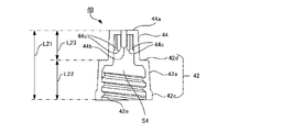
- the lid body 25 is configured in a substantially cylindrical shape whose diameter gradually increases from the upper end portion 30p1 to the lower end portion 30p2.
- the lid 25 is composed of an inner member 40 and an outer member 30 arranged outside the inner member 40 .
- FIG. 1 only the outer member 30 constituting the lid body 25 is shown, and the display of the inner member 40 is omitted.
- the outer member 30 is made of a light-transmissive material
- the inner member 40 is made of a light-impermeable material. Therefore, as shown in FIG. 2 , the inner member 40 can be visually recognized from the outside of the lid 25 through the outer member 30 .
- the outer member 30 is made of G-PET (Glycol-modified PET) in this embodiment, but the light-transmitting material is not limited to G-PET in the present invention.
- the inner member 40 is made of colored PP (polypropylene), but in the present invention, the light-impermeable material is not limited to colored PP.
- Outer member 30 and inner member 40 are formed, for example, by injection molding.
- the external shape of the outer member 30 is cylindrical with a slightly expanding diameter downward. Note that unlike the present embodiment, the external shape of the outer member 30 may be substantially cylindrical. An upper surface 34 of the outer member 30 is formed in a partially spherical shape that is convex downward.
- a plurality of filaments 32 are formed on the outer peripheral wall of the outer member 30 so as to extend from a substantially intermediate position in the longitudinal direction to the lower end portion 30p2.
- the filament 32 has a linear structure that protrudes outward, and serves as an anti-slip to prevent a finger from slipping when the user rotates the lid body 25 with respect to the container body 10. Function.
- the container body 10 is configured to be elastically deformed by an external force. That is, the container body 10 is deformed by an external force, but returns to its original shape when the force is removed.
- the container body 10 is pressed from the outside while the contents are stored in the container body 10, the container body 10 is deformed and the contents are discharged.
- gas usually air
- the shape of the container body 10 returns to its original shape, and at this time, gas (usually air) having the same volume as the volume of the discharged contents enters the container body 10. It's designed to go in. Thereby, the container body 10 can maintain its original shape regardless of the amount of contents stored inside.
- the container body 10 is formed by molding plastic resin.
- the plastic resin is polyethylene resin, more specifically, low-density polyethylene resin, and the molding method is blow molding, but in the present invention, the plastic resin and molding method are limited to these.
- the outer surface of the container main body 10 is subjected to matte processing, which suppresses the smoothness of the surface by providing fine irregularities as the surface processing.
- matte processing suppresses the smoothness of the surface by providing fine irregularities as the surface processing.
- this surface treatment is not visible to the user as the shape of the container body 1, it is used when the user grips the container body 10 and when the user takes out the contents from the container body 10.
- the surface of the user's finger is slightly deformed to fit into the fine irregularities, and is easily fixed at a desired position on the surface of the container body 10, thereby facilitating operation.
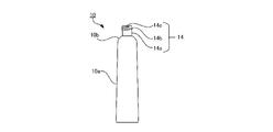
- the container body 10 includes a neck portion 14, a main body peripheral wall portion 10a (hereinafter referred to as a "peripheral wall portion 10a"), and a shoulder as a portion connecting the neck portion 14 and the peripheral wall portion 10a. It is composed of a portion 10b.
- the neck portion 14, the peripheral wall portion 10a and the shoulder portion 10b are integrally formed.
- positions in the longitudinal direction of the container body 10 are a connection portion 10p1 where the neck portion 14 and the shoulder portion 10b are connected, an upper end portion 10p2 where the shoulder portion 10b and the peripheral wall portion 10a are connected, and a lower end of the peripheral wall portion 10a.
- the end face of the cross section in the orthogonal direction is substantially circular at the neck 14, the shoulder 10b and the upper end 10p2 of the peripheral wall 10a.
- a region between the starting position 10p3 and the lower end portion 10p4 is a predetermined region in which the concave portion 12 is formed.
- the external shape and the internal space are similar.
- the wall thickness of the peripheral wall portion 10a is 1 millimeter (mm) and the wall thickness of the shoulder portion 10b is also 1 millimeter (mm).
- the thickness of the wall of the peripheral wall portion 10a and the thickness of the wall of the shoulder portion 10b are not limited to the above. Wall thickness may be increased.
- the neck 14 is configured such that both the diameter of the inner diameter and the diameter of the outer diameter are substantially constant over the longitudinal direction, that is, over the top and bottom. That is, the basic shape of the neck portion 14 is a cylindrical shape with a constant diameter.
- the neck portion 14 is configured to be engaged with the lid 25.
- a screw 14b is formed on the outer surface of the neck peripheral wall 14a, and the upper end portion 14c is an open opening.
- a peripheral wall portion 10a of the container body 10 is a closed portion with a closed lower end portion 10p4.
- the outer diameter d2 of the neck portion 14 (the neck peripheral wall 14a in FIG. 3) is smaller than the outer diameter d1 of the lower end portion 30p2 of the lid 25, and the upper end portion 10p2 of the peripheral wall portion 10a. It is formed smaller than the outer diameter d3.
- the diameter d1 of the lower end portion 30p2 of the lid body 25 is substantially the same as the diameter d3 of the upper end portion 10p2 of the peripheral wall portion 10a.
- the outer width w1 of the lower end portion 10p4 of the peripheral wall portion 10a is larger than the diameter d3.
- diameter d1 and diameter d3 are 14.4 millimeters
- diameter d2 is 8.0 millimeters
- width w1 is 19.2 millimeters.
- the diameter d1 of the lower end portion 30p2 of the lid 25 does not have to be substantially the same as the diameter d3 of the upper end portion 10p2 of the peripheral wall portion 10a. There may be a difference of about 10% based on the diameter of one of the two.
- the width of the container body 10 in a front view is maximized near the lower end portion 10p4.
- a tangent line Lc1 of the arc at an intermediate position in the longitudinal direction of the outer shape of the shoulder portion 10b has an angle ⁇ 1 with respect to the orthogonal direction.
- the angle ⁇ 1 is called tangent angle ⁇ 1.
- the tangent angle ⁇ 1 is defined as an acute angle that is equal to or greater than a predetermined minimum angle and equal to or less than a predetermined maximum angle.
- the minimum angle is 30 degrees and the maximum angle is 80 degrees. Desirably, the minimum angle is 40 degrees and the maximum angle is 70 degrees. In this embodiment, the tangent angle ⁇ 1 is 45 degrees.
- FIG. 3 also shows an enlarged schematic end view of the vicinity of the upper end portion 10p2 of the container body 10 in the longitudinal direction.
- the enlarged schematic end view of FIG. 3 is a view of the container body 10 cut vertically along its diameter.
- the outer shape and inner shape of the end face of the cut surface of the shoulder portion 10b in the longitudinal direction are circular arcs.
- the outer shape and inner shape of the end face of the cut surface of the shoulder portion 10b are similar circular arcs.
- a circular arc that is the inner shape of the end surface of the shoulder portion 10b will be described.
- a tangent line Lc2 of the circular arc at an intermediate position in the longitudinal direction of the inner shape of the shoulder portion 10b intersects at an angle ⁇ 2 with a longitudinal tangent line of the inner shape of the cross section near the upper end portion 10p2 of the peripheral wall portion 10a.
- the angle ⁇ 2 is called the tangent angle ⁇ 2.
- the tangential angle ⁇ 2 is an obtuse angle defined as an angle within a predetermined range of 120 degrees or more and 160 degrees or less.
- the tangential angle ⁇ 2 is desirably 130 degrees or more and 150 degrees or less. In this embodiment, the tangent angle ⁇ 2 is 135 degrees.
- the upper end portion 10p2 of the peripheral wall portion 10a and the inner surface of the shoulder portion 10b intersect at an angle larger than the tangential angle ⁇ 2, for example, 170 degrees or more and 180 degrees or less.
- the neck portion 14 is not completely positioned inside the lid body 25 when the container body 10 and the lid body 25 are engaged with each other. That is, a predetermined portion of the neck portion 14 in the longitudinal direction is not positioned inside the lid body 25 and is configured to be exposed to the outside.
- g1 is the length between the lower end 30p2 of the lid 25 and the upper end 10p2 of the peripheral wall 10a
- the connecting portion 10p1 is the length in the longitudinal direction.
- the length between the upper end portion 10p2 (that is, the length of the shoulder portion 10b in the longitudinal direction) is set to g3, and the exposed length of the neck portion 14 is set to g2.
- the length g2 of a predetermined portion of the neck portion 14 exposed to the outside of the lid 25 in the longitudinal direction is defined as a predetermined ratio in relation to the diameter d1 of the lower end portion of the lid 25 (see FIG. 2).
- a predetermined ratio of length g2 to diameter d1 (g2/d1) is defined in the range between 5% and 10%. In this embodiment, as described above, diameter d1 is 14.4 millimeters and length g2 is 1 millimeter.
- a space S1 having a length g1 is formed between the lower end portion 30p2 and the upper end portion 10p2 of the lid 25 by being exposed to the outside.
- length g1 is 5 millimeters. The inventors of the present invention found that if the tangential angle ⁇ 1 is too small, the space S1 of sufficient length and width is not created, and the lid 25 is sandwiched when the lid 25 is removed from the container body 10 as described later.
- the tangential angle .theta.1 is defined as a range in which such problems are unlikely to occur as a result of trial and error.
- the length g2 is defined as a length that, as a result of trial and error, can further reduce the possibility of such problems occurring. That is, by configuring the lengths g1 to g3 and the tangential angle ⁇ 1 as described above, it is possible to reduce the possibility that the fingers that turn the lid 25 will come into contact with the container body 10, and the lid 25 can be removed efficiently.
- a space S1 can be formed for this purpose.
- the end face of the cut surface of the container body 10 in the orthogonal direction is substantially circular at the neck 14, the shoulder 10b, and the upper end 10p2, which is the portion of the peripheral wall 10a that connects with the shoulder 10b.
- the end faces of the cross section of the container body 10 in the orthogonal direction are a schematic end view on the AA line, a schematic end view on the BB line, and a schematic end view on the CC line.
- DD line schematic end view, EE line schematic end view, FF line schematic end view, and GG line schematic end view it is formed in a circular or elliptical shape convex outward and approaches the lower end portion 10p4.
- the reverse curved peripheral wall portion 10aX and the concave portion 12 exist between the starting position 10p3 and the lower end portion 10p4, so the end face is not a simple elliptical shape.
- the concave portion 12 is formed in a predetermined area of the peripheral wall portion 10a.
- the predetermined region of the peripheral wall portion 10a in which the concave portion 12 is formed is a region on at least one of the two main surfaces of the peripheral wall portion 10a.
- the predetermined region where the concave portion 12 is formed is defined as a region closer to the lower end portion 10p4 than the shoulder portion 10b in the longitudinal direction of the peripheral wall portion 10a. In this embodiment, as shown in FIG.
- the concave portion 12 is formed in a region between the starting position 10p3 and the lower end portion 10p4.
- the area of the main surface including the concave portion 12 is configured as a reverse curved peripheral wall portion 10aX that is arcuately convex toward the inside of the container body 10 in a side view. That is, the reverse curved peripheral wall portion 10aX is formed in the region between the starting position 10p3 and the lower end portion 10p4, and the recessed portion 12 is the recessed portion of the reverse curved peripheral wall portion 10aX.
- the outer shape 10aL of the left side peripheral wall portion 10a and the outer shape 10aR of the right side peripheral wall portion 10a are not bilaterally symmetrical. If the outer shape 10aL is symmetrical with the outer shape 10aR, it becomes a virtual outer shape 10aS indicated by a dotted line. That is, the reverse curved peripheral wall portion 10aX causes a difference between the virtual outer shape 10aS and the outer shape 10aL.
- the container body 10 has a substantially bilaterally symmetrical shape, but as shown in FIG. , the container body 10 is configured to have a left-right asymmetrical shape with respect to the central axis Z1 in a side view. This asymmetrical shape is visible to the user, and thus attracts the user's attention.
- the height of the reverse curved peripheral wall portion 10aX is lower than the right peripheral wall portion 10aR at the corresponding position in the longitudinal direction.
- the height of the corresponding position of the concave portion 12 is lower than the height of the reverse curved peripheral wall portion 10aX, and is the lowest at the central portion 12b.
- the portions other than the recessed portion 12 are configured as convex portions whose end surfaces of cross-sectional surfaces in the orthogonal direction are outwardly convex.
- the portions other than the reverse curved peripheral wall portion 10aX are outwardly convex as can be understood from the schematic end view on line AA, the schematic end view on line BB, and the schematic end view on line CC, for example. It is formed in a curved shape.
- the reverse curved peripheral wall portion 10aX is formed, for example, as can be understood from the schematic end view on the DD line, the schematic end view on the EE line, the schematic end view on the FF line, and the schematic end view on the GG line in FIG.
- the main surface has an outwardly convex curved surface shape
- the other main surface has an inwardly convex curved surface shape.
- the distance between the inner surface of the central portion 12b of the concave portion 12 and the corresponding position of the inner surface of the lower main surface in the orthogonal direction is the distance h1 in the CC line schematic end view and the DD line schematic end view.
- the distance is h2
- the distance is h3 in the EE line schematic end view
- the distance is h4 in the FF line schematic end view
- the distance is h5 in the GG line schematic end view.
- the distances between these inner surfaces are in the relation of the formula: "h1>h2>h3>h4>h5".
- the distance between the inner surfaces is also a size that allows the container body 10 to deform when a force directed from the outside to the inside is applied to the two main surfaces of the container body 10 corresponding to each other in the longitudinal direction.
- the distance between the inner surfaces becomes shorter as the lower end portion 10p4 is approached. This means that the container body 10 has less room to deform in the height direction as it approaches the lower end portion 10p4.
- the formation of the concave portion 12 reduces the room for deformation in the height direction as the lower end portion 10p4 is approached.
- this configuration of the recessed portion 12 facilitates proper discharge when the container body 10 is relatively overfilled, and also allows the stored contents of the container body 10 to be displaced relative to each other. It makes it possible to facilitate the discharge of an appropriate amount even when the amount is relatively small.
- the difference between the virtual outline 10aS and the portion where the height of the central portion 12b of the concave portion 12 is the most different, that is, the maximum depth md1 of the concave portion 12 is defined between 0.7 mm and 3.5 mm, Desirably, it is defined between 1.0 millimeters and 3.0 millimeters, and in this embodiment is 1.8 millimeters.
- the size of the concave portion 12 in the longitudinal direction and in the orthogonal direction is defined as a size that can be contacted by the user's finger.
- the maximum width w12 (see FIG. 2) of the recessed portion 12 is set to be equal to or more than half the width w1 of the lower end portion 10p4 and equal to or less than the width w1 of the lower end portion 10p4.
- the maximum width w12 is smaller than the width w1 of the lower end portion 10p4 by the thickness of the peripheral wall portion 10a. That is, the maximum width w12 of the recessed portion 12 is limited by the thickness of the peripheral wall portion 10a, but is configured as the maximum possible width in terms of the structure of the container body 10. As shown in FIG.
- the maximum width of the concave portion 12 may be defined as a width that is two-thirds or more of the width w1 of the lower end portion 10p4 and less than or equal to the width w1.
- the longitudinal dimension of the concave portion 12, that is, the distance L3 (see FIG. 6) between the starting position 10p3 and the lower end portion 10p4 is, for example, 18 millimeters, as will be described later.
- the recessed portion 12 is formed so that, in plan view, the width of the main surface of the recessed portion 12 increases from a position corresponding to the starting position 10p3 of the recessed portion 12 in the longitudinal direction toward the lower end portion 10p4.
- the concave portion 12 is formed in a substantially semi-elliptical shape in plan view on the main surface, and in the longitudinal direction, the upper portion corresponding to the start position 10p3 is closed and the lower portion is open.
- the length L2 of the peripheral wall portion 10a in the longitudinal direction is the length L3 of the area where the concave portion 12 is formed, and the length L4 of the portion where the concave portion 12 is not formed.
- the length L3 is smaller than the length L4 in this embodiment.
- length L3 is 18 millimeters and length L4 is 52 millimeters.
- the maximum width of the concave portion 12 is the width at the lower end portion 10p4, which is, for example, 17 millimeters.
- the length, width, and depth md1 of the concave portion 12 are designed to minimize the degree of reduction in the volume of the container body 10 while preventing excessive discharge of the contents by the concave portion 12. This range was found as a result of trial and error.
- the tip 20 has a base portion 20a, an enlarged diameter portion 20b and a tip portion 20c. As shown in FIG. 10, the distal tip 20 is formed in a hollow structure with upper and lower openings, and has a space S2.
- the distal tip 20 is connected to the container body 10.
- the container body 10 When the container body 10 is pressed from the outside while the contents are stored in the container body 10, the contents pass through the space S2 of the tip 20 and are discharged from the open end 20ca of the tip 20c. .
- the outer member 30 is formed in a columnar shape whose diameter increases from the top to the bottom, and the inner side is a space S3 that is open at the bottom. As described above, the outer member 30 is made of a material having optical transparency.
- An upper surface 34 of the outer member 30 is formed in a partially spherical shape that is convex downward.
- An annular flat portion 35 having a flat upper surface is formed around the upper surface 34 .
- the upper surface 34 and the annular flat portion 35 are used as the upper surface portion of the outer member 30, and the upper surface 34, which is a part of the upper surface portion, has a partially spherical shape convex downward. good.
- the filaments 32 are formed over the length L12.
- the filaments 32 are not formed in the length L13 portion above the outer member 30 in the longitudinal direction.
- inner member 40 has a base portion 42 and a tip portion 44 .
- the outer shape of the base portion 42 and the tip portion 44 is substantially cylindrical, and the diameter becomes slightly smaller toward the top.
- the maximum diameter of the outer shape of the tip portion 44 is smaller than the minimum diameter of the outer shape of the base portion 42 (hereinafter referred to as "diameter condition").
- L22 is longer than L23.
- L22 is substantially the same length as, or slightly shorter than, length L12 (see FIG. 2) of filaments 32 of outer member 30 .
- the inner side of the inner member 40 forms a space S4 with an open bottom.
- a screw 42e is formed inside the base 42.
- the screw 42e engages with the screw 14b (see FIG. 3, etc.) of the neck portion 14 of the container body 10 when the container body 10 and the lid body 25 are engaged with each other.
- a center projection 44 b is formed at the center of the inner ceiling surface of the tip portion 44 .
- the center protrusion 44b is inserted from the open end 20ca of the tip 20 (see FIG. 9) into the tip 20c to seal the open end 20ca when the container body 10 and the lid 25 are engaged with each other.
- a plurality of ridges 44 c are formed on the inner peripheral wall of the tip portion 44 .
- the projection 44c guides and positions the front end 20c of the front tip 20 (see FIG. 9) when the container body 10 and the lid 25 are engaged, and ensures that the center projection 44b moves from the open end 20ca to the front end. It is inserted into portion 20c and assists in sealing open end 20ca.
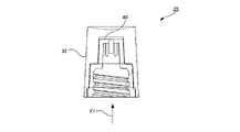
- the outer member 30 is arranged outside the inner member 40 to form the lid body 25 .
- the cover 25 of FIG. 16 is viewed from below indicated by an arrow X1
- the view shown in FIG. 17 is obtained.
- the shoulder portion 42d (see FIG. 15) of the inner member 40 contacts the intermediate ceiling surface 36b (see FIG. 13) of the outer member 30, and the enlarged diameter portion 42c (see FIG. 15) of the inner member 40 abuts on the bottom enlarged diameter portion 36a (see FIG. 13).
- a protruding portion 42b see FIG.
- the filars 32 of the outer member 30 are positioned outside the peripheral wall of the base 42 of the inner member 40 and at the distal end 44 . It is substantially not arranged outside the peripheral wall.
- the striations 32 are relatively visible to the user because the inner member 40 is made of a non-light-transmitting material compared to when the inner member 40 is made of a light-transmitting material. is easily configured. Furthermore, since the distance between the filament 32 and the peripheral wall of the base 42 is smaller by satisfying the diameter condition than when the diameter condition is not met, the filament 32 is relatively visually recognized by the user. has become easier.
- the tip portion 44 of the inner member 40 can be relatively clearly seen through the outer member 30. . Furthermore, by satisfying the diameter condition, the distance between the portion of the outer member 30 where the filaments 32 are not formed and the outer circumference of the tip portion 44 is greater than when the diameter condition is not satisfied. Through the portion of 30 where the filament 32 is not formed, the distal end portion 44 is configured to be more clearly visible from the outside.
- the filament 32 of the outer member 30 and the tip portion 44 of the inner member 40 are easily visible from the outside.
- the reverse curved peripheral wall portion 10aX functions as a structure for guiding the user's consciousness to the recessed portion 12 more reliably and bringing the finger into contact with the recessed portion 12 more reliably.
- the user is less likely to drop the container 1, and the user's mental state can be prevented from becoming unstable.
- the upper surface 34 is configured in a partially spherical shape and the concave portion 12 is formed, so that the container 1 can be gripped so as to be pinched.
- the lid 25 When removing the lid 25 from the container body 10, for example, as shown in FIG. 32 is gripped with two fingers and rotated. At this time, since the space S1 (see FIG. 2) exists between the main body peripheral wall portion 10a and the lid 25, the fingers of the right hand touch only the ridges 32 and do not touch the main body peripheral wall portion 10a. As a result, it is possible to avoid the friction caused by the fingers of the right hand coming into contact with the main body peripheral wall portion 10a. That is, the space S1 functions as friction avoidance means for avoiding unnecessary friction. As described above, the user of the container 1 can effectively grasp the container 1 and remove the lid 25 from the container body 10 before taking out the contents from the container body 10 . As a result, negative emotions such as anger and impatience do not occur, and a stable mental state can be maintained. This completes the preparation for carrying out a delicate finger operation when taking out the contents from the container main body 10 .
- the lid 25 removed from the container body 10 can be placed on a flat placement place such as a desk (not shown) with the upper surface 34 facing downward, for example.
- a flat placement place such as a desk (not shown) with the upper surface 34 facing downward, for example.
- the annular flat portion 35 comes into contact with the placement location, and the lid body 25 is placed stably.
- the container body 10 and the lid body 25 can be engaged with each other after the container body 10 is used. After that, it is sufficient to remove dirt from only the annular flat portion 35 of the lid body 25 .
- FIG. 21 and 22 are side views of the container body 10, the reverse curved peripheral wall portion 10aX is visible, and the concave portion 12 is not visible.
- the reference numerals of the concave portions 12 are also shown. This also applies to FIGS. 24 and 25.
- FIG. 21 and 22 are side views of the container body 10, the reverse curved peripheral wall portion 10aX is visible, and the concave portion 12 is not visible.
- the reference numerals of the concave portions 12 are also shown. This also applies to FIGS. 24 and 25.
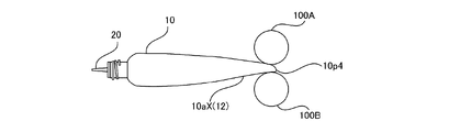
- the container main body 10 stores a relatively large amount of contents. For example, it is 70% or more of the volume of the container body 10 .
- This state is called a "filled state".
- reference numerals 100A and 100B represent fingers of the user.
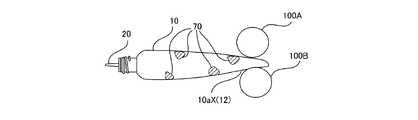
- a force is applied so as to sandwich the container body 10 between the fingers 100A and 100B.
- the force represented by the vector v1 acts on the content 70, and the content 70 is ejected from the tip 20.
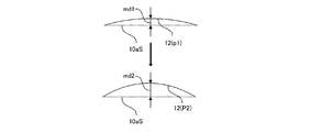
- the extent to which the force applied to the flowing contents 70 varies is relatively small. That is, the contents are ejected without a significant change in the direction and magnitude of the force applied by the user. This reduces the possibility that the content 70 will be excessively ejected from the distal tip 20 . Further, at this time, as shown in FIG. 23, the depth md1 of the concave portion 12 (degree of concave with respect to the imaginary outer shape 10aS) increases to a depth md2.
- the concave portion 12 is deformed, the direction of the concave shape does not change, and the depth only increases from md1 to md2. That is, the concave portion 12 does not undergo a sudden and large shape change. This further reduces the possibility that the content 70 is excessively discharged from the tip 20 .
- the container body 10 has less room for deformation in the height direction at a position closer to the lower end portion 10p4 due to the concave portion 12 being formed. .
- the portion near the lower end portion 10p4 of the concave portion 12 there is a possibility that the content 70 will be expelled excessively from the distal tip 20 compared to pressing other portions of the container body 10. is reduced. This is because the portion near the lower end portion 10p4 is configured as a portion of the container body 10 that has the least room for deformation even if the force from the outside is excessive.
- the container body 10 When the amount of the contents 70 stored in the container main body 10 decreases, pressing the portion near the lower end 10p4 discharges a smaller amount of the contents 70 than the appropriate amount. to press the upper part. Even in this case, the container body 10 has less room for deformation in the height direction due to the formation of the concave portion 12, compared to the case where the concave portion 12 is not present. The possibility that the contents 70 are excessively ejected from the distal tip 20 is reduced.
- the above-mentioned effect becomes more remarkable by forming the concave portion 12 on the reverse curved peripheral wall portion 10aX.
- a concave portion having the same room for deformation in the height direction as in the present embodiment (hereinafter referred to as a “temporary concave portion”) is formed. Then, at the end face of the cut surface in the orthogonal direction, the height difference between the side edge portion and the central portion of the temporary concave portion 12 is greater than the height difference between the side edge portion 12a and the central portion 12b of the concave portion 12 of the present embodiment. The difference in height becomes large.
- the rough end face shape of the pad side of the finger is an arc shape corresponding to the long axis of an ellipse, and the height H is greater than the width W. is low.
- the ratio of maximum height to maximum width (H/W) is larger than that of the concave portion 12.
- the recessed portion 12 is formed in the reverse curved peripheral wall portion 10aX, even if the ratio of maximum height to maximum width (H/W) is smaller than that of the provisional recessed portion, the height It is possible to reduce the room for deformation in the vertical direction. It should be noted that the above is an explanation of the advantageous effects of this embodiment, and does not exclude the provisional concave portion from the present invention.
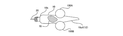
- the 24 and 25 show a case where the content 70 stored in the container 1 is small.
- the case where the content 70 becomes small is, for example, the case where the amount of the content 70 becomes 30% or less of the volume of the container body 10 .
- This state is called a "small amount state".
- the small amount state especially when the contents 70 are gel-like, the contents 70 are not concentrated in one place in the container main body 10, but are dispersed in a plurality of positions as shown in FIG. likely to be. Therefore, it is necessary to collect the dispersed contents 70 and then push them out. Also in this case, when taking out the contents 70 from the container main body 10, first, as shown in FIG. , and the concave portion 12 in the longitudinal direction.
- a force is applied so that the container body 10 is sandwiched between the fingers 100A and 100B, and the fingers 100A and 100B are moved while sliding toward the shoulder portion 10b. That is, in the container body 10, a force is applied to gather the dispersed contents 70 and guide them in the direction of the shoulder portion 10b. At this time, it is difficult to apply only the force directed toward the shoulder portion 10b to the contents 70, and the force directed in the opposite direction is also applied.
- the container body 10 is formed in a shape that flattens toward the bottom, the reverse curved peripheral wall portion 10aX is formed, and the concave portion 12 is formed in the reverse curved peripheral wall portion 10aX.
- the resistance of the contents 70 towards the bottom is greater than towards the shoulder 10b. Therefore, it is difficult for the contents 70 to face toward the bottom of the container body 10 .
- the formation of the concave portion 12 in the container body 10 reduces the possibility that the content 70 is excessively discharged from the tip 20 .
- the force that presses the container body 10 is greater than in the full state. Therefore, the closer the position is to the lower end portion 10p4, the smaller the room for deformation in the height direction. Therefore, even if a relatively large force is applied in the initial stage of force application, there is little room for the container body 10 to change in the height direction. less likely to be ejected.
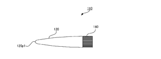
- FIG. 1 An example of a conventional container 110 will be described with reference to FIGS. 26 to 32.
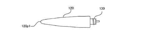
- the container 110 is composed of a main body 120 and a lid 140.
- the main body 120 is configured in a shape convex outward along the entire longitudinal direction, and the cross section of the portion connected to the lid body 140 is substantially circular, and the degree of flatness increases toward the end portion 120p1. Become.
- a distal tip 130 is connected to the main body 120 .
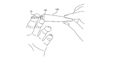
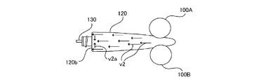
- reference numerals 100A and 100B represent fingers of the user.
- the fingers 100A and 100B are pressed so as to sandwich the container body 120.
- a force represented by vector v2 acts on contents 70, and furthermore, the contents 70 come into contact with the inner side of shoulder 120b and change direction significantly as represented by vector v2a.
- the extent to which the force applied to the contents during flow fluctuates is relatively large. This increases the possibility that the contents will be expelled excessively from the distal tip 130 . Further, at this time, as shown in FIG.
- the outwardly projecting shape of the container body 120 is deformed into an inwardly projecting shape. That is, the convex depth (degree of convexity with respect to the plane) k1 is the depth -k2. In this way, the rapid and large deformation of the container body 120 increases the possibility that the contents will be excessively discharged.
- ⁇ Second embodiment> A second embodiment will be described with reference to FIG. The description of matters common to the first embodiment is omitted.
- a concave portion 12A is formed over substantially the entire longitudinal direction of the container body 10. As shown in FIG.
- the concave portion 12A of the container 1A has a larger area than the concave portion 12 of the container 1 of the first embodiment, the volume of the container 1A is smaller than the volume of the container 1 if other conditions are the same. However, in the container 1A, even when the remaining amount of the contents is low, by pressing the concave portion 12A, the contents can be used completely while preventing excessive discharge of the contents. be able to.
- a third embodiment will be described with reference to FIG. The description of matters common to the first embodiment is omitted.
- the main surface of the container body 10 is formed with a concave portion 12B having an elliptical shape in plan view.
- the upper surface 34A of the outer member 30A of the lid 25A continues to the end, and the end forms an annular end 34a. That is, unlike the first embodiment, the annular flat portion 35 does not exist.
- the entire upper surface portion is an upper surface 34A having a partially spherical surface convex downward.
- the lid 25A removed from the container body 10 can be placed on a flat place such as a desk (not shown) with the top surface 34A facing downward. As a result, the annular end portion 34a abuts on the placement location, and the lid body 25 is placed stably.
- the container body 10 can be engaged with the lid 25A after the container body 10 is used. After that, the dirt can be removed only from the annular end portion 34a of the lid 25A.
- the fluid container of the present invention is not limited to the above embodiment, and various modifications can be made without departing from the gist of the present invention. Moreover, each of the above-described embodiments can be appropriately combined as long as there is no technical contradiction.
- the concave portions 12, 12A and 12B may be formed not only on one principal surface but also on both principal surfaces.
Landscapes
- Engineering & Computer Science (AREA)
- Mechanical Engineering (AREA)
- Closures For Containers (AREA)
Abstract
L'objectif de la présente invention est de fournir un contenant de fluide qui réduit la possibilité que le contenu soit pressé hors de celui-ci. Dans ce contenant de fluide 1, définissant les surfaces primaires en tant que surfaces dans les deux directions de la paroi périphérique de corps principal 10a où la surface de projection est maximale, un évidement 12, qui est une forme incurvée convexe vers l'intérieur, est formé sur au moins une surface des surfaces primaires, et l'évidement 12 est formé de telle sorte que la largeur de la surface primaire augmente vers le bas dans la direction longitudinale.
Priority Applications (1)
| Application Number | Priority Date | Filing Date | Title |
|---|---|---|---|
| PCT/JP2021/023488 WO2022269727A1 (fr) | 2021-06-21 | 2021-06-21 | Contenant de fluide |
Applications Claiming Priority (1)
| Application Number | Priority Date | Filing Date | Title |
|---|---|---|---|
| PCT/JP2021/023488 WO2022269727A1 (fr) | 2021-06-21 | 2021-06-21 | Contenant de fluide |
Publications (1)
| Publication Number | Publication Date |
|---|---|
| WO2022269727A1 true WO2022269727A1 (fr) | 2022-12-29 |
Family
ID=84545270
Family Applications (1)
| Application Number | Title | Priority Date | Filing Date |
|---|---|---|---|
| PCT/JP2021/023488 Ceased WO2022269727A1 (fr) | 2021-06-21 | 2021-06-21 | Contenant de fluide |
Country Status (1)
| Country | Link |
|---|---|
| WO (1) | WO2022269727A1 (fr) |
Citations (8)
| Publication number | Priority date | Publication date | Assignee | Title |
|---|---|---|---|---|
| JPS59118749U (ja) * | 1983-02-01 | 1984-08-10 | 吉田工業株式会社 | 合成樹脂製チユ−ブ容器 |
| JPS642750U (fr) * | 1987-06-22 | 1989-01-10 | ||
| JPH0642628U (ja) * | 1992-11-10 | 1994-06-07 | 喜重郎 山本 | 流動体用容器 |
| JP2001315809A (ja) * | 2000-05-02 | 2001-11-13 | Yoshida Industry Co Ltd | アルミ・ラミネートチューブ容器 |
| JP2008062973A (ja) * | 2006-09-07 | 2008-03-21 | Sakura Color Prod Corp | チューブ容器 |
| JP3185149U (ja) * | 2013-05-22 | 2013-08-01 | 和彦 中村 | チューブ容器 |
| JP2016101709A (ja) * | 2014-11-28 | 2016-06-02 | 株式会社吉野工業所 | チューブ容器の製造方法およびチューブ容器 |
| JP2018034877A (ja) * | 2016-09-02 | 2018-03-08 | セイコーエプソン株式会社 | ボトルセット、ボトル |
-
2021
- 2021-06-21 WO PCT/JP2021/023488 patent/WO2022269727A1/fr not_active Ceased
Patent Citations (8)
| Publication number | Priority date | Publication date | Assignee | Title |
|---|---|---|---|---|
| JPS59118749U (ja) * | 1983-02-01 | 1984-08-10 | 吉田工業株式会社 | 合成樹脂製チユ−ブ容器 |
| JPS642750U (fr) * | 1987-06-22 | 1989-01-10 | ||
| JPH0642628U (ja) * | 1992-11-10 | 1994-06-07 | 喜重郎 山本 | 流動体用容器 |
| JP2001315809A (ja) * | 2000-05-02 | 2001-11-13 | Yoshida Industry Co Ltd | アルミ・ラミネートチューブ容器 |
| JP2008062973A (ja) * | 2006-09-07 | 2008-03-21 | Sakura Color Prod Corp | チューブ容器 |
| JP3185149U (ja) * | 2013-05-22 | 2013-08-01 | 和彦 中村 | チューブ容器 |
| JP2016101709A (ja) * | 2014-11-28 | 2016-06-02 | 株式会社吉野工業所 | チューブ容器の製造方法およびチューブ容器 |
| JP2018034877A (ja) * | 2016-09-02 | 2018-03-08 | セイコーエプソン株式会社 | ボトルセット、ボトル |
Similar Documents
| Publication | Publication Date | Title |
|---|---|---|
| US20130153532A1 (en) | Plastic container having enhanced crush resistance and pouring stability | |
| EP3251960B1 (fr) | Récipient à double paroi | |
| EP3632811B1 (fr) | Récipient en résine synthétique | |
| JP5640355B2 (ja) | 注出口栓及び包装容器 | |
| WO2022269727A1 (fr) | Contenant de fluide | |
| JP2005088973A (ja) | 容器 | |
| JP7394687B2 (ja) | 薄肉容器 | |
| JP2007308195A (ja) | 可撓性容器 | |
| US9815610B2 (en) | Squeeze container | |
| JP2004250063A (ja) | 容器 | |
| JP2021054447A (ja) | 積層剥離容器 | |
| JP2007091341A (ja) | 可撓性容器 | |
| JP2005153901A (ja) | 注出容器 | |
| JP7730010B2 (ja) | 二重容器 | |
| JP7453520B2 (ja) | プラスチック容器 | |
| CN221600645U (zh) | 防划伤开塞露瓶 | |
| JP7154042B2 (ja) | スクイズボトル | |
| JP2018115007A (ja) | プラスチックキャップ | |
| JP2023088573A (ja) | 二重容器 | |
| JP2022026891A (ja) | スクイズボトルおよび二重容器 | |
| JP6709703B2 (ja) | ボトル型容器 | |
| JP2024077974A (ja) | スクイズボトルおよび二重容器 | |
| CN221243451U (zh) | 组装式开塞露瓶 | |
| WO2025063289A1 (fr) | Contenant de type de bouteille souple | |
| JP3242638U (ja) | 回転部材 |
Legal Events
| Date | Code | Title | Description |
|---|---|---|---|
| 121 | Ep: the epo has been informed by wipo that ep was designated in this application |
Ref document number: 21947016 Country of ref document: EP Kind code of ref document: A1 |
|
| NENP | Non-entry into the national phase |
Ref country code: DE |
|
| 122 | Ep: pct application non-entry in european phase |
Ref document number: 21947016 Country of ref document: EP Kind code of ref document: A1 |
|
| NENP | Non-entry into the national phase |
Ref country code: JP |