WO2024252621A1 - Procédé d'inspection pour pipeline enterré souterrain - Google Patents
Procédé d'inspection pour pipeline enterré souterrain Download PDFInfo
- Publication number
- WO2024252621A1 WO2024252621A1 PCT/JP2023/021363 JP2023021363W WO2024252621A1 WO 2024252621 A1 WO2024252621 A1 WO 2024252621A1 JP 2023021363 W JP2023021363 W JP 2023021363W WO 2024252621 A1 WO2024252621 A1 WO 2024252621A1
- Authority
- WO
- WIPO (PCT)
- Prior art keywords
- pipeline
- database
- propagation
- waves
- camera
- Prior art date
- Legal status (The legal status is an assumption and is not a legal conclusion. Google has not performed a legal analysis and makes no representation as to the accuracy of the status listed.)
- Ceased
Links
Images


Classifications
-
- E—FIXED CONSTRUCTIONS
- E03—WATER SUPPLY; SEWERAGE
- E03F—SEWERS; CESSPOOLS
- E03F7/00—Other installations or implements for operating sewer systems, e.g. for preventing or indicating stoppage; Emptying cesspools
-
- G—PHYSICS
- G01—MEASURING; TESTING
- G01N—INVESTIGATING OR ANALYSING MATERIALS BY DETERMINING THEIR CHEMICAL OR PHYSICAL PROPERTIES
- G01N22/00—Investigating or analysing materials by the use of microwaves or radio waves, i.e. electromagnetic waves with a wavelength of one millimetre or more
Definitions
- This disclosure relates to technology for estimating conditions inside pipelines buried underground.
- Fiber optic cables are installed on utility poles or in conduits, and are provided from station buildings to individual homes, etc.
- Non-Patent Document 1 Previously, pipe cameras were used to check for abnormalities in pipes to check the state of continuity (see, for example, Non-Patent Document 1).
- Visual continuity inspections using cameras can visually check for the presence of obstacles in the pipeline, but there is a problem in that it is difficult to determine what type of obstacle is present just by looking. In particular, because the water that has entered the pipeline is mixed with soil and sand, there is a problem in that it is difficult to determine the presence of rust inside the pipeline.
- the purpose of this disclosure is to make it possible to estimate the conditions inside a pipeline.
- Obstacles in pipelines can be soil, water, or rust.
- the behavior of radio waves, sound waves, light, etc. in pipelines where such obstacles exist varies and can be measured in advance. Therefore, this disclosure makes it possible to estimate the condition inside the pipeline based on at least one of the propagation characteristics and reflection characteristics inside the pipeline.
- the system disclosed herein includes a database that stores at least one of the propagation characteristics and reflection characteristics within a pipeline for each type of obstacle present within the pipeline, and a computing device that estimates the condition within the pipeline based on the database, and executes the method disclosed herein.
- the system of the present disclosure may include a measuring device that measures the propagation characteristics or reflection characteristics within the pipeline.
- the computing device may estimate the condition within the pipeline by comparing the measurement results from the measuring device with the database.
- the database may store the propagation or reflection characteristics of at least one of radio waves, sound waves, or light waves.
- the database may store the propagation or reflection characteristics of a plurality of different frequencies.
- the types of obstacles may include at least one of soil, water, and rust.
- the system disclosed herein includes a transmitting device that transmits radio waves, and the measuring device receives the radio waves transmitted from the transmitting device.
- the transmitting device may transmit multiple radio waves with different frequencies.
- the measuring device may receive multiple radio waves with different frequencies.
- the system disclosed herein includes a transmitting device that transmits sound waves, and the measuring device receives the sound waves transmitted from the transmitting device.
- the transmitting device may transmit multiple sound waves with different frequencies.
- the measuring device may receive multiple sound waves with different frequencies.
- the system disclosed herein includes a transmitting device that transmits light waves, and the measuring device receives the light waves transmitted from the transmitting device.
- the transmitting device may transmit multiple light waves with different frequencies.
- the measuring device may receive multiple light waves with different frequencies.
- the system disclosed herein may include a camera capable of capturing images of the inside of the pipeline, and a display device that displays the images captured by the camera and the estimation results of the computing device.
- the system disclosed herein may include a transmitting device that transmits at least one of radio waves, sound waves, and light waves, and the transmitting device may be mounted on the camera.
- This disclosure makes it possible to estimate the conditions inside a pipeline.
- 1 is an example embodiment of a system of the present disclosure. An example of a method for estimating the state inside a pipeline will be described. An example of information stored in the database is shown below. 1 is an example embodiment of a system of the present disclosure. 1 is an example embodiment of a system of the present disclosure.
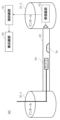
- FIG. 1 shows an example of a system configuration of this embodiment.
- the system of this embodiment includes a transmitting device 91, a receiving device 92, a computing device 93, and a display device 95.
- the transmitting device 91 is a device that transmits radio waves continuously or periodically.
- the receiving device 92 is a device that receives radio waves and functions as the "measuring instrument" of this disclosure.
- the computing device 93 is a device that estimates the state inside the pipeline 82 based on the reception result of the receiving device 92.
- the display device 95 is a device that displays the determination result of the determination device 93.
- the display device 95 may be provided in the determination device 93.
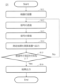
- FIG. 2 shows an example of a method for estimating the state inside a pipeline.
- S11 A transmitting device 91 and a receiving device 92 are installed in manholes 81-1 and 81-2 located at both ends of a pipeline 82.
- S12 The transmitter 91 transmits radio waves toward the pipeline 82.
- S13 The receiving device 92 receives the radio waves from the pipeline 82. As a result, the receiving device 92 receives the radio waves that have passed through the pipeline 82.
- S14 The receiving device 92 outputs the reception result to the calculation device 93.
- the reception result of the receiving device 92 is, for example, the reception strength of the radio wave.
- the radio waves transmitted and received in steps S12 and S13 are, for example, radio signals of different frequency bands.
- the transmitting device 91 transmits radio signals of frequency bands of 5 GHz, 30 GHz, and 60 GHz, which have different degrees of attenuation in water.
- the frequency band of the radio waves may be selected according to the diameter of the pipe 82; for example, the larger the diameter, the lower the frequency band that is used.
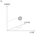
- the propagation attenuation of radio waves according to the type and amount of obstacles 70, such as dirt, water, and rust, present in the pipeline 82 is measured in advance and stored in a database provided in the computing device 93.
- a database provided in the computing device 93.
- four patterns of measurement results are stored in advance for each frequency: received power when the obstacle 70 is dirt and corrosion (rust), received power when the obstacle 70 is corrosion (rust) and water, received power when the obstacle 70 is dirt and water, and received power when the obstacle 70 is dirt, corrosion (rust) and water.
- the computing device 93 refers to the database, combines the measurement results of steps S11 to S14, and estimates the type of obstacle 70 that may be present in the pipeline 82, such as dirt, water, and rust. As a result, the type of obstacle 70 that may be present in the pipeline 82 is displayed on the display device 95.
- the calculation device 93 may estimate the amount of obstacles 70 in addition to the type of obstacles 70.
- the calculation device 93 may also estimate the percentage of the cavity in the pipeline 82 that is occupied by obstacles 70. Furthermore, for each type or combination of obstacles 70, it may be defined that a certain percentage or more of the obstacles 70 present in the pipeline 82 must exist to cause non-conduction. The calculation device 93 may then calculate the percentage probability of non-conduction based on the signal reception strength.
- the computing device 93 may determine the pipeline 82 with the highest conductivity possibility based on the reception strength and the amount of each obstacle 70. For example, when there is an equal amount of soil, water, and rust, the pipeline 82 with water may be selected as the pipeline with the highest conductivity possibility.
- steps S12 to S14 may be repeated from the installation of the transmitting device 91 and the receiving device 92 (S11).
- a signal other than radio waves such as sound waves or light
- the position of the transmitting device 91 and the receiving device 92 may be swapped and measurements may be performed again.
- the reflection characteristics reflected within the pipeline 82 may be measured.
- the system of this embodiment can classify and determine the quantity of obstacles in the pipeline 82 from a combination of the strengths of the received signals of multiple signals acquired using the receiving device 92, without using a pipe camera. Therefore, the system of this embodiment can easily perform continuity inspections and inspections of the condition inside the pipeline.
- the system of the present disclosure may include a blower and an anemometer.
- the blower is used to send air into the duct 82 from the transmitting device 91 side
- the anemometer is used to measure wind force on the receiving device 92 side, and the measurement result is output to the computing device 93. This can improve the estimation accuracy in the computing device 93.
- the system of the present disclosure may also include a blower, an anemometer, and a thermometer.
- the blower is used to send hot air from the transmitting device 91 into the duct 82
- the thermometer is used to measure the temperature on the receiving device 92 side
- the anemometer is used to measure the wind force, and these measurement results are output to the computing device 93. This can improve the estimation accuracy in the computing device 93.
- the system of this embodiment includes a pipe camera 94 in addition to the configuration of the first embodiment.
- An image captured by the pipe camera 94 is transmitted to a calculation device 93 and displayed on a display device 95.
- the system of this embodiment allows the image of the inside of the pipeline 82 captured by the pipe camera 94 to be viewed on the display device 95.
- Inspection of the pipeline 82 using the pipe camera 94 is performed, for example, before steps S11 to S14 in the first embodiment. At this time, if the type of obstacle 70 cannot be determined, the type of obstacle 70 can be estimated by performing steps S11 to S14 in the first embodiment.
- (Fourth embodiment) 5 shows an example of the system configuration of this embodiment.
- the transmitter 91 of the first embodiment is mounted on the tip of a pipe camera 94.
- the accuracy of classifying and measuring the quantity of obstacles 70 in the pipeline 82 can be improved by combining the images from the pipe camera 94 and the reception results of multiple signals acquired using the receiving device 92.
- the arithmetic device 93 of the present invention can also be realized by a computer and a program, and the program can be recorded on a recording medium or provided via a network.
- the program of the present disclosure is a program for causing a computer to realize each function of the arithmetic device 93 according to the present disclosure, and is a program for causing a computer to execute each procedure of the method executed by the arithmetic device 93 according to the present disclosure.
Landscapes
- Life Sciences & Earth Sciences (AREA)
- Physics & Mathematics (AREA)
- Health & Medical Sciences (AREA)
- General Physics & Mathematics (AREA)
- Chemical & Material Sciences (AREA)
- Analytical Chemistry (AREA)
- Biochemistry (AREA)
- General Health & Medical Sciences (AREA)
- Electromagnetism (AREA)
- Immunology (AREA)
- Pathology (AREA)
- Engineering & Computer Science (AREA)
- Hydrology & Water Resources (AREA)
- Public Health (AREA)
- Water Supply & Treatment (AREA)
- Investigating Materials By The Use Of Optical Means Adapted For Particular Applications (AREA)
Abstract
La présente divulgation concerne un système comprenant : un instrument de mesure qui mesure des vibrations qui peuvent se propager à travers un pipeline ; et un dispositif arithmétique qui estime un état dans le pipeline sur la base des résultats de la mesure par l'instrument de mesure.
Priority Applications (2)
| Application Number | Priority Date | Filing Date | Title |
|---|---|---|---|
| PCT/JP2023/021363 WO2024252621A1 (fr) | 2023-06-08 | 2023-06-08 | Procédé d'inspection pour pipeline enterré souterrain |
| JP2025525866A JPWO2024252621A1 (fr) | 2023-06-08 | 2023-06-08 |
Applications Claiming Priority (1)
| Application Number | Priority Date | Filing Date | Title |
|---|---|---|---|
| PCT/JP2023/021363 WO2024252621A1 (fr) | 2023-06-08 | 2023-06-08 | Procédé d'inspection pour pipeline enterré souterrain |
Publications (1)
| Publication Number | Publication Date |
|---|---|
| WO2024252621A1 true WO2024252621A1 (fr) | 2024-12-12 |
Family
ID=93795609
Family Applications (1)
| Application Number | Title | Priority Date | Filing Date |
|---|---|---|---|
| PCT/JP2023/021363 Ceased WO2024252621A1 (fr) | 2023-06-08 | 2023-06-08 | Procédé d'inspection pour pipeline enterré souterrain |
Country Status (2)
| Country | Link |
|---|---|
| JP (1) | JPWO2024252621A1 (fr) |
| WO (1) | WO2024252621A1 (fr) |
Citations (2)
| Publication number | Priority date | Publication date | Assignee | Title |
|---|---|---|---|---|
| JP2019138862A (ja) * | 2018-02-15 | 2019-08-22 | 三菱電機株式会社 | レーダ信号処理装置 |
| JP2022161052A (ja) * | 2021-04-08 | 2022-10-21 | パナソニックIpマネジメント株式会社 | 超音波流量計 |
-
2023
- 2023-06-08 JP JP2025525866A patent/JPWO2024252621A1/ja active Pending
- 2023-06-08 WO PCT/JP2023/021363 patent/WO2024252621A1/fr not_active Ceased
Patent Citations (2)
| Publication number | Priority date | Publication date | Assignee | Title |
|---|---|---|---|---|
| JP2019138862A (ja) * | 2018-02-15 | 2019-08-22 | 三菱電機株式会社 | レーダ信号処理装置 |
| JP2022161052A (ja) * | 2021-04-08 | 2022-10-21 | パナソニックIpマネジメント株式会社 | 超音波流量計 |
Also Published As
| Publication number | Publication date |
|---|---|
| JPWO2024252621A1 (fr) | 2024-12-12 |
Similar Documents
| Publication | Publication Date | Title |
|---|---|---|
| JP6774451B2 (ja) | 光ファイバケーブル監視方法および光ファイバケーブル監視システム | |
| EP3392636B1 (fr) | Comparaison de propagation sonore à sélection de fréquence automatisée pour l'évaluation de l'état d'une canalisation | |
| US10690630B2 (en) | Generation and utilization of pipe-specific sound attenuation | |
| US20180036890A1 (en) | Autonomous inspection system | |
| WO2016160267A1 (fr) | Détermination de défaut de paroi de canalisation sur la base d'une épaisseur minimale de paroi de canalisation | |
| Thodi et al. | Arctic pipeline leak detection using fiber optic cable distributed sensing systems | |
| JP2024540489A (ja) | 分散型光ファイバセンシングを利用した埋設ケーブルの保護のためのインパルス信号検出 | |
| US20160097746A1 (en) | Method for evaluating acoustic sensor data in a fluid carrying network and evaluation unit | |
| JP2017167063A (ja) | 漏洩位置検出方法、及び漏洩位置検出システム | |
| CN118500308B (zh) | 水面结冰厚度和水位测量方法、计算机装置和存储介质 | |
| KR101670488B1 (ko) | 관로 삽입형 장치를 이용한 지하시설물 정보 취득 시스템 및 방법 | |
| CN111239842A (zh) | 一种基于分布式光纤传感技术的雨水入侵光缆监测系统及方法 | |
| CN203147289U (zh) | 双Sagnac管道安全监测系统 | |
| US20190137044A1 (en) | Leakage position analyzing system, leakage position analyzing method, leakage position analyzing device, and computer-readable recording medium | |
| Wu et al. | Pre-existing concrete pipe disconnection detection based on fiber-optic distributed acoustic sensing | |
| WO2024252621A1 (fr) | Procédé d'inspection pour pipeline enterré souterrain | |
| CN108731743A (zh) | 基于ofdr分布式光纤的排水管道在线监测系统及方法 | |
| CN120800281A (zh) | 一种排水管网混错接排查系统、方法及装置 | |
| WO2023100312A1 (fr) | Système et procédé d'estimation de quantité de couverture neigeuse | |
| JP7380892B2 (ja) | 数モードファイバ試験方法及び数モードファイバ試験装置 | |
| WO2024252617A1 (fr) | Système d'inspection de continuité pour pipeline enterré souterrain | |
| Khan | Empirical Modeling of Acoustic Signal Attenuation in Municipal Sewer Pipes for Condition Monitoring Applications | |
| WO2024252618A1 (fr) | Système d'inspection de continuité pour pipeline enterré souterrain | |
| CN113820395B (zh) | 一种远程粘贴传感器的金属板结构损伤监测系统和方法 | |
| Khan | An acoustic based approach for mitigating sewer system overflows |
Legal Events
| Date | Code | Title | Description |
|---|---|---|---|
| 121 | Ep: the epo has been informed by wipo that ep was designated in this application |
Ref document number: 23940719 Country of ref document: EP Kind code of ref document: A1 |
|
| ENP | Entry into the national phase |
Ref document number: 2025525866 Country of ref document: JP Kind code of ref document: A |
|
| NENP | Non-entry into the national phase |
Ref country code: DE |