WO2024252617A1 - Système d'inspection de continuité pour pipeline enterré souterrain - Google Patents
Système d'inspection de continuité pour pipeline enterré souterrain Download PDFInfo
- Publication number
- WO2024252617A1 WO2024252617A1 PCT/JP2023/021352 JP2023021352W WO2024252617A1 WO 2024252617 A1 WO2024252617 A1 WO 2024252617A1 JP 2023021352 W JP2023021352 W JP 2023021352W WO 2024252617 A1 WO2024252617 A1 WO 2024252617A1
- Authority
- WO
- WIPO (PCT)
- Prior art keywords
- pipeline
- receiving device
- radio waves
- continuity
- received power
- Prior art date
- Legal status (The legal status is an assumption and is not a legal conclusion. Google has not performed a legal analysis and makes no representation as to the accuracy of the status listed.)
- Ceased
Links
Images

Classifications
-
- E—FIXED CONSTRUCTIONS
- E03—WATER SUPPLY; SEWERAGE
- E03F—SEWERS; CESSPOOLS
- E03F7/00—Other installations or implements for operating sewer systems, e.g. for preventing or indicating stoppage; Emptying cesspools
-
- G—PHYSICS
- G01—MEASURING; TESTING
- G01N—INVESTIGATING OR ANALYSING MATERIALS BY DETERMINING THEIR CHEMICAL OR PHYSICAL PROPERTIES
- G01N22/00—Investigating or analysing materials by the use of microwaves or radio waves, i.e. electromagnetic waves with a wavelength of one millimetre or more
Definitions
- This disclosure relates to technology for testing continuity of underground pipes.
- Fiber optic cables are installed on utility poles or in conduits, and are provided from station buildings to individual homes, etc.
- Non-Patent Document 1 Previously, pipe cameras were used to check for abnormalities in pipes to check the state of continuity (see, for example, Non-Patent Document 1).
- Non-Patent Document 1 may not be able to capture clear images, and the condition inside the pipeline may not be properly understood.
- the continuity inspection in Non-Patent Document 1 requires a worker to enter a manhole connecting the pipeline to the ground and insert a pipe camera into the pipeline, which requires work.
- the purpose of this disclosure is to make it possible to perform continuity testing of a pipeline without inserting a pipe camera into the pipeline.
- the system of the present disclosure comprises: A transmitter that transmits radio waves that can propagate through a pipeline; a receiving device for receiving the radio waves from the pipeline; a determination device that determines continuity of the pipeline based on a reception result by the receiving device; and performing the method of the present disclosure.
- the system disclosed herein can adopt a first aspect in which the transmitting device and the receiving device are installed at both ends of the pipeline.
- the transmitting device transmits radio waves capable of propagating the entire length of the pipeline.
- the receiving device receives the radio waves after they have propagated the entire length of the pipeline.
- the system disclosed herein may adopt a second aspect in which the transmitting device and the receiving device are installed at one end of the pipeline.
- the transmitting device transmits radio waves that can travel back and forth through the pipeline.
- the receiving device may receive radio waves reflected by an obstacle in the pipeline.
- the determination device may determine the continuity of the conduit based on the received power at the receiving device.
- the conduit is determined to be continuity when the received power at the receiving device is greater than a predetermined threshold, and is determined to be non-conductive when the received power at the receiving device is equal to or less than the threshold.
- the conduit is determined to be continuity when the received power at the receiving device is less than a predetermined threshold, and is determined to be non-conductive when the received power at the receiving device is equal to or greater than the threshold.
- This disclosure makes it possible to inspect the continuity of pipelines between manholes without inserting a pipe camera into the pipeline.
- 1 is an example embodiment of a system of the present disclosure. 13 shows an example of a determination flow. 1 is an example embodiment of a system of the present disclosure. 1 is an example embodiment of a system of the present disclosure. 13 shows an example of a determination flow. 1 is an example embodiment of a system of the present disclosure.
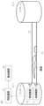
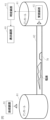
- the system of this embodiment includes a transmitting device 91, a receiving device 92, a determining device 93, and a display device 95.
- the transmitting device 91 is a device that continuously or periodically transmits radio waves that can propagate through a pipeline 82.
- the receiving device 92 is a device that receives radio waves from the pipeline 82.
- the determining device 93 is a device that determines the continuity of the pipeline 82 based on the reception result by the receiving device 92.
- the display device 95 is a device that displays the determination result of the determining device 93.
- the display device 95 may be provided in the determining device 93.
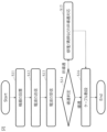
- FIG. 2 shows an example of a work flow on site.
- S11 A transmitting device 91 and a receiving device 92 are installed in manholes 81-1 and 81-2 located at both ends of a pipeline 82.
- S12 The transmitter 91 transmits radio waves toward the pipeline 82.
- S13 The receiving device 92 receives the radio waves from the pipeline 82. As a result, the receiving device 92 receives the radio waves that have passed through the pipeline 82.
- S ⁇ b>14 The determination device 93 determines the continuity of the pipe 82 based on the signal received by the receiving device 92 .
- S15 If there is no continuity (non-continuity in S14), the determination device 93 outputs a message indicating that there is no continuity to the display device 95.
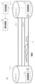
- step S11 as shown in FIG. 1, an example is shown in which a transmitting device 91 is installed in manhole 81-1 and a receiving device 92 is installed in manhole 81-2.
- the transmitting device 91 and the receiving device 92 are installed at both ends of the pipeline 82. Therefore, in step S12, the transmitting device 91 transmits radio waves that can propagate the entire length of the pipeline 82. Then, in step S13, the receiving device 92 receives the radio waves after they have propagated the entire length of the pipeline 82.
- the transmitting device 91 executes step S12
- the receiving device 92 executes step S13
- the determining device 93 executes step S14.
- the determination in step S14 can be made by any method capable of determining the continuity state of radio waves in the pipeline 82.
- the determining device 93 determines that there is continuity when the received power is greater than the noise power, and determines that there is no continuity when the received power is equal to or less than the noise power.
- the loss of radio waves propagating within the pipe 82 can be found using arithmetic processing.
- a threshold value can be determined using arithmetic processing, and this can be used to determine continuity.
- the determination device 93 determines continuity when the received power is greater than the threshold value, and determines non-conduction when the received power is equal to or less than the threshold value.
- Examples of arithmetic processing for finding the threshold value include simulation and calculation of free space propagation loss. In this case, a propagation loss model within the waveguide that also takes into account attenuation due to corrosion can be used, and noise power can also be taken into account.
- radio waves of any frequency can be used.
- the frequency of the radio waves may be a single frequency or may include multiple frequencies. It may also be a discrete frequency in a predetermined band or a continuous frequency. It may also be for radar or communication.
- the received power used in step S14 may be calculated by the receiving device 92 or by the determination device 93.
- averaging processing or statistical processing may be performed.
- the determination device 93 may be a separate device from the receiving device 92, or may be the same device. If they are separate devices, the output from the receiving device 92 to the determination device 93 may be made using a wireless connection such as radio waves, or may be made using a wired connection.
- the conductivity determination is performed using radio waves, so it is possible to confirm that the conduit 82 between manholes 81-1 and 81-2 is conductive without inserting a pipe camera into the conduit 82.
- a transmitting device 91 and a receiving device 92 are both installed in a manhole 81-1 located at one end of a pipeline 82.
- step S11 both the transmitting device 91 and the receiving device 92 are installed at one end of the pipeline 82. Therefore, in step S12, the transmitting device 91 transmits radio waves that can travel back and forth through the pipeline 82. Then, in step S13, the receiving device 92 receives the radio waves reflected within the pipeline 82.
- the judgment in step S14 can be made by any method capable of judging the reflection state of radio waves in the pipeline 82. For example, if the received power is greater than the noise power, it is judged as non-conductive, and if the received power is equal to or less than the noise power, it is judged as conductive. Instead of noise power, a threshold value or the like may be used as in the first embodiment.
- An obstacle 70 is present at the position in the pipeline 82 where the radio waves are reflected.
- the time from when the transmitter 91 transmits the radio waves until the radio waves are reflected by the obstacle 70 corresponds to the distance from the transmitter 91 and the receiver 92 to the obstacle 70. Therefore, by employing this embodiment, the position where the obstacle 70 exists can be identified.
- the transmitting device 91, the receiving device 92, the determining device 93, and the display device 95 may be separate devices, or may be the same device.
- a radio signal having a plurality of polarization states is used as the radio wave in the first embodiment.
- Transmitting device 91 is a device capable of transmitting radio signals having multiple polarizations.
- Receiving device 92 is a device capable of receiving radio signals having multiple polarizations.
- step S12 the transmitting device 91 transmits a radio signal having multiple polarizations
- step S13 the receiving device 92 receives the radio signal having multiple polarizations.
- step S14 if the received power is greater than the noise power in any of the polarization combinations, continuity is determined, and if the received power is equal to or less than the noise power in any of the polarization combinations, non-continuity is determined.
- the transmitting device 91 may transmit radio signals with different polarizations at different times, or may transmit radio signals with different polarizations in a superimposed manner.
- the receiving device 92 may receive radio signals with different polarizations at different times, or may receive radio signals with different polarizations in a separated manner.
- the determination is made using a combination of polarizations, so multiple types of wireless signals can be sent and received simultaneously.
- FIG. 1 An example of a system configuration of this embodiment is shown in Fig. 1.
- radio signals of different frequencies are used as the radio waves in the first embodiment.
- the multiple frequencies include a first frequency and a second frequency that are predetermined, and the first frequency is higher than the second frequency.
- Transmitting device 91 is a device capable of transmitting radio signals of multiple frequencies.
- Receiving device 92 is a device capable of receiving radio signals of multiple frequencies.
- step S12 the transmitting device 91 transmits radio signals of multiple frequencies
- step S13 the receiving device 92 receives the radio signals of multiple frequencies.
- step S14 the determining device 93 determines continuity based on the multiple frequencies.
- step S14 The continuity determination in step S14 is performed, for example, in the following order.
- Step S21 If the received power is greater than the noise power at all frequencies, it is determined that there is continuity.
- Step S22 If the received power is greater than the noise power at frequencies equal to or greater than the first frequency and the received power is equal to or less than the noise power at frequencies less than the first frequency, it is determined that there is continuity.
- Step S23 If the received power is greater than the noise power at frequencies equal to or greater than the second frequency and the received power is equal to or less than the noise power at frequencies less than the second frequency, it is determined that there is no continuity.
- Step S24 If the received power is equal to or less than the noise power at all frequencies, it is determined that there is no continuity.
- the first frequency and the second frequency are set to values that depend on the diameter of the pipeline 82 and the size of the gap within the pipeline 82.
- the determination device 93 can determine the size of the gap within the pipeline 82.
- step S14 by checking the continuity in step S14 from high frequencies, it is possible to quickly confirm that continuity exists.
- first frequency and the second frequency may be values that depend on noise power, instead of or in addition to the values that depend on the diameter of the pipe 82 and the size of the gap within the pipe 82.
- the present disclosure is not limited to steps S21 to S24, and the continuity/non-continuity index may be calculated by weighting according to frequency and adding up the received power at all frequencies.
- the determination device 93 can determine the size of the gap inside the pipeline 82. This makes it possible to determine whether or not the inside of the pipeline 82 needs to be cleaned.
- FIG. 4 An example of the system configuration of this embodiment is shown in Fig. 4.
- a plurality of pipes 82-1 to 82-N are connected in parallel between manholes 81-1 and 81-2.
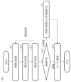
- FIG. 5 shows an example of the judgment flow.
- steps S11 to S13 are repeatedly executed for each pipeline 82. Then, when steps S11 to S13 are completed for all pipelines 82, step S14 is executed.
- the judgment device 93 judges the pipeline 82 with the highest conductivity.
- the pipeline 82 with the highest conductivity is, for example, the pipeline 82 with the highest received power, or the pipeline 82 with the received power farthest from the noise power or the threshold value.
- a transmitter 91 is placed on the ground outside a manhole 81-1.
- the radio waves transmitted from the transmitting device 91 are repeatedly reflected and propagate through the pipe 82. Therefore, by receiving the radio waves at the receiving device 92, the same action and effect as in the first embodiment can be obtained.
- step S11 there is no need to install the transmitter 91 inside the manhole 81-1 in step S11, which simplifies the work in step S11.
- step S11 an example is shown in which only the transmitting device 91 is placed on the ground outside the manhole 81-1, but the receiving device 92 may also be placed on the ground outside the manhole 81-1 in step S11.
- the determination device 93 of the present invention can also be realized by a computer and a program, and the program can be recorded on a recording medium or provided through a network.
- the program of the present disclosure is a program for causing a computer to realize each function of the determination device 93 according to the present disclosure, and is a program for causing a computer to execute each procedure of the method executed by the determination device 93 according to the present disclosure.
- the configuration aspects of the third to sixth embodiments may be adopted in the second embodiment.
Landscapes
- Life Sciences & Earth Sciences (AREA)
- Physics & Mathematics (AREA)
- Health & Medical Sciences (AREA)
- General Physics & Mathematics (AREA)
- Chemical & Material Sciences (AREA)
- Analytical Chemistry (AREA)
- Biochemistry (AREA)
- General Health & Medical Sciences (AREA)
- Electromagnetism (AREA)
- Immunology (AREA)
- Pathology (AREA)
- Engineering & Computer Science (AREA)
- Hydrology & Water Resources (AREA)
- Public Health (AREA)
- Water Supply & Treatment (AREA)
- Pipeline Systems (AREA)
Abstract
La présente divulgation concerne un système comprenant : un dispositif de transmission qui transmet des ondes radio qui peuvent se propager à travers un pipeline ; un dispositif de réception qui reçoit les ondes radio provenant du pipeline ; et un dispositif de détermination qui détermine la continuité du pipeline sur la base des résultats de la réception par le dispositif de réception.
Priority Applications (2)
| Application Number | Priority Date | Filing Date | Title |
|---|---|---|---|
| PCT/JP2023/021352 WO2024252617A1 (fr) | 2023-06-08 | 2023-06-08 | Système d'inspection de continuité pour pipeline enterré souterrain |
| JP2025525862A JPWO2024252617A1 (fr) | 2023-06-08 | 2023-06-08 |
Applications Claiming Priority (1)
| Application Number | Priority Date | Filing Date | Title |
|---|---|---|---|
| PCT/JP2023/021352 WO2024252617A1 (fr) | 2023-06-08 | 2023-06-08 | Système d'inspection de continuité pour pipeline enterré souterrain |
Publications (1)
| Publication Number | Publication Date |
|---|---|
| WO2024252617A1 true WO2024252617A1 (fr) | 2024-12-12 |
Family
ID=93795636
Family Applications (1)
| Application Number | Title | Priority Date | Filing Date |
|---|---|---|---|
| PCT/JP2023/021352 Ceased WO2024252617A1 (fr) | 2023-06-08 | 2023-06-08 | Système d'inspection de continuité pour pipeline enterré souterrain |
Country Status (2)
| Country | Link |
|---|---|
| JP (1) | JPWO2024252617A1 (fr) |
| WO (1) | WO2024252617A1 (fr) |
Citations (4)
| Publication number | Priority date | Publication date | Assignee | Title |
|---|---|---|---|---|
| JPH1068717A (ja) * | 1996-08-28 | 1998-03-10 | Unisia Jecs Corp | 燃料性状判別装置 |
| JPH11243123A (ja) * | 1998-11-02 | 1999-09-07 | Hitachi Ltd | 半導体デバイスの生産方法とその製造装置 |
| JP2002195959A (ja) * | 2001-11-12 | 2002-07-10 | Hitachi Ltd | 半導体デバイスの検査方法 |
| JP2022161052A (ja) * | 2021-04-08 | 2022-10-21 | パナソニックIpマネジメント株式会社 | 超音波流量計 |
-
2023
- 2023-06-08 JP JP2025525862A patent/JPWO2024252617A1/ja active Pending
- 2023-06-08 WO PCT/JP2023/021352 patent/WO2024252617A1/fr not_active Ceased
Patent Citations (4)
| Publication number | Priority date | Publication date | Assignee | Title |
|---|---|---|---|---|
| JPH1068717A (ja) * | 1996-08-28 | 1998-03-10 | Unisia Jecs Corp | 燃料性状判別装置 |
| JPH11243123A (ja) * | 1998-11-02 | 1999-09-07 | Hitachi Ltd | 半導体デバイスの生産方法とその製造装置 |
| JP2002195959A (ja) * | 2001-11-12 | 2002-07-10 | Hitachi Ltd | 半導体デバイスの検査方法 |
| JP2022161052A (ja) * | 2021-04-08 | 2022-10-21 | パナソニックIpマネジメント株式会社 | 超音波流量計 |
Also Published As
| Publication number | Publication date |
|---|---|
| JPWO2024252617A1 (fr) | 2024-12-12 |
Similar Documents
| Publication | Publication Date | Title |
|---|---|---|
| EP4361590B1 (fr) | Améliorations apportées ou se rapportant à la surveillance de tuyaux de fluide | |
| US10209225B2 (en) | Sound propagation comparison with automated frequency selection for pipe condition assessment | |
| US10690630B2 (en) | Generation and utilization of pipe-specific sound attenuation | |
| US20180308265A1 (en) | Graphical mapping of pipe node location selection | |
| CN114110443B (zh) | 一种输流管道奇点特征智能检测方法 | |
| ZA202303495B (en) | Device and method for managing resources for monitoring elongate structures | |
| CN109737307A (zh) | 一种城市雨污水管网错接漏接快速排查系统和方法 | |
| CN104796191B (zh) | 一种传输装置 | |
| WO2024252617A1 (fr) | Système d'inspection de continuité pour pipeline enterré souterrain | |
| CN108731743A (zh) | 基于ofdr分布式光纤的排水管道在线监测系统及方法 | |
| JP3400255B2 (ja) | 配管設備の異常検出方法及び異常診断装置 | |
| WO2024252618A1 (fr) | Système d'inspection de continuité pour pipeline enterré souterrain | |
| CN215908883U (zh) | 一种适用于长距离海管泄漏监测的传感器 | |
| CN108759936A (zh) | 基于ofdr分布式光纤的排水管道监测补偿系统及方法 | |
| CN101743695A (zh) | 用于在管道系统中传输数据的网络和方法 | |
| WO2024252621A1 (fr) | Procédé d'inspection pour pipeline enterré souterrain | |
| US12105233B2 (en) | System and method for acoustically detecting cross bores | |
| CN111765390A (zh) | 基于声发射响应的管道漏点定位方法及系统 | |
| CN117908090A (zh) | 一种光纤微动地质勘察装置及方法 | |
| WO2024252619A1 (fr) | Procédé de réglage d'itinéraire pour câble de pose | |
| Khan | An acoustic based approach for mitigating sewer system overflows | |
| CN205139389U (zh) | 示踪装置及具有该示踪装置的管线装置 | |
| CN223551917U (zh) | 一种用于寻找管道光缆的熔接盒 | |
| CN115235421A (zh) | 基于分布式光纤的管道沉降监测装置 | |
| JP4641909B2 (ja) | 配管系統識別方法および配管系統識別システム |
Legal Events
| Date | Code | Title | Description |
|---|---|---|---|
| 121 | Ep: the epo has been informed by wipo that ep was designated in this application |
Ref document number: 23940715 Country of ref document: EP Kind code of ref document: A1 |
|
| ENP | Entry into the national phase |
Ref document number: 2025525862 Country of ref document: JP Kind code of ref document: A |
|
| NENP | Non-entry into the national phase |
Ref country code: DE |