WO2024252618A1 - Système d'inspection de continuité pour pipeline enterré souterrain - Google Patents
Système d'inspection de continuité pour pipeline enterré souterrain Download PDFInfo
- Publication number
- WO2024252618A1 WO2024252618A1 PCT/JP2023/021357 JP2023021357W WO2024252618A1 WO 2024252618 A1 WO2024252618 A1 WO 2024252618A1 JP 2023021357 W JP2023021357 W JP 2023021357W WO 2024252618 A1 WO2024252618 A1 WO 2024252618A1
- Authority
- WO
- WIPO (PCT)
- Prior art keywords
- microphone
- continuity
- pipeline
- speaker
- pipe
- Prior art date
- Legal status (The legal status is an assumption and is not a legal conclusion. Google has not performed a legal analysis and makes no representation as to the accuracy of the status listed.)
- Pending
Links
Images

Classifications
-
- E—FIXED CONSTRUCTIONS
- E03—WATER SUPPLY; SEWERAGE
- E03F—SEWERS; CESSPOOLS
- E03F7/00—Other installations or implements for operating sewer systems, e.g. for preventing or indicating stoppage; Emptying cesspools
-
- G—PHYSICS
- G01—MEASURING; TESTING
- G01N—INVESTIGATING OR ANALYSING MATERIALS BY DETERMINING THEIR CHEMICAL OR PHYSICAL PROPERTIES
- G01N29/00—Investigating or analysing materials by the use of ultrasonic, sonic or infrasonic waves; Visualisation of the interior of objects by transmitting ultrasonic or sonic waves through the object
Definitions
- This disclosure relates to technology for testing continuity of underground pipes.
- Fiber optic cables are installed on utility poles or in conduits, and are provided from the station to each home, etc.
- Non-Patent Document 1 Previously, pipe cameras were used to check for abnormalities in pipes to check the state of continuity (see, for example, Non-Patent Document 1).
- Non-Patent Document 1 may not be able to capture clear images, and the condition inside the pipeline may not be properly understood.
- the continuity inspection in Non-Patent Document 1 requires a worker to enter a manhole connecting the pipeline to the ground and insert a pipe camera into the pipeline, which requires work.
- the purpose of this disclosure is to make it possible to perform continuity testing of a pipeline without inserting a pipe camera into the pipeline.
- the system of the present disclosure comprises: A speaker that outputs a sound wave that can propagate through the pipe; a microphone for detecting the sound waves from the pipe; a determination device that determines continuity of the pipeline based on a detection result by the microphone; and performing the method of the present disclosure.
- the system disclosed herein can employ a first aspect in which the speaker and the microphone are installed at both ends of the pipeline.
- the speaker outputs sound waves that can propagate the entire length of the pipeline.
- the microphone detects the sound waves after they have propagated the entire length of the pipeline.
- the system disclosed herein may adopt a second aspect in which the speaker and the microphone are installed at one end of the pipeline.
- the speaker outputs sound waves that can travel back and forth through the pipeline.
- the microphone may detect sound waves reflected by an obstacle in the pipeline.
- the determination device may determine the continuity of the pipe based on the sound volume detected by the microphone.
- the continuity is determined when the sound volume detected by the microphone is greater than a predetermined threshold, and the non-continuity is determined when the sound volume detected by the microphone is equal to or less than the threshold.
- the continuity is determined when the sound volume detected by the microphone is less than a predetermined threshold, and the non-continuity is determined when the sound volume detected by the microphone is equal to or greater than the threshold.
- This disclosure makes it possible to inspect the continuity of pipelines between manholes without inserting a pipe camera into the pipeline.
- 1 is an example embodiment of a system of the present disclosure. 13 shows an example of a determination flow. 1 is an example embodiment of a system of the present disclosure. 1 is an example embodiment of a system of the present disclosure. 13 shows an example of a determination flow. 1 is an example embodiment of a system of the present disclosure. 1 is an example embodiment of a system of the present disclosure.
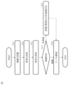
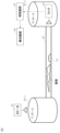
- (First embodiment) 1 shows an example of a system configuration of this embodiment.
- the system of this embodiment includes a speaker 91, a microphone 92, a determination device 93, and a display device 95.
- the speaker 91 is a device that continuously or periodically outputs sound waves that can propagate through the pipeline 82.
- the microphone 92 is a device that detects sound waves from the pipeline 82.
- the determination device 93 is a device that determines the continuity of the pipeline 82 based on a detection signal from the microphone 92.
- the display device 95 is a device that displays the determination result of the determination device 93.
- the display device 95 may be provided in the determination device 93.
- FIG. 2 shows an example of a work flow on site.
- S11 A speaker 91 and a microphone 92 are installed in manholes 81-1 and 81-2 located at both ends of a pipeline 82.
- S12 The speaker 91 outputs sound waves toward the pipe 82.
- S13 The microphone 92 detects the sound waves from the pipe 82. As a result, the microphone 92 detects the sound waves that have passed through the pipe 82.
- S 14 The determination device 93 determines the continuity of the pipe 82 based on the detection signal detected by the microphone 92 .
- S15 If there is no continuity (non-continuity in S14), the determination device 93 outputs a message indicating that there is no continuity to the display device 95.
- step S11 as shown in FIG. 1, an example is shown in which a speaker 91 is installed in manhole 81-1 and a microphone 92 is installed in manhole 81-2.
- the speaker 91 and the microphone 92 are installed at both ends of the pipeline 82. Therefore, in step S12, the speaker 91 outputs sound waves that can propagate the entire length of the pipeline 82. Then, in step S13, the microphone 92 receives the sound waves after they have propagated the entire length of the pipeline 82.
- the speaker 91 executes step S12
- the microphone 92 executes step S13
- the determination device 93 executes step S14.
- the determination in step S14 can be made by any method capable of determining the continuity state of sound waves in the pipeline 82.
- the determination device 93 determines that there is continuity when the volume detected by the microphone 92 is greater than noise, and determines that there is no continuity when the volume is equal to or less than noise.
- the loss of the sound waves propagating within the pipe 82 can be found using arithmetic processing.
- a threshold value can be determined using arithmetic processing, and this can be used to determine continuity.
- the determination device 93 determines that there is continuity if the volume detected by the microphone 92 is greater than the threshold value, and determines that there is no continuity if the volume detected by the microphone 92 is equal to or less than the threshold value.
- Examples of arithmetic processing for finding the threshold value include simulation and calculation of free space propagation loss. In this case, a propagation loss model within the waveguide that also takes into account attenuation due to corrosion can be used, and noise can also be taken into account.
- the frequency of the sound waves may be a single frequency or may include multiple frequencies.
- the frequency may be discrete frequencies in a predetermined band, or may be a continuous frequency.
- the volume used in step S14 may be measured by the microphone 92 or by the determination device 93. When measuring the volume, averaging or statistical processing may be performed.
- the determination device 93 may be a separate device from the microphone 92, or may be the same device. If they are separate devices, the output from the microphone 92 to the determination device 93 may be made using a wireless connection such as radio waves, or may be made using a wired connection.
- continuity determination is performed using sound waves, making it possible to confirm that the conduit 82 between manholes 81-1 and 81-2 is continuum without inserting a pipe camera into the conduit 82.
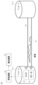
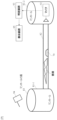
- a speaker 91 and a microphone 92 are both installed in a manhole 81-1 located at one end of a pipeline 82.
- step S11 both the speaker 91 and the microphone 92 are installed at one end of the pipeline 82. Therefore, in step S12, the speaker 91 outputs sound waves that can travel back and forth through the pipeline 82. Then, in step S13, the microphone 92 detects the sound waves reflected within the pipeline 82.
- the judgment in step S14 can be made by any method capable of judging the reflection state of sound waves in the pipe 82. For example, if the volume is greater than the noise, it is judged as non-conductive, and if the volume is equal to or less than the noise, it is judged as conductive. Instead of noise, a threshold value or the like may be used as in the first embodiment.
- An obstacle 70 is present at the position where the sound waves are reflected in the duct 82.
- the time from when the speaker 91 outputs the sound waves until the sound waves are reflected by the obstacle 70 corresponds to the distance from the speaker 91 and microphone 92 to the obstacle 70. Therefore, by adopting this embodiment, the position where the obstacle 70 exists can be identified.
- the speaker 91, microphone 92, determination device 93, and display device 95 may be separate devices, or may be the same device.
- Fig. 1 An example of a system configuration of this embodiment is shown in Fig. 1.
- sound waves of a plurality of different frequencies are used as the sound waves in the first embodiment.
- the plurality of frequencies include a first frequency and a second frequency that are predetermined, and the first frequency is higher than the second frequency.
- the speaker 91 is a device capable of outputting sound waves of multiple frequencies.
- the microphone 92 is a device capable of detecting sound waves of multiple frequencies.
- step S12 the speaker 91 outputs sound waves of multiple frequencies
- step S13 the microphone 92 detects the sound waves of multiple frequencies.
- step S14 the determination device 93 determines continuity based on the multiple frequencies.
- step S14 The continuity determination in step S14 is performed, for example, in the following order.
- Step S21 If the volume is greater than noise at all frequencies, it is determined that there is continuity.
- Step S22 If the volume is greater than noise at frequencies equal to or greater than a first frequency and is equal to or less than noise at frequencies less than the first frequency, it is determined that there is continuity.
- Step S23 If the volume is greater than noise at frequencies equal to or greater than the second frequency and is equal to or less than noise at frequencies less than the second frequency, it is determined that there is no continuity.
- Step S24 If the volume is equal to or less than noise at all frequencies, it is determined that there is no continuity.
- the first frequency and the second frequency are set to values that depend on the diameter of the pipeline 82 and the size of the gap within the pipeline 82.
- the determination device 93 can determine the size of the gap within the pipeline 82.
- step S14 by checking the continuity in step S14 from high frequencies, it is possible to quickly confirm that continuity exists.
- first frequency and the second frequency may be values that depend on noise, instead of or in addition to the values that depend on the diameter of the pipe 82 and the size of the gap within the pipe 82.
- the present disclosure is not limited to steps S21 to S24, and the continuity/non-continuity index may be calculated by weighting according to frequency and adding up the volume at all frequencies.
- the determination device 93 can determine the size of the gap inside the pipeline 82. Therefore, it can determine whether or not the inside of the pipeline 82 needs to be cleaned.
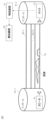
- FIG. 4 An example of the system configuration of this embodiment is shown in Fig. 4.
- a plurality of pipes 82-1 to 82-N are connected in parallel between manholes 81-1 and 81-2.
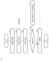
- FIG. 5 shows an example of the judgment flow.
- steps S11 to S13 are repeatedly executed for each pipeline 82. Then, when steps S11 to S13 are completed for all pipelines 82, step S14 is executed.
- the judgment device 93 judges the pipeline 82 with the highest conductivity.
- the pipeline 82 with the highest conductivity is, for example, the pipeline 82 with the loudest volume, or the pipeline 82 whose volume is farthest from noise or a threshold value.
- a speaker 91 is disposed on the ground outside a manhole 81-1.
- the sound waves output from the speaker 91 are repeatedly reflected and propagate through the pipe 82. Therefore, by detecting the sound waves with the microphone 92, the same action and effect as in the first embodiment can be obtained.
- step S11 there is no need to install the speaker 91 inside the manhole 81-1 in step S11, which simplifies the work in step S11.
- sound waves may be generated in the manhole 81-1 by, for example, hitting the lid 83 of the manhole 81-1 with a hammer 94. Also, instead of using the speaker 91, the sound generated when a vehicle passes over the lid 83 of the manhole 81-1 may be used.
- step S11 an example is shown in which only the speaker 91 is placed on the ground outside the manhole 81-1, but in step S11, the microphone 92 may also be placed on the ground outside the manhole 81-1.
- the determination device 93 of the present invention can also be realized by a computer and a program, and the program can be recorded on a recording medium or provided through a network.
- the program of the present disclosure is a program for causing a computer to realize each function of the determination device 93 according to the present disclosure, and is a program for causing a computer to execute each procedure of the method executed by the determination device 93 according to the present disclosure.
- the configuration aspects of the third to fifth embodiments may be adopted in the second embodiment.
Landscapes
- Life Sciences & Earth Sciences (AREA)
- Health & Medical Sciences (AREA)
- General Health & Medical Sciences (AREA)
- Chemical & Material Sciences (AREA)
- Analytical Chemistry (AREA)
- Biochemistry (AREA)
- Physics & Mathematics (AREA)
- General Physics & Mathematics (AREA)
- Immunology (AREA)
- Pathology (AREA)
- Engineering & Computer Science (AREA)
- Hydrology & Water Resources (AREA)
- Public Health (AREA)
- Water Supply & Treatment (AREA)
- Investigating Or Analyzing Materials By The Use Of Ultrasonic Waves (AREA)
Abstract
La présente divulgation concerne un système comprenant : un haut-parleur qui émet des ondes sonores qui peuvent se propager à travers un pipeline ; un microphone qui détecte les ondes sonores provenant du pipeline ; et un dispositif de détermination qui détermine la continuité du pipeline sur la base des résultats de la détection par le microphone.
Priority Applications (2)
| Application Number | Priority Date | Filing Date | Title |
|---|---|---|---|
| JP2025525863A JPWO2024252618A1 (fr) | 2023-06-08 | 2023-06-08 | |
| PCT/JP2023/021357 WO2024252618A1 (fr) | 2023-06-08 | 2023-06-08 | Système d'inspection de continuité pour pipeline enterré souterrain |
Applications Claiming Priority (1)
| Application Number | Priority Date | Filing Date | Title |
|---|---|---|---|
| PCT/JP2023/021357 WO2024252618A1 (fr) | 2023-06-08 | 2023-06-08 | Système d'inspection de continuité pour pipeline enterré souterrain |
Publications (1)
| Publication Number | Publication Date |
|---|---|
| WO2024252618A1 true WO2024252618A1 (fr) | 2024-12-12 |
Family
ID=93795655
Family Applications (1)
| Application Number | Title | Priority Date | Filing Date |
|---|---|---|---|
| PCT/JP2023/021357 Pending WO2024252618A1 (fr) | 2023-06-08 | 2023-06-08 | Système d'inspection de continuité pour pipeline enterré souterrain |
Country Status (2)
| Country | Link |
|---|---|
| JP (1) | JPWO2024252618A1 (fr) |
| WO (1) | WO2024252618A1 (fr) |
Citations (3)
| Publication number | Priority date | Publication date | Assignee | Title |
|---|---|---|---|---|
| JPH1068717A (ja) * | 1996-08-28 | 1998-03-10 | Unisia Jecs Corp | 燃料性状判別装置 |
| JP2001201488A (ja) * | 2000-01-19 | 2001-07-27 | Furekkusuai:Kk | コンクリート打設箇所の検査装置および検査方法 |
| JP2022161052A (ja) * | 2021-04-08 | 2022-10-21 | パナソニックIpマネジメント株式会社 | 超音波流量計 |
-
2023
- 2023-06-08 WO PCT/JP2023/021357 patent/WO2024252618A1/fr active Pending
- 2023-06-08 JP JP2025525863A patent/JPWO2024252618A1/ja active Pending
Patent Citations (3)
| Publication number | Priority date | Publication date | Assignee | Title |
|---|---|---|---|---|
| JPH1068717A (ja) * | 1996-08-28 | 1998-03-10 | Unisia Jecs Corp | 燃料性状判別装置 |
| JP2001201488A (ja) * | 2000-01-19 | 2001-07-27 | Furekkusuai:Kk | コンクリート打設箇所の検査装置および検査方法 |
| JP2022161052A (ja) * | 2021-04-08 | 2022-10-21 | パナソニックIpマネジメント株式会社 | 超音波流量計 |
Also Published As
| Publication number | Publication date |
|---|---|
| JPWO2024252618A1 (fr) | 2024-12-12 |
Similar Documents
| Publication | Publication Date | Title |
|---|---|---|
| US10209225B2 (en) | Sound propagation comparison with automated frequency selection for pipe condition assessment | |
| US10690630B2 (en) | Generation and utilization of pipe-specific sound attenuation | |
| US10565752B2 (en) | Graphical mapping of pipe node location selection | |
| CN103733040A (zh) | 管道的监测 | |
| CN108254798B (zh) | 一种快速定位地下光缆的方法及装置 | |
| CN114110443B (zh) | 一种输流管道奇点特征智能检测方法 | |
| JP4172241B2 (ja) | 配管の漏洩位置検知方法および装置 | |
| Wu et al. | Pre-existing concrete pipe disconnection detection based on fiber-optic distributed acoustic sensing | |
| WO2024252618A1 (fr) | Système d'inspection de continuité pour pipeline enterré souterrain | |
| KR102875024B1 (ko) | 광 케이블 경로 식별 장치 및 방법 | |
| WO2024252617A1 (fr) | Système d'inspection de continuité pour pipeline enterré souterrain | |
| JP3805084B2 (ja) | 浸水状態検査方法及び検査装置 | |
| JPH11142280A (ja) | 管路検査方法 | |
| US12105233B2 (en) | System and method for acoustically detecting cross bores | |
| Khan | Empirical Modeling of Acoustic Signal Attenuation in Municipal Sewer Pipes for Condition Monitoring Applications | |
| WO2024252621A1 (fr) | Procédé d'inspection pour pipeline enterré souterrain | |
| Khan | An acoustic based approach for mitigating sewer system overflows | |
| RU2503937C1 (ru) | Способ определения расстояния до места течи подземного трубопровода и устройство для его реализации | |
| WO2024252619A1 (fr) | Procédé de réglage d'itinéraire pour câble de pose | |
| Wu et al. | Detecting pre-existing HDPE double-wall corrugated drainage pipe disconnection with fiber-optic distributed acoustic sensing | |
| JP4641909B2 (ja) | 配管系統識別方法および配管系統識別システム | |
| JP7671317B2 (ja) | 埋設物予防保全システム及び埋設物予防保全方法 | |
| CN223551917U (zh) | 一种用于寻找管道光缆的熔接盒 | |
| WO2015194138A1 (fr) | Dispositif de spécification de position, système de spécification de position, procédé de spécification de position et support d'enregistrement lisible par ordinateur | |
| Bin Ali | Development of acoustic sensor and signal processing technique. |
Legal Events
| Date | Code | Title | Description |
|---|---|---|---|
| 121 | Ep: the epo has been informed by wipo that ep was designated in this application |
Ref document number: 23940716 Country of ref document: EP Kind code of ref document: A1 |
|
| ENP | Entry into the national phase |
Ref document number: 2025525863 Country of ref document: JP Kind code of ref document: A |
|
| NENP | Non-entry into the national phase |
Ref country code: DE |