WO2024252621A1 - 地中埋設管路の調査方法 - Google Patents
地中埋設管路の調査方法 Download PDFInfo
- Publication number
- WO2024252621A1 WO2024252621A1 PCT/JP2023/021363 JP2023021363W WO2024252621A1 WO 2024252621 A1 WO2024252621 A1 WO 2024252621A1 JP 2023021363 W JP2023021363 W JP 2023021363W WO 2024252621 A1 WO2024252621 A1 WO 2024252621A1
- Authority
- WO
- WIPO (PCT)
- Prior art keywords
- pipeline
- database
- propagation
- waves
- camera
- Prior art date
- Legal status (The legal status is an assumption and is not a legal conclusion. Google has not performed a legal analysis and makes no representation as to the accuracy of the status listed.)
- Pending
Links
Images


Classifications
-
- E—FIXED CONSTRUCTIONS
- E03—WATER SUPPLY; SEWERAGE
- E03F—SEWERS; CESSPOOLS
- E03F7/00—Other installations or implements for operating sewer systems, e.g. for preventing or indicating stoppage; Emptying cesspools
-
- G—PHYSICS
- G01—MEASURING; TESTING
- G01N—INVESTIGATING OR ANALYSING MATERIALS BY DETERMINING THEIR CHEMICAL OR PHYSICAL PROPERTIES
- G01N22/00—Investigating or analysing materials by the use of microwaves or radio waves, i.e. electromagnetic waves with a wavelength of one millimetre or more
Definitions
- This disclosure relates to technology for estimating conditions inside pipelines buried underground.
- Fiber optic cables are installed on utility poles or in conduits, and are provided from station buildings to individual homes, etc.
- Non-Patent Document 1 Previously, pipe cameras were used to check for abnormalities in pipes to check the state of continuity (see, for example, Non-Patent Document 1).
- Visual continuity inspections using cameras can visually check for the presence of obstacles in the pipeline, but there is a problem in that it is difficult to determine what type of obstacle is present just by looking. In particular, because the water that has entered the pipeline is mixed with soil and sand, there is a problem in that it is difficult to determine the presence of rust inside the pipeline.
- the purpose of this disclosure is to make it possible to estimate the conditions inside a pipeline.
- Obstacles in pipelines can be soil, water, or rust.
- the behavior of radio waves, sound waves, light, etc. in pipelines where such obstacles exist varies and can be measured in advance. Therefore, this disclosure makes it possible to estimate the condition inside the pipeline based on at least one of the propagation characteristics and reflection characteristics inside the pipeline.
- the system disclosed herein includes a database that stores at least one of the propagation characteristics and reflection characteristics within a pipeline for each type of obstacle present within the pipeline, and a computing device that estimates the condition within the pipeline based on the database, and executes the method disclosed herein.
- the system of the present disclosure may include a measuring device that measures the propagation characteristics or reflection characteristics within the pipeline.
- the computing device may estimate the condition within the pipeline by comparing the measurement results from the measuring device with the database.
- the database may store the propagation or reflection characteristics of at least one of radio waves, sound waves, or light waves.
- the database may store the propagation or reflection characteristics of a plurality of different frequencies.
- the types of obstacles may include at least one of soil, water, and rust.
- the system disclosed herein includes a transmitting device that transmits radio waves, and the measuring device receives the radio waves transmitted from the transmitting device.
- the transmitting device may transmit multiple radio waves with different frequencies.
- the measuring device may receive multiple radio waves with different frequencies.
- the system disclosed herein includes a transmitting device that transmits sound waves, and the measuring device receives the sound waves transmitted from the transmitting device.
- the transmitting device may transmit multiple sound waves with different frequencies.
- the measuring device may receive multiple sound waves with different frequencies.
- the system disclosed herein includes a transmitting device that transmits light waves, and the measuring device receives the light waves transmitted from the transmitting device.
- the transmitting device may transmit multiple light waves with different frequencies.
- the measuring device may receive multiple light waves with different frequencies.
- the system disclosed herein may include a camera capable of capturing images of the inside of the pipeline, and a display device that displays the images captured by the camera and the estimation results of the computing device.
- the system disclosed herein may include a transmitting device that transmits at least one of radio waves, sound waves, and light waves, and the transmitting device may be mounted on the camera.
- This disclosure makes it possible to estimate the conditions inside a pipeline.
- 1 is an example embodiment of a system of the present disclosure. An example of a method for estimating the state inside a pipeline will be described. An example of information stored in the database is shown below. 1 is an example embodiment of a system of the present disclosure. 1 is an example embodiment of a system of the present disclosure.
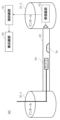
- FIG. 1 shows an example of a system configuration of this embodiment.
- the system of this embodiment includes a transmitting device 91, a receiving device 92, a computing device 93, and a display device 95.
- the transmitting device 91 is a device that transmits radio waves continuously or periodically.
- the receiving device 92 is a device that receives radio waves and functions as the "measuring instrument" of this disclosure.
- the computing device 93 is a device that estimates the state inside the pipeline 82 based on the reception result of the receiving device 92.
- the display device 95 is a device that displays the determination result of the determination device 93.
- the display device 95 may be provided in the determination device 93.
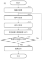
- FIG. 2 shows an example of a method for estimating the state inside a pipeline.
- S11 A transmitting device 91 and a receiving device 92 are installed in manholes 81-1 and 81-2 located at both ends of a pipeline 82.
- S12 The transmitter 91 transmits radio waves toward the pipeline 82.
- S13 The receiving device 92 receives the radio waves from the pipeline 82. As a result, the receiving device 92 receives the radio waves that have passed through the pipeline 82.
- S14 The receiving device 92 outputs the reception result to the calculation device 93.
- the reception result of the receiving device 92 is, for example, the reception strength of the radio wave.
- the radio waves transmitted and received in steps S12 and S13 are, for example, radio signals of different frequency bands.
- the transmitting device 91 transmits radio signals of frequency bands of 5 GHz, 30 GHz, and 60 GHz, which have different degrees of attenuation in water.
- the frequency band of the radio waves may be selected according to the diameter of the pipe 82; for example, the larger the diameter, the lower the frequency band that is used.
- the propagation attenuation of radio waves according to the type and amount of obstacles 70, such as dirt, water, and rust, present in the pipeline 82 is measured in advance and stored in a database provided in the computing device 93.
- a database provided in the computing device 93.
- four patterns of measurement results are stored in advance for each frequency: received power when the obstacle 70 is dirt and corrosion (rust), received power when the obstacle 70 is corrosion (rust) and water, received power when the obstacle 70 is dirt and water, and received power when the obstacle 70 is dirt, corrosion (rust) and water.
- the computing device 93 refers to the database, combines the measurement results of steps S11 to S14, and estimates the type of obstacle 70 that may be present in the pipeline 82, such as dirt, water, and rust. As a result, the type of obstacle 70 that may be present in the pipeline 82 is displayed on the display device 95.
- the calculation device 93 may estimate the amount of obstacles 70 in addition to the type of obstacles 70.
- the calculation device 93 may also estimate the percentage of the cavity in the pipeline 82 that is occupied by obstacles 70. Furthermore, for each type or combination of obstacles 70, it may be defined that a certain percentage or more of the obstacles 70 present in the pipeline 82 must exist to cause non-conduction. The calculation device 93 may then calculate the percentage probability of non-conduction based on the signal reception strength.
- the computing device 93 may determine the pipeline 82 with the highest conductivity possibility based on the reception strength and the amount of each obstacle 70. For example, when there is an equal amount of soil, water, and rust, the pipeline 82 with water may be selected as the pipeline with the highest conductivity possibility.
- steps S12 to S14 may be repeated from the installation of the transmitting device 91 and the receiving device 92 (S11).
- a signal other than radio waves such as sound waves or light
- the position of the transmitting device 91 and the receiving device 92 may be swapped and measurements may be performed again.
- the reflection characteristics reflected within the pipeline 82 may be measured.
- the system of this embodiment can classify and determine the quantity of obstacles in the pipeline 82 from a combination of the strengths of the received signals of multiple signals acquired using the receiving device 92, without using a pipe camera. Therefore, the system of this embodiment can easily perform continuity inspections and inspections of the condition inside the pipeline.
- the system of the present disclosure may include a blower and an anemometer.
- the blower is used to send air into the duct 82 from the transmitting device 91 side
- the anemometer is used to measure wind force on the receiving device 92 side, and the measurement result is output to the computing device 93. This can improve the estimation accuracy in the computing device 93.
- the system of the present disclosure may also include a blower, an anemometer, and a thermometer.
- the blower is used to send hot air from the transmitting device 91 into the duct 82
- the thermometer is used to measure the temperature on the receiving device 92 side
- the anemometer is used to measure the wind force, and these measurement results are output to the computing device 93. This can improve the estimation accuracy in the computing device 93.
- the system of this embodiment includes a pipe camera 94 in addition to the configuration of the first embodiment.
- An image captured by the pipe camera 94 is transmitted to a calculation device 93 and displayed on a display device 95.
- the system of this embodiment allows the image of the inside of the pipeline 82 captured by the pipe camera 94 to be viewed on the display device 95.
- Inspection of the pipeline 82 using the pipe camera 94 is performed, for example, before steps S11 to S14 in the first embodiment. At this time, if the type of obstacle 70 cannot be determined, the type of obstacle 70 can be estimated by performing steps S11 to S14 in the first embodiment.
- (Fourth embodiment) 5 shows an example of the system configuration of this embodiment.
- the transmitter 91 of the first embodiment is mounted on the tip of a pipe camera 94.
- the accuracy of classifying and measuring the quantity of obstacles 70 in the pipeline 82 can be improved by combining the images from the pipe camera 94 and the reception results of multiple signals acquired using the receiving device 92.
- the arithmetic device 93 of the present invention can also be realized by a computer and a program, and the program can be recorded on a recording medium or provided via a network.
- the program of the present disclosure is a program for causing a computer to realize each function of the arithmetic device 93 according to the present disclosure, and is a program for causing a computer to execute each procedure of the method executed by the arithmetic device 93 according to the present disclosure.
Landscapes
- Life Sciences & Earth Sciences (AREA)
- Physics & Mathematics (AREA)
- Health & Medical Sciences (AREA)
- General Physics & Mathematics (AREA)
- Chemical & Material Sciences (AREA)
- Analytical Chemistry (AREA)
- Biochemistry (AREA)
- General Health & Medical Sciences (AREA)
- Electromagnetism (AREA)
- Immunology (AREA)
- Pathology (AREA)
- Engineering & Computer Science (AREA)
- Hydrology & Water Resources (AREA)
- Public Health (AREA)
- Water Supply & Treatment (AREA)
- Investigating Materials By The Use Of Optical Means Adapted For Particular Applications (AREA)
Abstract
本家事は、管路内を伝搬可能な振動を測定する測定器と、前記測定器での測定結果に基づいて、前記管路内の状態を推定する演算装置と、を備えるシステムである。
Description
本開示は、地中に埋設された管路内の状態を推定する技術に関する。
近年のインターネットトラヒック需要の高まりによって、より高速通信が可能な光ファイバケーブルの新設や置き換えが進んでいる。光ファイバケーブルは電柱又は管路を用いて敷設され、局舎から各家庭などに提供されている。
管路は地中に埋設されているため、管路内に土砂や水が溜まったり、亀裂が入ったりすることがある。また管路内に溜まった水や地中の水分によって腐食することもある。これらによって、管路内の導通状態が悪くなることがある。
従来は、管路内の導通状態の検査のために、パイプカメラにより異常箇所を確認していた(例えば、非特許文献1参照。)。
伊藤他,「点検結果を基にした機械学習による通信管路内面の腐食予測手法」AI・データサイエンス論文集 3巻J2号,2022
カメラによる視認導通検査は、管路内に障害物が存在することを視認できるが、視認だけではどのような障害物が存在するかの判別が難しい問題がある。特に管路内に侵入している水は土砂が混じっているため、管路内の錆びの存在を判別できない問題がある。
そこで、本開示は、管路内の状態を推定可能にすることを目的とする。
管路における障害物の種類は土砂、水、錆びのいずれかである。そして、このような障害物が存在する管路内での電波、音波、光などの挙動は異なり、予め測定可能である。そこで、本開示は、管路内での伝搬特性及び反射特性の少なくともいずれかに基づいて、管路内の状態を推定可能にする。
本開示のシステムは、管路内での伝搬特性及び反射特性の少なくともいずれかを、前記管路内に存在する障害物の種類ごとに格納するデータベースと、前記データベースに基づいて、前記管路内の状態を推定する演算装置と、を備え、本開示の方法を実行する。
本開示のシステムは、前記管路内での伝搬特性又は反射特性を測定する測定器を備えていてもよい。このとき、前記演算装置は、前記測定器での測定結果を前記データベースと照合することで、前記管路内の状態を推定してもよい。
前記データベースは、電波、音波又は光波の少なくともいずれかの伝搬特性又は反射特性を格納してもよい。前記データベースは、異なる複数の周波数の伝搬特性又は反射特性を格納してもよい。また前記障害物の種類は、土砂、水、及び錆びの少なくともいずれかを含む。
例えば、本開示のシステムは、電波を送信する送信装置を備え、前記測定器は、前記送信装置から送信された電波を受信する。この構成において、前記送信装置は、周波数の異なる複数の電波を送信してもよい。そして前記測定器は、周波数の異なる複数の電波を受信してもよい。
例えば、本開示のシステムは、音波を送信する送信装置を備え、前記測定器は、前記送信装置から送信された音波を受信する。この構成において、前記送信装置は、周波数の異なる複数の音波を送信してもよい。そして前記測定器は、周波数の異なる複数の音波を受信してもよい。
例えば、本開示のシステムは、光波を送信する送信装置を備え、前記測定器は、前記送信装置から送信された光波を受信する。この構成において、前記送信装置は、周波数の異なる複数の光波を送信してもよい。そして前記測定器は、周波数の異なる複数の光波を受信してもよい。
本開示のシステムは、前記管路内を撮像可能なカメラと、前記カメラで撮像された画像、及び前記演算装置の推定結果を表示する表示装置と、を備えていてもよい。
本開示のシステムは、電波、音波又は光波の少なくともいずれかを送信する送信装置を備え、前記カメラに前記送信装置が搭載されていてもよい。
なお、上記各開示は、可能な限り組み合わせることができる。
本開示によれば、管路内の状態を推定可能にすることができる。
以下、本開示の実施形態について、図面を参照しながら詳細に説明する。なお、本開示は、以下に示す実施形態に限定されるものではない。これらの実施の例は例示に過ぎず、本開示は当業者の知識に基づいて種々の変更、改良を施した形態で実施することができる。なお、本明細書及び図面において符号が同じ構成要素は、相互に同一のものを示すものとする。
(第1の実施形態)
図1に、本実施形態のシステム構成例を示す。本実施形態のシステムは、送信装置91、受信装置92、演算装置93及び表示装置95を備える。送信装置91は、電波を連続的もしくは定期的に送信する装置である。受信装置92は、本開示の「測定器」として機能する、電波を受信する装置である。演算装置93は、受信装置92の受信結果に基づいて、管路82内の状態を推定する装置である。表示装置95は、判定装置93の判定結果を表示する装置である。表示装置95は、判定装置93に備わっていてもよい。
図1に、本実施形態のシステム構成例を示す。本実施形態のシステムは、送信装置91、受信装置92、演算装置93及び表示装置95を備える。送信装置91は、電波を連続的もしくは定期的に送信する装置である。受信装置92は、本開示の「測定器」として機能する、電波を受信する装置である。演算装置93は、受信装置92の受信結果に基づいて、管路82内の状態を推定する装置である。表示装置95は、判定装置93の判定結果を表示する装置である。表示装置95は、判定装置93に備わっていてもよい。
図2に、管路内の状態を推定する方法の一例を示す。
S11:管路82の両端に配置されているマンホール81-1及び81-2内に、送信装置91及び受信装置92を設置する。
S12:送信装置91が管路82に向けて電波を送信する。
S13:受信装置92が管路82から電波を受信する。これにより、受信装置92は、管路82を通過した電波を受信する。
S14:受信装置92が受信結果を演算装置93へ出力する。受信装置92の受信結果は、例えば電波の受信強度である。
S11:管路82の両端に配置されているマンホール81-1及び81-2内に、送信装置91及び受信装置92を設置する。
S12:送信装置91が管路82に向けて電波を送信する。
S13:受信装置92が管路82から電波を受信する。これにより、受信装置92は、管路82を通過した電波を受信する。
S14:受信装置92が受信結果を演算装置93へ出力する。受信装置92の受信結果は、例えば電波の受信強度である。
ここで、手順S12及びS13において送受信する電波は、例えば、異なる周波数帯の無線信号である。具体的には、送信装置91は、使用する送信装置91として、水に対する減衰度合が異なる5GHz,30GHz,60GHzの周波数帯の無線信号を送信する。また、管路82の直径に応じて電波の周波数帯を選択してもよく、例えば直径が大きいほど低い周波数帯を使用してもよい。
この手順S12~S14を周波数ごとに繰り返し測定を行う(S15)。演算装置93は、予め定められたすべての受信結果を取得すると、受信結果に基づいて、前記管路82内の状態を推定し、推定結果を表示装置95に出力する(S16)。
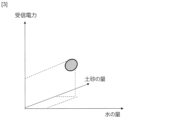
本開示では、図3に示すように、管路82内に存在する土砂、水、さびなど障害物70の種類及び量に応じた電波の伝搬減衰量を予め測定し、演算装置93に備わるデータベースに格納しておく。例えば、障害物70が土砂及び腐食(さび)のときの受信電力、障害物70が腐食(さび)及び水のときの受信電力、障害物70が土砂及び水のときの受信電力、障害物70が土砂及び腐食(さび)及び水のときの受信電力、の4パターンの測定結果を周波数毎に予め格納しておく。演算装置93は、そのデータベースを参照し、手順S11~S14の測定結果を組み合わせ、土砂、水、さび等の管路82内に存在しうる障害物70の種類を推定する。これにより、管路82内に存在しうる障害物70の種類が表示装置95に表示される。
ここで、演算装置93は、障害物70の種類に加え、障害物70の量を推定してもよい。また演算装置93は、管路82内の空洞内において障害物70が占める割合を推定してもよい。また、障害物70の種類や組合せ毎に、管路82内に何%以上存在する場合は非導通である、ということを定義しておいてもよい。そして演算装置93では、信号受信強度を基に、非導通である可能性が何%であるか算出してもよい。
演算装置93は、受信強度および各障害物70の量に応じて、導通可能性が最も高い管路82を判定してもよい。たとえば、土砂・水・さびが同程度存在する場合は、水が存在する管路82を最も導通可能性が高い管と選択してもよい。
なお、手順S12~S14を繰り返す際は、送信装置91及び受信装置92の設置(S11)から再度行ってもよい。例えば、音波又は光など、電波とは異なる信号を使ってもよい。また、送信装置91および受信装置92の配置を入れ替えて再度測定を行ってもよい。また、管路82内を伝搬した伝搬特性に代えて、管路82内で反射された反射特性を測定してもよい。
以上説明したように、本実施形態のシステムは、パイプカメラを用いることなく、受信装置92を用いて取得した複数信号の受信信号の強度の組み合わせから、管路82内の障害物の分類や量の判定を行うことができる。したがって、本実施形態のシステムは、導通点検や管内状態の点検を容易に実施することができる。
(第2の実施形態)
本開示のシステムは、送風装置及び風力計を備えていてもよい。この場合、送信装置91の側から送風装置を用いて空気を管路82に送り込み、受信装置92の側で風力計を用いて風力を測定し、測定結果を演算装置93に出力する。これにより、演算装置93における推定精度を高めることができる。
本開示のシステムは、送風装置及び風力計を備えていてもよい。この場合、送信装置91の側から送風装置を用いて空気を管路82に送り込み、受信装置92の側で風力計を用いて風力を測定し、測定結果を演算装置93に出力する。これにより、演算装置93における推定精度を高めることができる。
本開示のシステムは、送風装置、風力計及び温度計を備えていてもよい。この場合、送信装置91の側から送風装置を用いて温風を管路82に送り込み、受信装置92の側で温度計を用いて温度を測定し、風力計を用いて風力を測定し、これらの測定結果を演算装置93に出力する。これにより、演算装置93における推定精度を高めることができる。
(第3の実施形態)
図4に、本実施形態のシステム構成例を示す。本実施形態のシステムは、第1の実施形態の構成に加え、パイプカメラ94を備える。パイプカメラ94で撮像された画像は演算装置93に送信され、表示装置95に表示される。これにより、本実施形態のシステムは、パイプカメラ94で撮像された管路82内の映像を表示装置95で視認することができる。
図4に、本実施形態のシステム構成例を示す。本実施形態のシステムは、第1の実施形態の構成に加え、パイプカメラ94を備える。パイプカメラ94で撮像された画像は演算装置93に送信され、表示装置95に表示される。これにより、本実施形態のシステムは、パイプカメラ94で撮像された管路82内の映像を表示装置95で視認することができる。
パイプカメラ94を用いた管路82の調査は、例えば、第1の実施形態における手順S11~S14の前に行う。このときに、障害物70の種類が判別できないときに、第1の実施形態における手順S11~S14を実行することで、障害物70の種類を推定することができる。
管路82内が完全にふさがり、手順S13を実行しても演算装置93に受信結果が得られない場合がある。そのような場合に、第1の実施形態における手順S11~S14の後に、パイプカメラ94を用いた管路82の調査を行うことで、管路82をふさいでいる障害物70を特定することができる。
(第4の実施形態)
図5に、本実施形態のシステム構成例を示す。本実施形態のシステムは、パイプカメラ94の先端に、第1の実施形態の送信装置91が搭載されている。この構成を採用することで、第3の実施形態における障害物70の推定と、第3の実施形態における障害物70の撮像と、の両方を同時に行うことができる。
図5に、本実施形態のシステム構成例を示す。本実施形態のシステムは、パイプカメラ94の先端に、第1の実施形態の送信装置91が搭載されている。この構成を採用することで、第3の実施形態における障害物70の推定と、第3の実施形態における障害物70の撮像と、の両方を同時に行うことができる。
本実施形態の構成を採用することで、パイプカメラ94の映像と、受信装置92を用いて取得した複数信号の受信結果の組み合わせから、管路82内の障害物70の分類や量の測定の精度を向上させることができる。
(その他の実施形態)
本発明の演算装置93はコンピュータとプログラムによっても実現でき、プログラムを記録媒体に記録することも、ネットワークを通して提供することも可能である。本開示のプログラムは、本開示に係る演算装置93に備わる各機能をコンピュータに実現させるためのプログラムであり、本開示に係る演算装置93が実行する方法に備わる各手順をコンピュータに実行させるためのプログラムである。
本発明の演算装置93はコンピュータとプログラムによっても実現でき、プログラムを記録媒体に記録することも、ネットワークを通して提供することも可能である。本開示のプログラムは、本開示に係る演算装置93に備わる各機能をコンピュータに実現させるためのプログラムであり、本開示に係る演算装置93が実行する方法に備わる各手順をコンピュータに実行させるためのプログラムである。
70:障害物
81-1、81-2:マンホール
82:管路
91:送信装置
92:受信装置
93:演算装置
94:カメラ
95:表示装置
81-1、81-2:マンホール
82:管路
91:送信装置
92:受信装置
93:演算装置
94:カメラ
95:表示装置
Claims (8)
- 管路内での伝搬特性及び反射特性の少なくともいずれかを、前記管路内に存在する障害物の種類ごとに格納するデータベースと、
前記データベースに基づいて、前記管路内の状態を推定する演算装置と、
を備えるシステム。 - 前記管路内での伝搬特性又は反射特性を測定する測定器を備え、
前記演算装置は、前記測定器での測定結果を前記データベースと照合することで、前記管路内の状態を推定する、
請求項1に記載のシステム。 - 前記データベースは、電波、音波又は光波の少なくともいずれかの伝搬特性又は反射特性を格納する、
請求項1に記載のシステム。 - 前記データベースは、異なる複数の周波数の伝搬特性又は反射特性を格納する、
請求項1に記載のシステム。 - 前記障害物の種類は、土砂、水、及び錆びの少なくともいずれかを含む、
請求項1に記載のシステム。 - 前記管路内を撮像可能なカメラと、
前記カメラで撮像された画像、及び前記演算装置の推定結果を表示する表示装置と、
を備える請求項1に記載のシステム。 - 電波、音波又は光波の少なくともいずれかを送信する送信装置を備え、
前記カメラに前記送信装置が搭載されている、
請求項5に記載のシステム。 - 演算装置が、管路内での伝搬特性及び反射特性の少なくともいずれかを、前記管路内に存在する障害物の種類ごとに格納するデータベースに基づいて、前記管路内の状態を推定する、
方法。
Priority Applications (2)
| Application Number | Priority Date | Filing Date | Title |
|---|---|---|---|
| PCT/JP2023/021363 WO2024252621A1 (ja) | 2023-06-08 | 2023-06-08 | 地中埋設管路の調査方法 |
| JP2025525866A JPWO2024252621A1 (ja) | 2023-06-08 | 2023-06-08 |
Applications Claiming Priority (1)
| Application Number | Priority Date | Filing Date | Title |
|---|---|---|---|
| PCT/JP2023/021363 WO2024252621A1 (ja) | 2023-06-08 | 2023-06-08 | 地中埋設管路の調査方法 |
Publications (1)
| Publication Number | Publication Date |
|---|---|
| WO2024252621A1 true WO2024252621A1 (ja) | 2024-12-12 |
Family
ID=93795609
Family Applications (1)
| Application Number | Title | Priority Date | Filing Date |
|---|---|---|---|
| PCT/JP2023/021363 Pending WO2024252621A1 (ja) | 2023-06-08 | 2023-06-08 | 地中埋設管路の調査方法 |
Country Status (2)
| Country | Link |
|---|---|
| JP (1) | JPWO2024252621A1 (ja) |
| WO (1) | WO2024252621A1 (ja) |
Citations (2)
| Publication number | Priority date | Publication date | Assignee | Title |
|---|---|---|---|---|
| JP2019138862A (ja) * | 2018-02-15 | 2019-08-22 | 三菱電機株式会社 | レーダ信号処理装置 |
| JP2022161052A (ja) * | 2021-04-08 | 2022-10-21 | パナソニックIpマネジメント株式会社 | 超音波流量計 |
-
2023
- 2023-06-08 JP JP2025525866A patent/JPWO2024252621A1/ja active Pending
- 2023-06-08 WO PCT/JP2023/021363 patent/WO2024252621A1/ja active Pending
Patent Citations (2)
| Publication number | Priority date | Publication date | Assignee | Title |
|---|---|---|---|---|
| JP2019138862A (ja) * | 2018-02-15 | 2019-08-22 | 三菱電機株式会社 | レーダ信号処理装置 |
| JP2022161052A (ja) * | 2021-04-08 | 2022-10-21 | パナソニックIpマネジメント株式会社 | 超音波流量計 |
Also Published As
| Publication number | Publication date |
|---|---|
| JPWO2024252621A1 (ja) | 2024-12-12 |
Similar Documents
| Publication | Publication Date | Title |
|---|---|---|
| US10281912B2 (en) | Autonomous inspection system | |
| JP6774451B2 (ja) | 光ファイバケーブル監視方法および光ファイバケーブル監視システム | |
| US20190128848A1 (en) | Sound propagation comparison with automated frequency selection for pipe condition assessment | |
| US10690630B2 (en) | Generation and utilization of pipe-specific sound attenuation | |
| US10565752B2 (en) | Graphical mapping of pipe node location selection | |
| WO2016160267A1 (en) | Determination of pipe wall failure based on minimum pipe wall thickness | |
| Thodi et al. | Arctic pipeline leak detection using fiber optic cable distributed sensing systems | |
| US20160097746A1 (en) | Method for evaluating acoustic sensor data in a fluid carrying network and evaluation unit | |
| JP2017167063A (ja) | 漏洩位置検出方法、及び漏洩位置検出システム | |
| KR101670488B1 (ko) | 관로 삽입형 장치를 이용한 지하시설물 정보 취득 시스템 및 방법 | |
| CN111239842A (zh) | 一种基于分布式光纤传感技术的雨水入侵光缆监测系统及方法 | |
| CN203147289U (zh) | 双Sagnac管道安全监测系统 | |
| CN118500308A (zh) | 水面结冰厚度和水位测量方法、计算机装置和存储介质 | |
| GB2564798A (en) | Leakage site analyzing system, leakage site analyzing method, leakage site analyzing device, and computer-readable recording medium | |
| WO2024252621A1 (ja) | 地中埋設管路の調査方法 | |
| Wu et al. | Pre-existing concrete pipe disconnection detection based on fiber-optic distributed acoustic sensing | |
| CN108731743A (zh) | 基于ofdr分布式光纤的排水管道在线监测系统及方法 | |
| WO2023100312A1 (ja) | 積雪量推定システム及び積雪量推定方法 | |
| JP7380892B2 (ja) | 数モードファイバ試験方法及び数モードファイバ試験装置 | |
| WO2024252617A1 (ja) | 地中埋設管路の導通検査システム | |
| Khan | Empirical Modeling of Acoustic Signal Attenuation in Municipal Sewer Pipes for Condition Monitoring Applications | |
| WO2024252618A1 (ja) | 地中埋設管路の導通検査システム | |
| JP7747174B2 (ja) | 気象推定装置、気象推定システム、気象推定方法、およびプログラム | |
| CN113820395B (zh) | 一种远程粘贴传感器的金属板结构损伤监测系统和方法 | |
| JP3786770B2 (ja) | 配管構造調査方法 |
Legal Events
| Date | Code | Title | Description |
|---|---|---|---|
| 121 | Ep: the epo has been informed by wipo that ep was designated in this application |
Ref document number: 23940719 Country of ref document: EP Kind code of ref document: A1 |
|
| ENP | Entry into the national phase |
Ref document number: 2025525866 Country of ref document: JP Kind code of ref document: A |
|
| NENP | Non-entry into the national phase |
Ref country code: DE |