WO2024257218A1 - Système de transport d'outils, procédé de commande pour système de transport d'outils, et programme de commande pour système de transport d'outils - Google Patents
Système de transport d'outils, procédé de commande pour système de transport d'outils, et programme de commande pour système de transport d'outils Download PDFInfo
- Publication number
- WO2024257218A1 WO2024257218A1 PCT/JP2023/021913 JP2023021913W WO2024257218A1 WO 2024257218 A1 WO2024257218 A1 WO 2024257218A1 JP 2023021913 W JP2023021913 W JP 2023021913W WO 2024257218 A1 WO2024257218 A1 WO 2024257218A1
- Authority
- WO
- WIPO (PCT)
- Prior art keywords
- tool
- tools
- machining
- transport
- machine
- Prior art date
- Legal status (The legal status is an assumption and is not a legal conclusion. Google has not performed a legal analysis and makes no representation as to the accuracy of the status listed.)
- Ceased
Links
Images







Classifications
-
- B—PERFORMING OPERATIONS; TRANSPORTING
- B23—MACHINE TOOLS; METAL-WORKING NOT OTHERWISE PROVIDED FOR
- B23Q—DETAILS, COMPONENTS, OR ACCESSORIES FOR MACHINE TOOLS, e.g. ARRANGEMENTS FOR COPYING OR CONTROLLING; MACHINE TOOLS IN GENERAL CHARACTERISED BY THE CONSTRUCTION OF PARTICULAR DETAILS OR COMPONENTS; COMBINATIONS OR ASSOCIATIONS OF METAL-WORKING MACHINES, NOT DIRECTED TO A PARTICULAR RESULT
- B23Q3/00—Devices holding, supporting, or positioning work or tools, of a kind normally removable from the machine
- B23Q3/155—Arrangements for automatic insertion or removal of tools, e.g. combined with manual handling
-
- B—PERFORMING OPERATIONS; TRANSPORTING
- B23—MACHINE TOOLS; METAL-WORKING NOT OTHERWISE PROVIDED FOR
- B23Q—DETAILS, COMPONENTS, OR ACCESSORIES FOR MACHINE TOOLS, e.g. ARRANGEMENTS FOR COPYING OR CONTROLLING; MACHINE TOOLS IN GENERAL CHARACTERISED BY THE CONSTRUCTION OF PARTICULAR DETAILS OR COMPONENTS; COMBINATIONS OR ASSOCIATIONS OF METAL-WORKING MACHINES, NOT DIRECTED TO A PARTICULAR RESULT
- B23Q41/00—Combinations or associations of metal-working machines not directed to a particular result according to classes B21, B23, or B24
Definitions
- the present disclosure relates to a tool transport system, a control method for a tool transport system, and a control program for a tool transport system.
- Patent Document 1 JP 2022-024522 A discloses a tool transport system that automatically transports tools used in machining to a machine tool.
- the tool transport system has a tool storage unit that can store multiple tools, and transports a specified tool to the machine tool.
- the tool transport system also removes tools that are holding unnecessary tools from the machine tool.
- the tool transport system removes tools from the machine tool to ensure free space in the tool storage area within the machine tool. At this time, if a tool that is scheduled to be used nearby is removed from the machine tool, the tool transport system must immediately load the removed tool back into the machine tool. As a result, the efficiency of tool transport decreases. Therefore, there is a need for technology that can ensure free space in the tool storage area within the machine tool without reducing the efficiency of tool transport.
- Patent Document 1 does not disclose such technology.
- a tool transport system includes a machine tool that uses tools to machine a workpiece, a tool storage unit for storing a plurality of tools, a transport device capable of transporting a specified tool from among a tool in the machine tool and a tool in the tool storage unit to a specified destination from among the machine tool and the tool storage unit, and a control unit for controlling the transport device.
- the control unit executes a process of identifying a second machining operation to be performed after a first machining operation based on the occurrence of a predetermined event, and a process of transporting a tool other than the tool to be used in the first machining operation, which is to be used in the second machining operation, from the machine tool to the tool storage unit.
- the predetermined event includes an interrupt event that executes the first processing in priority over other processing.
- control unit after executing the unloading process, the control unit further executes a process of loading the tool to be used in the first machining from the tool storage unit into the machine tool.
- the second processing includes the processing scheduled to be performed last among the processing scheduled in the processing schedule.
- control unit if there is an unusable tool in the machine tool, the control unit further executes a process to transport the unusable tool from the machine tool to the tool storage unit before executing the transport process.
- a control method for a tool transport system includes a machine tool, a tool storage unit for storing a plurality of tools, and a transport device capable of transporting a specified tool from among a tool in the machine tool and a tool in the tool storage unit to a specified destination between the machine tool and the tool storage unit.
- the control method includes a step of identifying a second machining operation to be performed after a first machining operation based on the occurrence of a predetermined event, and a step of transporting a tool other than the tool to be used in the first machining operation, the tool to be used in the second machining operation, from the machine tool to the tool storage unit.
- a control program for a tool transport system includes a machine tool, a tool storage unit for storing a plurality of tools, and a transport device capable of transporting a specified tool from among a tool in the machine tool and a tool in the tool storage unit to a specified destination between the machine tool and the tool storage unit.
- the control program causes the tool transport system to execute the steps of: identifying a second machining operation to be performed after a first machining operation based on the occurrence of a predetermined event; and transporting a tool other than the tool to be used in the first machining operation from the machine tool to the tool storage unit, the tool being the tool to be used in the second machining operation.
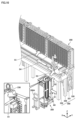
- FIG. 1 is a diagram showing the appearance of a tool transport system.
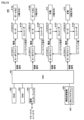
- FIG. 2 is a diagram illustrating a configuration example of a drive mechanism of the tool transport system.
- FIG. 13 is a diagram illustrating a method for determining a tool to be removed from a machine tool.
- FIG. 2 is a diagram illustrating an example of a functional configuration of a tool transport system.
- FIG. 11 is a diagram showing an example of tool information.
- 11A and 11B are diagrams illustrating an example of an input to a transport control unit and an output of the transport control unit in response to the input.
- 13 is a diagram illustrating a method for determining a tool to be removed;
- FIG. 13 is a diagram illustrating a method for determining a tool to be carried in.
- FIG. 10 is a diagram illustrating an outline of a transport order of tools to be carried out and tools to be carried in;
- FIG. 11 is a diagram illustrating a flow of a process of carrying a tool from a work station to a tool storage section.
- FIG. 10 is a diagram illustrating a flow of a process for carrying a tool from a tool storage unit to a machine tool.
- FIG. 1 is a diagram illustrating a flow of a process for carrying out a tool from a machine tool to a work station.
- FIG. FIG. 2 illustrates an example of a hardware configuration of a management apparatus. A diagram showing an example of the hardware configuration of a PLC (Programmable Logic Controller).
- FIG. 2 is a diagram illustrating an example of a hardware configuration of a machine tool.
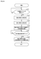
- FIG. 11 is a flowchart showing a tool transport process when a tool transport event occurs.
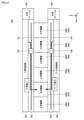
- FIG. 13 is a diagram showing a tool transport system according to a modified example.
- Fig. 1 is a diagram showing the external appearance of the tool conveyance system 10.
- the work station 200 is a place where a worker works on tools. For example, the worker works at the work station 200 to set up tools or retrieve tools.
- the work station 200 includes an operation terminal 200A.
- the operation terminal 200A accepts various operations for the tool transport system 10.
- the tool storage section 250 can store multiple tools.
- the tool storage section 250 functions as a temporary storage area for tools.
- transport the transport mode in which the transport device 300 transports a tool from the work station 200 to the tool storage unit 250 or the machine tool 400, or the transport mode in which the transport device 300 transports a tool from the tool storage unit 250 to the machine tool 400, is also referred to as "transport.”
- transport device as used in this specification is a concept that includes various devices that have the function of transporting tools.
- a 4- to 7-axis driven articulated robot will be described as an example of the transport device 300, but the transport device 300 is not limited to an articulated robot.
- the transport device 300 may be a 2- to 3-axis driven Cartesian robot (autoloader).
- the transport device 300 may be a self-propelled robot.
- the transport device 300 includes an arm robot 330, a rail 331, and a cart 332.
- the arm robot 330 is fixed onto the cart 332.
- the cart 332 is configured to be movable on the rail 331.
- the tool storage unit 250 and the machine tool 400 are arranged parallel to each other along the rail 331, sandwiching the rail 331.
- the machine tool 400 is one of the destinations to which tools are transported by the transport device 300.
- six machine tools 400A-400F are shown as the machine tools 400, but the number of machine tools 400 constituting the tool transport system 10 may be one or more.
- the machine tools 400 machine a workpiece using a specified tool according to a pre-designed machining program.
- the term "machine tool” as used in this specification is a concept that includes various devices that have the function of machining a workpiece.
- the machine tool 400 may be a horizontal machining center or a vertical machining center.
- the machine tool 400 may be a lathe, an additional processing machine, or any other cutting machine or grinding machine.
- the tool transport system 10 includes the work station 200, but the tool transport system 10 does not have to include the work station 200.
- FIG. 2 is a diagram showing an example of the configuration of the driving mechanisms in the tool conveyance system 10.
- the tool transport system 10 includes a control unit 50, remote I/O (Input/Output) units 71-73, a work station 200, a transport device 300, and a machine tool 400.
- control unit 50 remote I/O (Input/Output) units 71-73
- work station 200 work station 200
- transport device 300 transport device 300
- machine tool 400 machine tool 400
- the management device 100 is a main computer that manages the tool transport system 10.
- the management device 100 may be composed of one computer or multiple computers.
- the PLC 150 is configured to be able to communicate with various industrial devices for automating the machining process, and controls the industrial devices.
- the operation terminal 200A is a terminal for receiving various operations related to the loading and unloading of tools.
- the management device 100, PLC 150, and operation terminal 200A may be connected to a network NW1.
- the management device 100, PLC 150, and operation terminal 200A may be connected for communication via a wired or wireless connection.
- EtherNET registered trademark
- the management device 100 and operation terminal 200A send control commands to the PLC 150 via the network NW1.
- the control commands specify the tool to be transported, the destination of the tool, start/stop transport of the tool, etc.
- the remote I/O units 71-73 and the PLC 150 are connected to the network NW2.
- NW2 it is preferable to use a field network that performs periodic communication and guarantees the arrival time of data.
- field networks that perform such periodic communication include EtherCAT (registered trademark), EtherNet/IP (registered trademark), CC-Link (registered trademark), and CompoNet (registered trademark).
- the work station 200 includes one or more motor drivers 234 and one or more motors 235.
- motor drivers 234A, 234B and two motors 235A, 235B are shown.
- a remote I/O unit 71 is installed in or near the work station 200.
- the remote I/O unit 71 mediates data exchange between various drive units (e.g., motor driver 234) in the work station 200 and the PLC 150.
- the motor driver 234 receives control commands from the PLC 150 via the remote I/O unit 71 at regular intervals, and controls the drive of the motor 235 in accordance with the control commands.
- Motor 235A controls the driving of magazine M1 (see FIG. 10) in work station 200, which will be described later.
- Motor 235B controls the driving of ATC (Automatic Train Control) 238 (see FIG. 10) in work station 200, which will be described later.
- ATC Automatic Train Control
- Motor driver 234 may be, for example, a driver for a servo motor or a driver for a stepping motor.
- Motor 235 may be a servo motor or a stepping motor.
- the conveying device 300 includes one or more motor drivers 334 and one or more motors 335.
- motor drivers 334A and 334B and two motors 335A and 335B are shown.
- a remote I/O unit 72 is installed inside or near the conveying device 300.
- the remote I/O unit 72 mediates data exchange between various drive units (e.g., motor driver 334) inside the conveying device 300 and the PLC 150.
- the motor driver 334 receives control commands from the PLC 150 via the remote I/O unit 72 at regular intervals, and controls the drive of the motor 335 in accordance with the control commands.
- Motor 335A controls the driving of the above-mentioned cart 332 (see FIG. 1).
- Motor 335B controls the driving of arm robot 330 (see FIG. 1).
- Motors 335B are provided according to the number of joints of arm robot 330.
- Motor driver 334 may be, for example, a driver for a servo motor or a driver for a stepping motor.
- Motor 335 may be a servo motor or a stepping motor.
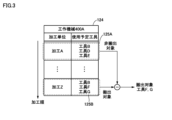
- Fig. 3 is a diagram showing an outline of a method for determining a tool to be removed from the machine tool 400.
- the transport device 300 transports the tools out of the machine tool 400.
- the tool transport system 10 determines the tools to be transported out of the machine tool 400 based on the machining schedule 124.
- the machining schedule 124 specifies the order of each machining operation in each of the machine tools 400 and the tools used in each machining operation.
- the machining schedule 124 for the machine tool 400A is shown.
- the order of each machining operation in the machine tool 400A may be specified by the machining start time or by the order of the data.
- the tools planned to be used specified in the machining schedule 124 indicate the tools required for each machining operation.
- the tools planned to be used can be associated with various machining units. As one example, the tools planned to be used are associated with each machining program. As another example, the tools planned to be used are associated with each pallet. A pallet is a base for fixing the workpiece to be machined. As yet another example, the tools planned to be used are associated with each workpiece to be machined.
- the control unit 50 of the tool transport system 10 determines the tool to be removed from the machine tool 400 based on the occurrence of a predetermined event (hereinafter also referred to as a "tool removal event").
- the tool removal event can occur at various times. As an example, such times include the timing when the machining schedule 124 is updated, the timing when an interrupt process occurs that prioritizes one machining process over another, and the timing when machining in each machining unit is completed.
- the control unit 50 identifies the machining 125A (first machining) that is scheduled to be executed immediately after the occurrence of a tool removal event.
- the machining 125A is, for example, the machining unit that is scheduled to be executed next after the current time. Note that the machining 125A may be the machining unit that is immediately next in the machining order, or may be a predetermined number of machining units that are scheduled to be executed consecutively from the machining.
- the control unit 50 then identifies processing 125B (second processing) that is scheduled to be executed after processing 125A.
- Processing 125B is, for example, the last processing unit scheduled to be executed among the processing units scheduled in the processing schedule 124. Note that processing 125B may be a single processing unit that is the last in the processing order, or may be one of a predetermined number of processing units that are later in the processing order.
- the control unit 50 determines the tools other than the tools to be used in the machining 125A and to be used in the machining 125B as the tools to be transferred from the machine tool 400 to the tool storage unit 250.
- the control unit 50 determines the "tools B, D, E” to be used in the machining 125A as the tools not to be transferred, and the "tools B, F, G” to be used in the machining 125B as the tools to be temporarily transferred.
- the control unit 50 removes the "tools B, D, E” that are not to be transferred from the "tools B, F, G” that are the tools to be temporarily transferred, and finally determines the remaining "tools F, G” as the tools to be transferred. This allows the tool transfer system 10 to secure a space in the tool storage area in the machine tool 400 while avoiding the transfer of tools that are to be used soon. As a result, the number of times the tools are transferred is reduced, and the efficiency of the tool transfer is improved.
- the processing after processing 125A is not limited to this.
- the processing scheduled next after processing 125A may be selected as the processing after processing 125A.
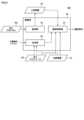
- Fig. 4 is a diagram showing an example of the functional configuration of the tool transport system 10.
- the tool transport system 10 includes, as its functional components, a monitoring unit 52, a transport control unit 54, and a determination unit 56. Below, these components will be described in order.
- each functional configuration may be implemented in any device within the tool transport system 10. Some or all of the functional configurations shown in FIG. 4 may be implemented in the above-mentioned management device 100 (see FIG. 2), the above-mentioned PLC 150 (see FIG. 2), the above-mentioned operation terminal 200A (see FIG. 1), or the above-mentioned CNC 401 (see FIG. 2).
- Fig. 5 is a diagram showing tool information 174 as an example.
- the monitoring unit 52 monitors the status of each tool in the tool transport system 10 and writes the status to the tool information 174.
- the tool information 174 associates the identification information of the tool, the available amount of the tool, the current amount of the tool used, the remaining life of the tool, and the status of the tool.
- the tool identification information defined in the tool information 174 is information for uniquely identifying a tool.
- the identification information is assigned in advance to each tool.
- the identification information may be indicated by a tool number such as an ID (Identification) or may be indicated by a tool name.
- Monitoring unit 52 monitors machining program 422 of machine tool 400, and counts the usage of each tool in machine tool 400 from when it was new to the present.
- “Amount” here is a concept that includes time, distance, and number of times.
- “Usage amount of a tool” includes, for example, the total time that the tool has been used in machining from new to the present, the total distance traveled during machining from new to the present, and the total number of times that the tool has been used in machining from new to the present.
- the usable amount specified in the tool information 174 indicates the maximum usable amount of the tool from when it is new until the end of its life.
- the usable amount of each tool is determined in advance by the tool manufacturer, etc.
- the current usage amount specified in the tool information 174 indicates the amount of usage of the tool from when it was new to the present.
- the current usage amount is updated by the monitoring unit 52.
- the remaining life specified in the tool information 174 indicates the remaining usage of the tool from the present until the end of the tool's life. Typically, the remaining life corresponds to the result of subtracting the current usage of the tool from the maximum usable amount of the tool.
- the monitoring unit 52 updates the current usage amount specified in the tool information 174, it also updates the remaining life.
- tools that are in a usable state are shown as “normal” or “life warning.”
- “Life warning” indicates that the tool is nearing the end of its life.
- the monitoring unit 52 changes the tool's state in the storage information 175 from “normal” to "life warning.”
- unusable tools are indicated as "out of service life” or "damaged.”
- An “unusable tool” refers to a tool that is not recommended for use in machining a workpiece.
- an "unusable tool” refers to a tool other than a “usable tool.”
- tools that are unusable include tools that have reached the end of their life due to wear and the like, and tools that have been damaged.
- Types of damage to tools include, for example, deformation of the tool due to application of excessive force, chipping of the tool blade, and breakage of the tool.
- the monitoring unit 52 changes the tool's status in the storage information 175 from "lifespan warning" to "lifespan expired.”
- Fig. 6 is a diagram showing an example of an input to the transport control unit 54 and an output of the transport control unit 54 in response to the input.
- the transport control unit 54 receives, for example, the processing schedule 124 and storage information 175 as input, and outputs a tool transport command to the transport device 300.
- the storage location defined in the storage information 175 is information for uniquely identifying the location of the tool within the tool transport system 10.
- the storage location indicates the storage position of the tool within the work station 200, the storage position of the tool within the tool storage section 250, the storage position of the tool within the transport device 300, or the storage position of the tool within the machine tool 400.
- the identification information of the tool holder defined in the storage information 175 is information for uniquely identifying the tool holder.
- the identification information is assigned in advance to each tool holder.
- the identification information may be indicated by a tool holder number such as an ID, or may be indicated by the tool holder name.
- the tool identification information defined in the storage information 175 is information for uniquely identifying a tool.
- the identification information is assigned in advance to each tool.
- the identification information may be indicated by a tool number such as an ID, or may be indicated by the tool name.
- the identification information corresponds to the tool identification information defined in the above-mentioned tool information 174 (see FIG. 5).
- the transport control unit 54 refers to the machining schedule 124 and identifies the tool to be used on the machine tool 400 before machining of the workpiece begins. Next, the transport control unit 54 refers to the storage information 175, and if the tool to be used is not present in the target machine tool 400, controls the transport device 300 to transport the tool to be used from the work station 200 or the tool storage unit 250 to the target machine tool 400.
- the transport control unit 54 also causes the transport device 300 to transport the tools in the machine tool 400 out.
- the transport control unit 54 controls the transport device 300 to transport the tools to be transported out, determined by the determination unit 56 described below, out of the machine tool 400. Thereafter, the transport control unit 54 controls the transport device 300 to transport the tools to be transported in, determined by the determination unit 56 described below, from the tool storage unit 250 into the machine tool 400.
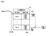
- Fig. 7 is a diagram showing an outline of a method for determining tools to be removed.
- the determination unit 56 determines the tool to be removed from the machine tool 400A based on the occurrence of a tool removal event in the machine tool 400A.
- the tool removal event occurs due to an interrupt operation that prioritizes the machining of one workpiece over the machining of another workpiece.
- the interrupt operation may be accepted, for example, by the above-mentioned management device 100 or by the work station 200.
- an interruption occurs for processing 125A.
- the decision unit 56 updates the processing schedule 124 so that processing 125A is executed with the highest priority.
- the determination unit 56 identifies the processing 125B that is scheduled to be performed after the processing 125A.
- the last processing 125B scheduled in the processing schedule 124 is identified.
- the determination unit 56 determines tools other than the tools to be used in machining 125A and to be used in machining 125B as tools to be transported from the machine tool 400A to the tool storage unit 250.
- the determination unit 56 sets “tools B, D, E” to be used in machining 125A as tools not to be transported, and "tools B, F, G” to be used in machining 125B as tools to be transported.
- the determination unit 56 removes "tools B, D, E” that are not to be transported from “tools B, F, G” to be transported, and determines the remaining "tools F, G" as tools to be transported.
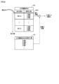
- Figure 8 is a diagram showing an outline of the method for determining the tool to be brought in.
- the determination unit 56 determines a tool other than the tools held by the machine tool 400A and to be used in the machining 125A as a tool to be transferred from the tool storage unit 250 to the machine tool 400.
- the tools held by the machine tool 400A are identified, for example, based on the storage information 175 described above.
- the machine tool 400A holds “tools A, B, C, F.” Therefore, the determination unit 56 sets “tools A, B, C, F” held by the machine tool 400A as non-import targets, and sets “tools B, D, E” used in the most recent machining 125A as provisional targets for import.
- the determination unit 56 removes "tools A, B, C, F” that are not targets for import from "tools B, D, E” that are provisional targets for import, and finally determines the remaining "tools D, E” as targets for import.
- the determination unit 56 transfers the unusable tool from the machine tool 400A to the tool storage unit 250 before executing the process of transferring the tool to be transferred.
- the determination unit 56 prioritizes the unusable tool as a tool to be transferred over the tool to be transferred that has been determined based on the machining order.
- the determination unit 56 determines the unusable tool as the tool to be removed rather than the usable tool, thereby preventing the tool storage space in the machine tool 400 from being wasted. Whether or not there is an unusable tool in the machine tool 400 is determined based on the above-mentioned tool information 174 (see FIG. 5) and the above-mentioned storage information 175 (see FIG. 6).
- the determination unit 56 determines the tools to be removed so that the number of available tool storage spaces in the machine tool 400A is greater than the number of tools to be brought in. Typically, the determination unit 56 determines the tools to be removed in order of the tools that are scheduled to be used later, based on the machining schedule 124.
- the tools to be removed as determined by the determination unit 56 and the tools to be brought in as determined by the determination unit 56 are output to the transport control unit 54 described above.
- FIG. 9 is a diagram showing an outline of the order of transport of tools to be removed and tools to be brought in.
- the transport control unit 54 controls the transport device 300 to transport the tools to be removed, determined by the determination unit 56, from the machine tool 400A to the tool storage unit 250.
- the transport control unit 54 determines that the removal process in step S51 is complete.
- the transport control unit 54 controls the transport device 300 to transport the tools to be brought in, determined by the determination unit 56, from the tool storage unit 250 to the machine tool 400. This allows the tool transport system 10 to preferentially transport tools to be used in the most recent machining to the machine tool 400A, thereby improving machining efficiency.
- Fig. 10 is a diagram showing a schematic flow of a process of carrying a tool from the work station 200 to the tool storage unit 250.
- step S1 the worker sets the tool holder H1 to be loaded into the magazine M1 in the work station 200.
- the tool to be loaded is attached to the tool holder H1.
- the number of tool holders that can be stored in the work station 200 is less than the number of tool holders that can be stored in the tool storage section 250.
- a barcode or QR code (registered trademark) reader (not shown) is provided near the position where the worker sets the tool holder H1 in the magazine M1.
- the reader reads the barcode or QR code attached to the tool holder H1. This allows the identifier of the tool holder H1 to be loaded to be read.
- the worker has finished setting the tool holder H1, he or she performs a completion operation on the operation terminal 200A.
- step S2 the control unit 50 controls the motor 235A (see FIG. 2) to drive the magazine M1 in the work station 200.
- the control unit 50 moves the tool holder H1 to be loaded to a predetermined tool exchange position.
- the ATC 238 is provided near the tool exchange position. The ATC 238 removes the tool holder H1 at the tool exchange position from the magazine M1 and rotates it half a turn.
- step S3 the arm robot 330 removes the tool holder H1 from the ATC 238 and places the tool holder H1 in the temporary storage area 336 on the cart 332. If there are other tool holders to be brought in, steps S1 to S3 are repeated as long as the number of tool holders does not exceed the maximum number that can be stored in the temporary storage area 336.
- step S4 the control unit 50 controls the motor 335A to drive the cart 332.
- the control unit 50 moves the cart 332 to the instructed tool loading position.
- the tool loading position is determined, for example, based on the above-mentioned storage information 175 (see FIG. 6).
- the control unit 50 determines the storage destination of the tool holder H1 by referring to the empty storage locations specified in the storage information 175. If there are multiple empty storage locations, the control unit 50 may determine one storage location randomly selected from the multiple empty storage locations as the storage destination, or may determine one of the multiple empty storage locations that is closest to the conveying device 300 as the storage destination.
- step S5 the arm robot 330 removes the tool holder H1 to be carried in from the temporary storage area 336 and stores the tool holder H1 in the determined storage location.
- the control unit 50 updates the storage information 175 by associating the identifier of the tool holder H1 with the corresponding storage location.
- control unit 50 repeats steps S4 and S5 until there are no more tool holders remaining in the temporary storage area 336.
- Fig. 11 is a diagram showing a schematic flow of the tool carrying-in process from the tool storage unit 250 to the machine tool 400.
- the control unit 50 identifies the tool to be brought in and the machine tool 400 to which it is to be transported according to the above-mentioned machining schedule 124. As a result, it is assumed that tool holder H2 is identified as the tool to be brought in. In this case, the control unit 50 identifies the storage location of tool holder H2 from the above-mentioned storage information 175 (see FIG. 6). Thereafter, the control unit 50 drives the cart 332 by controlling the motor 335A (see FIG. 2) to move the cart 332 in front of the storage location of tool holder H2.
- step S11 the arm robot 330 removes the tool holder H2 to be transported from the tool storage section 250 and places the tool holder H2 in the temporary storage area 336 on the cart 332.
- step S12 the control unit 50 controls the motor 335A to drive the carriage 332 to the position of the destination machine tool 400.
- step S13 the arm robot 330 delivers the tool holder H2 to the ATC 438 provided in the destination machine tool 400.
- the ATC 438 then sets the tool holder H2 in a magazine inside the machine tool 400.
- Fig. 12 is a diagram showing a schematic flow of the process of carrying out the tool from the machine tool 400 to the work station 200.
- the control unit 50 receives a tool holder recovery instruction. Based on this, the control unit 50 identifies a tool holder to be recovered from among the tool holders stored in the machine tool 400. As a result, it is assumed that the tool holder H3 is identified as the tool holder to be recovered.
- the control unit 50 identifies the storage destination of the tool holder H3 by referring to the above-mentioned storage information 175 (see FIG. 6). Thereafter, the control unit 50 drives the cart 332 by controlling the above-mentioned motor 335A (see FIG. 2) and moves the cart 332 in front of the machine tool 400 storing the tool holder H3.
- the arm robot 330 takes out the tool holder H3 from the machine tool 400 and places the tool holder H3 in the temporary storage area 336 on the cart 332.
- the control unit 50 also deletes the identifier of the tool holder H3 from the storage information 175 and rewrites the storage source of the tool holder H3 to an empty state.
- step S21 the control unit 50 drives the carriage 332 by controlling the above-mentioned motor 335A, and moves the carriage 332 from in front of the machine tool 400 to in front of the work station 200.
- step S22 the arm robot 330 removes the tool holder H3 to be removed from the temporary storage area 336, and attaches the tool holder H3 to the ATC 238 (see FIG. 10) provided in the work station 200.
- the ATC 238 then attaches the tool holder H3 to the magazine M1 of the work station 200.
- step S23 the control unit 50 controls the motor 235A to drive the magazine M1 and move the tool holder H3 to be removed to the front of the exit. After that, the worker removes the tool holder H3 to be removed from the exit.
- Fig. 13 is a diagram showing an example of the hardware configuration of the management device 100.
- the management device 100 includes a control circuit 101, a ROM (Read Only Memory) 102, a RAM (Random Access Memory) 103, a communication interface 104, a display interface 105, an input interface 107, and an auxiliary storage device 120. These components are connected to a bus 110.
- the control circuit 101 is composed of at least one integrated circuit.
- the integrated circuit may be composed of, for example, at least one CPU (Central Processing Unit), at least one GPU (Graphics Processing Unit), at least one ASIC (Application Specific Integrated Circuit), at least one FPGA (Field Programmable Gate Array), or a combination thereof.
- CPU Central Processing Unit
- GPU Graphics Processing Unit
- ASIC Application Specific Integrated Circuit
- FPGA Field Programmable Gate Array
- the control circuit 101 controls the operation of the management device 100 by executing various programs such as a control program 122 and an operating system. Based on receiving an execution command for the control program 122, the control circuit 101 reads the control program 122 from the auxiliary storage device 120 or ROM 102 to the RAM 103.
- the RAM 103 functions as a working memory and temporarily stores various data required for the execution of the control program 122.
- a LAN Local Area Network
- an antenna etc. are connected to the communication interface 104.
- the management device 100 is connected to the network NW1 via the communication interface 104. This allows the management device 100 to exchange data with external devices connected to the network NW1.
- the external devices include, for example, a PLC 150 and a server (not shown).
- the display interface 105 is connected to the display 106.
- the display interface 105 sends an image signal for displaying an image to the display 106 in accordance with instructions from the control circuit 101 or the like.
- the display 106 displays, for example, an operation screen for receiving interrupt instructions for processing.
- the display 106 is, for example, a liquid crystal display, an organic EL (Electro Luminescence) display, or other display device.
- the display 106 may be configured integrally with the management device 100, or may be configured separately from the management device 100.
- An input device 108 is connected to the input interface 107.
- the input device 108 is, for example, a mouse, a keyboard, a touch panel, or any other device capable of accepting user operations.
- the input device 108 may be configured integrally with the management device 100, or may be configured separately from the management device 100.
- the auxiliary storage device 120 is a storage medium such as a hard disk or flash memory.
- the auxiliary storage device 120 stores the control program 122 and the above-mentioned machining schedule 124.
- the storage location of the control program 122 and the machining schedule 124 is not limited to the auxiliary storage device 120, and may be stored in a memory area of the control circuit 101 (e.g., cache memory), the ROM 102, the RAM 103, or another device (e.g., a server, the PLC 150, or the operation terminal 200A), etc.
- the control program 122 is a program for realizing some or all of the functional configuration shown in FIG. 4 above.
- the control program 122 may be provided not as a standalone program, but incorporated as part of an arbitrary program. In this case, the transport control process by the control program 122 is realized in cooperation with the arbitrary program. Even if the program does not include some of these modules, it does not deviate from the spirit of the control program 122 according to this embodiment.
- some or all of the functions provided by the control program 122 may be realized by dedicated hardware.
- the management device 100 may be configured in the form of a so-called cloud service in which at least one server executes part of the processing of the control program 122.
- FIG. 14 is a diagram showing an example of a hardware configuration of the PLC 150.
- PLC 150 includes a control circuit 151, a ROM (Read Only Memory) 152, a RAM (Random Access Memory) 153, communication interfaces 154 and 155, and an auxiliary storage device 170. These components are connected to a bus 160.
- ROM Read Only Memory
- RAM Random Access Memory
- the control circuit 151 is composed of at least one integrated circuit.
- the integrated circuit is composed of, for example, at least one CPU, at least one MPU (Micro Processing Unit), at least one ASIC, at least one FPGA, or a combination thereof.
- the control circuit 151 controls the operation of the conveying device 300, the machine tool 400, etc. by executing various programs such as the control program 172. Based on receiving an execution command for the control program 172, the control circuit 151 reads the control program 172 from the auxiliary storage device 170 to the ROM 152.
- the RAM 153 functions as a working memory, and temporarily stores various data required for the execution of the control program 172.
- a LAN, an antenna, etc. are connected to the communication interface 154.
- the PLC 150 is connected to the network NW1 via the communication interface 154. This allows the PLC 150 to exchange data with external devices connected to the network NW1.
- external devices include, for example, the management device 100 and a server (not shown).
- the communication interface 155 is an interface for connecting to the network NW2, which is a field network.
- the PLC 150 exchanges data with external devices connected to the network NW2 via the communication interface 155.
- external devices include, for example, the above-mentioned remote I/O units 71 to 73.
- the auxiliary storage device 170 is a storage medium such as a hard disk or flash memory.
- the auxiliary storage device 170 stores the control program 172, the above-mentioned tool information 174, and the above-mentioned storage information 175.
- the storage location of these is not limited to the auxiliary storage device 170, and may be stored in the memory area of the control circuit 151 (e.g., a cache area), the ROM 152, the RAM 153, an external device (e.g., a server), etc.
- the control program 172 is a program for realizing all or part of the functional configuration shown in FIG. 4 above.
- the control program 172 may be provided not as a standalone program, but incorporated as part of an arbitrary program. In this case, the control processing according to this embodiment is realized in cooperation with the arbitrary program. Even if the program does not include some of these modules, it does not deviate from the spirit of the control program 172 according to this embodiment.
- all or part of the functions provided by the control program 172 may be realized by dedicated hardware.
- the PLC 150 may be configured in the form of a so-called cloud service in which at least one server executes part of the processing of the control program 172.
- FIG. 15 is a diagram showing an example of a hardware configuration of machine tool 400.
- the machine tool 400 includes a CNC 401, a ROM 402, a RAM 403, a communication interface 404, motor drivers 411A-411D, motors 412A-412D, encoders 413A-413D, ball screws 414A and 414B, and a spindle 415 for attaching a tool. These devices are connected via a bus (not shown).
- CNC401 is composed of at least one integrated circuit.
- the integrated circuit is composed of, for example, at least one CPU, at least one MPU, at least one ASIC, at least one FPGA, or a combination thereof.
- the CNC 401 controls the operation of the machine tool 400 by executing various programs such as a machining program 422. Upon receiving an execution command for the machining program 422, the CNC 401 reads the machining program 422 from the auxiliary storage device 420 to the ROM 402.
- the RAM 403 functions as a working memory and temporarily stores various data required for the execution of the machining program 422.
- the communication interface 404 is an interface for realizing communication with the PLC 151 via the remote I/O unit 73.
- the CNC 401 exchanges data with the PLC 151 via the communication interface 404.
- the CNC 401 controls the motor drivers 411A to 411D according to the machining program 422.
- Each of the motor drivers 411A to 411D may be, for example, a driver for a servo motor or a driver for a stepping motor.
- the CNC 401 sequentially outputs a control signal including a target rotation speed (or target position) to the motor driver 411A.
- the motor driver 411A calculates the actual rotation speed (or actual position) of the motor 412A from the feedback signal of the encoder 413A, and outputs a current to the motor 412A so that the difference between the actual rotation speed and the target rotation speed becomes small.
- the motor driver 411A sequentially receives feedback of the rotation speed of the motor 412A and brings the rotation speed of the motor 412A closer to the target rotation speed.
- the motor driver 411A moves the workpiece setting table connected to the ball screw 414A to any position in the X-axis direction.
- the CNC 401 sequentially outputs a control signal including a target rotation speed (or target position) to the motor driver 411B.
- the motor driver 411B calculates the actual rotation speed (or actual position) of the motor 412B from the feedback signal of the encoder 413B, and outputs a current to the motor 412B so that the difference between the actual rotation speed and the target rotation speed becomes small.
- the motor driver 411B sequentially receives feedback of the rotation speed of the motor 412B and brings the rotation speed of the motor 412B closer to the target rotation speed.
- the motor driver 411B moves the workpiece setting table connected to the ball screw 414B to an arbitrary position in the Y-axis direction.
- the CNC 401 sequentially outputs a control signal including a target rotation speed (or target position) to the motor driver 411C.
- the motor driver 411C calculates the actual rotation speed (or actual position) of the motor 412C from the feedback signal of the encoder 413C, and outputs a current to the motor 412C so that the difference between the actual rotation speed and the target rotation speed becomes small.
- the motor driver 411C sequentially receives feedback of the rotation speed of the motor 412C and brings the rotation speed of the motor 412C closer to the target rotation speed. In this way, the motor driver 411C moves the spindle 415 to an arbitrary position in the Z-axis direction.
- the CNC 401 sequentially outputs a control signal including a target rotation speed (or target position) to the motor driver 411D.
- the motor driver 411D calculates the actual rotation speed (or actual position) of the motor 412D from the feedback signal of the encoder 413D, and outputs a current to the motor 412D so as to reduce the difference between the actual rotation speed and the target rotation speed.
- the motor driver 411D sequentially receives feedback of the rotation speed of the motor 412D and brings the rotation speed of the motor 412D closer to the target rotation speed. In this way, the motor driver 411D controls the rotation speed of the spindle 415.
- the auxiliary storage device 420 is a storage medium such as a hard disk or a flash memory.
- the auxiliary storage device 420 stores the machining program 422 and the like.
- the storage location of the machining program 422 is not limited to the auxiliary storage device 420, and may be stored in the memory area of the CNC 401 (e.g., a cache area), the ROM 402, the RAM 403, an external device (e.g., a server), etc.
- Fig. 16 is a diagram showing a flowchart relating to a tool transport process when a tool transport event occurs.
- the process shown in FIG. 16 is realized by the control unit 50 executing a control program. In other aspects, some or all of the process may be performed by circuit elements or other hardware.
- step S110 the control unit 50 determines whether or not a tool removal event has occurred. If the control unit 50 determines that a tool removal event has occurred (YES in step S110), it switches control to step S112. If not (NO in step S110), the control unit 50 returns control to step S110.
- step S112 the control unit 50 functions as the determination unit 56 (see FIG. 4) described above, and determines the tool to be transferred from the machine tool 400 to the work station 200 or the tool storage unit 250.
- the method for determining the tool to be transferred is as described above, so the description will not be repeated.
- step S114 the control unit 50 functions as the determination unit 56 described above, and determines the tool to be transferred from the work station 200 or the tool storage unit 250 to the machine tool 400.
- the method for determining the tool to be transferred is as described above, so the description will not be repeated.
- step S116 the control unit 50 functions as the above-mentioned transport control unit 54 (see FIG. 4) and controls the transport device 300 to transport the tool to be removed, determined in step S112, from the machine tool 400 to the tool storage unit 250.
- step S120 the control unit 50 determines whether the unloading process in step S116 has ended. If the control unit 50 determines that the unloading process in step S116 has ended (YES in step S120), it switches control to step S122. If not (NO in step S120), the control unit 50 returns control to step S120.
- control unit 50 functions as the above-mentioned transport control unit 54, and controls the transport device 300 to transport the tool to be loaded determined in step S114 from the work station 200 or the tool storage unit 250 to the machine tool 400.
- Fig. 17 is a diagram showing a tool transport system 10A according to the modified example.
- the tool transport system 10A according to this modified example differs from the above-described tool transport system 10 in that it not only has the function of transporting tools to the machine tool 400, but also the function of transporting workpieces to the machine tool 400.
- the tool transport system 10A includes a work station 200, a tool storage unit 250, a transport device 300, a machine tool 400, a work station 500, a work storage unit 550, and a transport device 600.
- the work station 200, the tool storage unit 250, the transport device 300, and the machine tool 400 have been described above, and therefore their description will not be repeated.
- the work station 500 is a place where a worker works on a workpiece. For example, at the work station 500, the worker sets up the workpiece to be processed or collects the workpiece that has already been processed.
- the work storage section 550 can store multiple workpieces.
- the work storage section 550 functions as a temporary storage area for the workpieces.
- the transport device 600 transports a specified workpiece from among the workpiece in the machine tool 400, the workpiece in the work station 500, and the workpiece in the work storage unit 550 to a specified destination from among the machine tool 400, the work station 500, and the work storage unit 550.
- the transport device 600 includes an arm robot 630 and a rail 631.
- the arm robot 630 is fixed onto a cart (not shown).
- the cart is configured to be movable on the rail 631.
- the machine tool 400 and the work storage unit 550 are arranged on either side of the rail 631 and parallel to the rail 631.
- 10 Tool transport system 10A Tool transport system, 50 Control unit, 52 Monitoring unit, 54 Transport control unit, 56 Decision unit, 71 Remote I/O unit, 72 Remote I/O unit, 73 Remote I/O unit, 100 Management device, 101 Control circuit, 102 ROM, 103 RAM, 104 Communication interface, 105 Display interface, 106 Display, 107 Input interface, 108 Input device, 110 Bus, 120 Auxiliary storage device, 122 Control program, 124 Machining schedule module, 125A machining, 125B machining, 151 control circuit, 152 ROM, 153 RAM, 154 communication interface, 155 communication interface, 160 bus, 170 auxiliary storage device, 172 control program, 174 tool information, 175 storage information, 200 work station, 200A operation terminal, 234 motor driver, 234A motor driver, 234B motor driver, 235 motor, 235A motor, 235B motor, 250 tool storage unit, 300 conveying device, 330 arm robot, 3 31 rail, 332 trolley, 334 motor driver, 334A motor driver, 334
Landscapes
- Engineering & Computer Science (AREA)
- Mechanical Engineering (AREA)
- General Factory Administration (AREA)
Abstract
Un système de transport d'outils (10) comporte : une machine-outil (400) qui usine une pièce au moyen d'un outil ; une unité de stockage d'outils (250) destinée à stocker une pluralité d'outils ; un dispositif de transport (300) apte à transporter un outil spécifié parmi des outils dans la machine-outil (400) et les outils dans l'unité de stockage d'outils (250) vers une destination de transport spécifiée parmi des destinations de la machine-outil (400) et de l'unité de stockage d'outils (250) ; et une unité de commande (50) destinée à commander le dispositif de transport (300). L'unité de commande (50) exécute : un traitement destiné à spécifier, sur la base de l'apparition d'un événement prédéterminé, un second usinage programmé pour être exécuté après un premier usinage ; et un traitement destiné à mettre en œuvre, de la machine-outil (400) à l'unité de stockage d'outil (250), un outil qui est différent d'un outil programmé pour être utilisé dans le premier usinage et qui est programmé pour être utilisé dans le second usinage.
Priority Applications (1)
| Application Number | Priority Date | Filing Date | Title |
|---|---|---|---|
| PCT/JP2023/021913 WO2024257218A1 (fr) | 2023-06-13 | 2023-06-13 | Système de transport d'outils, procédé de commande pour système de transport d'outils, et programme de commande pour système de transport d'outils |
Applications Claiming Priority (1)
| Application Number | Priority Date | Filing Date | Title |
|---|---|---|---|
| PCT/JP2023/021913 WO2024257218A1 (fr) | 2023-06-13 | 2023-06-13 | Système de transport d'outils, procédé de commande pour système de transport d'outils, et programme de commande pour système de transport d'outils |
Publications (1)
| Publication Number | Publication Date |
|---|---|
| WO2024257218A1 true WO2024257218A1 (fr) | 2024-12-19 |
Family
ID=93851541
Family Applications (1)
| Application Number | Title | Priority Date | Filing Date |
|---|---|---|---|
| PCT/JP2023/021913 Ceased WO2024257218A1 (fr) | 2023-06-13 | 2023-06-13 | Système de transport d'outils, procédé de commande pour système de transport d'outils, et programme de commande pour système de transport d'outils |
Country Status (1)
| Country | Link |
|---|---|
| WO (1) | WO2024257218A1 (fr) |
Citations (6)
| Publication number | Priority date | Publication date | Assignee | Title |
|---|---|---|---|---|
| JPS62282849A (ja) * | 1986-05-28 | 1987-12-08 | Mitsubishi Heavy Ind Ltd | 工具管理装置 |
| JP2006326710A (ja) * | 2005-05-24 | 2006-12-07 | Murata Mach Ltd | 工具ホルダチェンジャー制御プログラム作成装置 |
| JP2009288998A (ja) * | 2008-05-29 | 2009-12-10 | Murata Mach Ltd | チェンジャー付き加工機制御装置 |
| WO2022107198A1 (fr) * | 2020-11-17 | 2022-05-27 | Dmg森精機株式会社 | Système de transport d'outils, procédé de commande pour système de transport d'outils et programme de commande pour système de transport d'outils |
| WO2022185772A1 (fr) * | 2021-03-02 | 2022-09-09 | Dmg森精機株式会社 | Système de transport d'outils, procédé de commande pour système de transport d'outils et programme de commande pour système de transport d'outils |
| WO2022269673A1 (fr) * | 2021-06-21 | 2022-12-29 | Dmg森精機株式会社 | Système de transport d'outil, procédé de commande et programme de commande |
-
2023
- 2023-06-13 WO PCT/JP2023/021913 patent/WO2024257218A1/fr not_active Ceased
Patent Citations (6)
| Publication number | Priority date | Publication date | Assignee | Title |
|---|---|---|---|---|
| JPS62282849A (ja) * | 1986-05-28 | 1987-12-08 | Mitsubishi Heavy Ind Ltd | 工具管理装置 |
| JP2006326710A (ja) * | 2005-05-24 | 2006-12-07 | Murata Mach Ltd | 工具ホルダチェンジャー制御プログラム作成装置 |
| JP2009288998A (ja) * | 2008-05-29 | 2009-12-10 | Murata Mach Ltd | チェンジャー付き加工機制御装置 |
| WO2022107198A1 (fr) * | 2020-11-17 | 2022-05-27 | Dmg森精機株式会社 | Système de transport d'outils, procédé de commande pour système de transport d'outils et programme de commande pour système de transport d'outils |
| WO2022185772A1 (fr) * | 2021-03-02 | 2022-09-09 | Dmg森精機株式会社 | Système de transport d'outils, procédé de commande pour système de transport d'outils et programme de commande pour système de transport d'outils |
| WO2022269673A1 (fr) * | 2021-06-21 | 2022-12-29 | Dmg森精機株式会社 | Système de transport d'outil, procédé de commande et programme de commande |
Similar Documents
| Publication | Publication Date | Title |
|---|---|---|
| JP6775704B1 (ja) | 工具セットアップ装置、工具セットアップ装置の制御方法、および工具セットアップ装置の制御プログラム | |
| CN110244663A (zh) | 生产管理系统 | |
| JP7564234B2 (ja) | 工具搬送システム、工具搬送システムの制御方法、および、工具搬送システムの制御プログラム | |
| CN116157233B (zh) | 刀具搬送系统、刀具搬送系统的控制方法以及刀具搬送系统的控制程序 | |
| JP7594026B2 (ja) | 工具搬送システム、工具搬送システムの制御方法、および、工具搬送システムの制御プログラム | |
| WO2022185773A1 (fr) | Système de transport d'outils, procédé de commande de système de transport d'outils et programme de commande de système de transport d'outils | |
| JP7530520B2 (ja) | 工具搬送システム、制御方法、および制御プログラム | |
| CN113423533A (zh) | 托盘搬送系统、托盘搬送方法以及托盘搬送程序 | |
| JP2012086352A (ja) | 特殊工具による工作機械加工方法と工作機械加工システム | |
| JP6995458B1 (ja) | 工具搬送システム、工具搬送システムの制御方法、および工具搬送システムの制御プログラム | |
| JP7556183B1 (ja) | 工具管理装置、工具管理システム、工具ユニットの情報を管理する管理方法、および工具ユニットの情報を管理する管理プログラム | |
| EP4450218A1 (fr) | Système de transport, procédé de commande et programme de commande | |
| JP7001854B1 (ja) | 工具搬送システム、工具搬送システムの制御方法、および工具搬送システムの制御プログラム | |
| WO2024257220A1 (fr) | Système de transport d'outil, procédé de commande d'un système de transport d'outil, et programme de commande d'un système de transport d'outil | |
| JP7639138B2 (ja) | 加工システム、検索方法、および検索プログラム | |
| CN117999149A (zh) | 机床、控制方法以及控制程序 | |
| JP2025079030A (ja) | 生産システム、生産システムの制御方法、および生産システムの制御プログラム | |
| JPH05104372A (ja) | 搬送ロボツトを備えた数値制御工作機械 | |
| JPH0756623A (ja) | セルコントローラ | |
| JPH07266199A (ja) | 生産設備制御装置 |
Legal Events
| Date | Code | Title | Description |
|---|---|---|---|
| 121 | Ep: the epo has been informed by wipo that ep was designated in this application |
Ref document number: 23941526 Country of ref document: EP Kind code of ref document: A1 |
|
| NENP | Non-entry into the national phase |
Ref country code: DE |