WO2025041797A1 - Pompe à vide - Google Patents
Pompe à vide Download PDFInfo
- Publication number
- WO2025041797A1 WO2025041797A1 PCT/JP2024/029683 JP2024029683W WO2025041797A1 WO 2025041797 A1 WO2025041797 A1 WO 2025041797A1 JP 2024029683 W JP2024029683 W JP 2024029683W WO 2025041797 A1 WO2025041797 A1 WO 2025041797A1
- Authority
- WO
- WIPO (PCT)
- Prior art keywords
- gas
- vacuum pump
- introduction
- passage
- pump
- Prior art date
- Legal status (The legal status is an assumption and is not a legal conclusion. Google has not performed a legal analysis and makes no representation as to the accuracy of the status listed.)
- Pending
Links
Images



Classifications
-
- F—MECHANICAL ENGINEERING; LIGHTING; HEATING; WEAPONS; BLASTING
- F04—POSITIVE - DISPLACEMENT MACHINES FOR LIQUIDS; PUMPS FOR LIQUIDS OR ELASTIC FLUIDS
- F04D—NON-POSITIVE-DISPLACEMENT PUMPS
- F04D19/00—Axial-flow pumps
- F04D19/02—Multi-stage pumps
- F04D19/04—Multi-stage pumps specially adapted to the production of a high vacuum, e.g. molecular pumps
Definitions
- the present invention relates to a vacuum pump.
- vacuum pumps such as turbomolecular pumps
- a vacuum pump with an exhaust section that includes a turbine pump section that is primarily intended to compress the molecular flow region, and a drag pump section that is primarily intended to compress the intermediate flow region to the viscous flow region (see, for example, Figure 9 of Patent Document 1).
- the vacuum pump shown in Patent Document 1 has multiple stages of rotors and fixed vanes inside a cylindrical casing that function as a turbine pump section, and also has a screw groove section that functions as a drag pump section.
- the casing also has an intake port at the top and an exhaust port at the bottom. When the vacuum pump is operated, gas is sucked in through the intake port, and this gas passes through the turbine pump section and drag pump section in that order before being exhausted from the exhaust port.
- vacuum pumps have a backpressure dependency in which the performance of the pump is affected by the pressure on the exhaust port side (backpressure side).
- known means of reducing the effect of backpressure include enlarging the diameter of the thread groove portion or lengthening the axial length of the thread groove portion, as shown in Patent Document 1.
- the present invention aims to provide a vacuum pump that has excellent back pressure performance even when the suction gas is hydrogen gas or the like.
- the present invention is a vacuum pump that includes an exhaust section that includes a turbine pump section having multiple stages of rotors and fixed blades and a drag pump section that is located downstream of the turbine pump section, and exhausts intake gas sucked in from an intake port by the exhaust section through a gas flow path from the exhaust port, and is characterized in that it includes an introduction flow path that introduces an intermediate introduction gas that has a higher viscosity than the intake gas, and the introduction flow path is connected to the gas flow path downstream of the rotor that is closest to the intake port in the exhaust section among the multiple stages of rotors.
- Such a vacuum pump is provided with a purge gas flow passage that supplies purge gas to the inside of a stator column that is provided on the inner periphery of the rotor on which the rotor blades are provided, and the introduction flow passage is branched off from the purge gas flow passage, and it is preferable that the purge gas is used as the intermediate introduction gas.
- the purge gas flow path is preferably composed of an outer purge gas flow path located outside the vacuum pump and an inner purge gas flow path located inside the vacuum pump, and the introduction flow path is preferably branched off from the inner purge gas flow path and connected to the gas flow path.
- the inner diameter of at least a portion of the introduction passage is smaller than the inner diameter of the purge gas passage.
- the introduction passage is equipped with a valve capable of adjusting the flow rate of the intermediate introduction gas.
- the introduction passage is preferably connected to the gas passage between the turbine pump section and the drag pump section.
- the vacuum pump of the present invention is provided with an introduction flow passage for introducing an intermediate introduction gas having a higher viscosity than the intake gas, and this introduction flow passage is connected to the gas flow passage downstream of the rotor that is closest to the intake port in the exhaust section among the multiple stages of rotors.
- FIG. 1 is a vertical cross-sectional view that shows a schematic diagram of an embodiment of a vacuum pump according to the present invention.
- FIG. 2 is a circuit diagram of an amplifier circuit of the vacuum pump shown in FIG. 1 .
- 6 is a time chart showing control when a current command value is larger than a detection value. 6 is a time chart showing control when a current command value is smaller than a detection value.
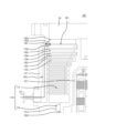
- FIG. 2 is a partially enlarged view of the vacuum pump shown in FIG. 1 .
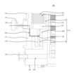
- FIG. 2 is a partial enlarged view showing a first modified example of the vacuum pump shown in FIG. 1 .
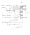
- FIG. 2 is a partial enlarged view showing a second modified example of the vacuum pump shown in FIG. 1 .
- FIG. 2 is a partial enlarged view showing a third modified example of the vacuum pump shown in FIG. 1 .
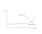
- FIG. 4 is a partial enlarged view showing a fourth modified example of the vacuum pump shown in FIG. 6 is a graph showing the relationship between back pressure and suction pressure in the vacuum pump shown in FIGS. 1 and 5 .
- turbomolecular pump which is one embodiment of a vacuum pump according to the present invention, with reference to the drawings.
- FIG. 1 A longitudinal cross-sectional view of this turbomolecular pump 100 is shown in FIG. 1.
- the turbomolecular pump 100 has an intake port 101 formed at the upper end of a cylindrical outer tube 127. Inside the outer tube 127, a rotor 103 is provided, with a plurality of rotors 102 (102a, 102b, 102c, ...) which are turbine blades for drawing in and exhausting gas (intake gas) and arranged radially around its periphery in multiple stages.
- a rotor shaft 113 is attached to the center of this rotor 103, and this rotor shaft 113 is supported in the air and its position is controlled by, for example, a five-axis controlled magnetic bearing.
- the rotor 103 is generally made of a metal such as aluminum or an aluminum alloy.
- the upper radial electromagnets 104 are arranged in pairs on the X-axis and Y-axis.
- Four upper radial sensors 107 are provided adjacent to the upper radial electromagnets 104 and corresponding to each of the upper radial electromagnets 104.
- the upper radial sensors 107 are, for example, inductance sensors or eddy current sensors having conductive windings, and detect the position of the rotor shaft 113 based on the change in inductance of the conductive winding, which changes according to the position of the rotor shaft 113.
- the upper radial sensors 107 are configured to detect the radial displacement of the rotor shaft 113, i.e., the rotating body 103 fixed thereto, and send it to a control device (not shown).
- a compensation circuit having a PID adjustment function generates an excitation control command signal for the upper radial electromagnet 104 based on the position signal detected by the upper radial sensor 107, and the amplifier circuit 150 (described later) shown in FIG. 2 controls the excitation of the upper radial electromagnet 104 based on this excitation control command signal, thereby adjusting the upper radial position of the rotor shaft 113.
- the rotor shaft 113 is made of a material with high magnetic permeability (iron, stainless steel, etc.) and is attracted by the magnetic force of the upper radial electromagnet 104. Such adjustment is performed independently in the X-axis direction and the Y-axis direction.
- the lower radial electromagnet 105 and the lower radial sensor 108 are arranged in the same manner as the upper radial electromagnet 104 and the upper radial sensor 107, and adjust the lower radial position of the rotor shaft 113 in the same manner as the upper radial position.
- a compensation circuit having, for example, a PID adjustment function generates excitation control command signals for the axial electromagnet 106A and the axial electromagnet 106B based on the axial position signal detected by the axial sensor 109, and the amplifier circuit 150 controls the excitation of the axial electromagnet 106A and the axial electromagnet 106B based on these excitation control command signals, so that the axial electromagnet 106A attracts the metal disk 111 upward by magnetic force, and the axial electromagnet 106B attracts the metal disk 111 downward, thereby adjusting the axial position of the rotor shaft 113.
- control device appropriately adjusts the magnetic force that the axial electromagnets 106A, 106B exert on the metal disk 111, magnetically levitating the rotor shaft 113 in the axial direction and holding it in space without contact.
- the amplifier circuit 150 that controls the excitation of the upper radial electromagnet 104, the lower radial electromagnet 105, and the axial electromagnets 106A, 106B will be described later.
- the motor 121 has multiple magnetic poles arranged circumferentially to surround the rotor shaft 113. Each magnetic pole is controlled by a control device so as to rotate the rotor shaft 113 via electromagnetic forces acting between the magnetic poles and the rotor shaft 113.
- the motor 121 incorporates a rotational speed sensor such as a Hall element, resolver, or encoder (not shown), and the rotational speed of the rotor shaft 113 is detected by the detection signal of this rotational speed sensor.
- phase sensor (not shown) is attached near the lower radial sensor 108 to detect the phase of rotation of the rotor shaft 113.
- the control device uses the detection signals of both this phase sensor and the rotation speed sensor to detect the position of the magnetic pole.
- the fixed blades 123 are arranged with a small gap between the rotating blades 102 (102a, 102b, 102c).
- the rotating blades 102 (102a, 102b, 102c%) are formed at a predetermined angle from a plane perpendicular to the axis of the rotor shaft 113 in order to transport the intake gas molecules downwards by collision.
- the fixed blades 123 (123a, 123b, 123c%) are made of metals such as aluminum, iron, stainless steel, copper, etc., or alloys containing these metals as components.
- the fixed wing spacer 125 is a ring-shaped member made of metal such as aluminum, iron, stainless steel, copper, or an alloy containing these metals as components.
- An outer cylinder 127 is fixed to the outer periphery of the fixed wing spacer 125 with a small gap between them.
- a base portion 129 is disposed at the bottom of the outer cylinder 127.
- An exhaust port 133 is formed in the base portion 129 and is connected to the outside. The intake gas that enters the intake port 101 from the chamber (vacuum chamber) side and is transferred to the base portion 129 is sent to the exhaust port 133.
- This cylindrical portion 102d is cylindrical and protrudes toward the inner peripheral surface of the threaded spacer 131, and is adjacent to the inner peripheral surface of the threaded spacer 131 with a predetermined gap therebetween.
- the intake gas transferred to the thread groove 131a by the rotor 102 and the fixed blade 123 is guided by the thread groove 131a and sent to the base part 129.
- the exhaust section 114 is composed of a turbine pump section 115 having multiple stages of rotors 102 and fixed blades 123, and a drag pump section 116 having a screw groove 131a and a cylindrical section 102d.
- the base portion 129 is a disk-shaped member that forms the base of the turbomolecular pump 100, and is generally made of a metal such as iron, aluminum, or stainless steel.
- the base portion 129 not only physically holds the turbomolecular pump 100, but also functions as a heat conduction path, so it is desirable to use a metal that is rigid and has high thermal conductivity, such as iron, aluminum, or copper.
- the temperature of the rotor 102 rises due to frictional heat generated when the intake gas comes into contact with the rotor 102 and conduction of heat generated by the motor 121, but this heat is transferred to the fixed blade 123 side by radiation or conduction by gas molecules of the intake gas.
- the fixed blade spacers 125 are joined together at their outer periphery and transmit to the outside heat received by the fixed blades 123 from the rotor blades 102 and frictional heat generated when the intake gas comes into contact with the fixed blades 123.
- the threaded spacer 131 is disposed on the outer periphery of the cylindrical portion 102d of the rotor 103, and that the thread groove 131a is engraved on the inner periphery of the threaded spacer 131.
- a thread groove is engraved on the outer periphery of the cylindrical portion 102d, and a spacer having a cylindrical inner periphery is disposed around it.
- the intake gas sucked in from the intake port 101 does not enter the electrical equipment section, which is composed of the upper radial electromagnet 104, upper radial sensor 107, motor 121, lower radial electromagnet 105, lower radial sensor 108, axial electromagnets 106A and 106B, and axial sensor 109, etc., and the electrical equipment section is surrounded by a stator column 122, and the inside of this stator column 122 is kept at a predetermined pressure by purge gas.
- the electrical equipment section which is composed of the upper radial electromagnet 104, upper radial sensor 107, motor 121, lower radial electromagnet 105, lower radial sensor 108, axial electromagnets 106A and 106B, and axial sensor 109, etc.
- a purge gas inlet 135 is provided in the base portion 129, and purge gas is introduced from this purge gas inlet 135 to the inside of the stator column 122.
- the introduced purge gas is sent to the exhaust port 133 through gaps between the protective bearing 120 and the rotor shaft 113, between the rotor and stator of the motor 121, and between the stator column 122 and the inner cylindrical portion of the rotor 102.
- the flow path through which the purge gas flows from the purge gas inlet 135 to the stator column 122 is referred to as the purge gas flow path FP2.
- the turbomolecular pump 100 requires control based on the model identification and individually adjusted unique parameters (for example, various characteristics corresponding to the model).
- the turbomolecular pump 100 has an electronic circuit section 141 inside its body.
- the electronic circuit section 141 is composed of a semiconductor memory such as an EEP-ROM, electronic components such as semiconductor elements for accessing the memory, and a substrate 143 for mounting these components.
- This electronic circuit section 141 is housed below a rotational speed sensor (not shown) near the center of the base section 129 that constitutes the lower part of the turbomolecular pump 100, and is closed by an airtight bottom cover 145.
- some process gases introduced into the chamber have the property of solidifying when their pressure exceeds a predetermined value or their temperature falls below a predetermined value.
- the pressure of the intake gas is lowest at the intake port 101 and highest at the exhaust port 133. If the pressure of the intake gas exceeds a predetermined value or the temperature falls below a predetermined value while the intake gas is being transferred from the intake port 101 to the exhaust port 133, the intake gas solidifies and adheres to and accumulates inside the turbomolecular pump 100.
- a heater (not shown) or a circular water-cooled tube 149 is wrapped around the outer periphery of the base portion 129, and a temperature sensor (e.g., a thermistor) (not shown) is embedded in the base portion 129, and the heating of the heater and the cooling by the water-cooled tube 149 are controlled based on the signal from the temperature sensor to keep the temperature of the base portion 129 at a constant high temperature (set temperature) (hereinafter referred to as TMS; TMS; Temperature Management System).
- TMS constant high temperature
- turbomolecular pump 100 of this embodiment is equipped with an intermediate introduction gas inlet 137 for introducing intermediate introduction gas into the turbomolecular pump 100.
- intermediate introduction gas etc.
- one end of the electromagnet winding 151 constituting the upper radial electromagnet 104 etc. is connected to the positive pole 171a of the power supply 171 via the transistor 161, and the other end is connected to the negative pole 171b of the power supply 171 via the current detection circuit 181 and the transistor 162.
- the transistors 161 and 162 are so-called power MOSFETs, and have a structure in which a diode is connected between the source and drain.
- the transistor 161 has its diode cathode terminal 161a connected to the positive electrode 171a, and its anode terminal 161b connected to one end of the electromagnet winding 151.
- the transistor 162 has its diode cathode terminal 162a connected to the current detection circuit 181, and its anode terminal 162b connected to the negative electrode 171b.
- the current regeneration diode 165 has its cathode terminal 165a connected to one end of the electromagnet winding 151 and its anode terminal 165b connected to the negative pole 171b.
- the current regeneration diode 166 has its cathode terminal 166a connected to the positive pole 171a and its anode terminal 166b connected to the other end of the electromagnet winding 151 via a current detection circuit 181.
- the current detection circuit 181 is composed of, for example, a Hall sensor type current sensor or an electrical resistance element.
- the amplifier circuit 150 configured as above corresponds to one electromagnet. Therefore, if the magnetic bearing is controlled in five axes and there are a total of ten electromagnets 104, 105, 106A, and 106B, a similar amplifier circuit 150 is configured for each electromagnet, and the ten amplifier circuits 150 are connected in parallel to the power supply 171.
- the amplifier control circuit 191 is configured, for example, by a digital signal processor section (hereinafter referred to as a DSP section) of the control device (not shown), and this amplifier control circuit 191 switches the transistors 161 and 162 on and off.
- a DSP section digital signal processor section
- the amplifier control circuit 191 compares the current value detected by the current detection circuit 181 (a signal reflecting this current value is called a current detection signal 191c) with a predetermined current command value. Then, based on the result of this comparison, it determines the size of the pulse width (pulse width times Tp1, Tp2) to be generated within a control cycle Ts, which is one period under PWM control. As a result, gate drive signals 191a, 191b having this pulse width are output from the amplifier control circuit 191 to the gate terminals of transistors 161, 162.
- a high voltage of about 50 V is used for the power supply 171 so that the current flowing through the electromagnet winding 151 can be rapidly increased (or decreased).
- a capacitor (not shown) is usually connected between the positive pole 171a and the negative pole 171b of the power supply 171 to stabilize the power supply 171.
- electromagnet current iL the current flowing through the electromagnet winding 151
- electromagnet current iL the current flowing through the electromagnet winding 151
- both transistors 161 and 162 are turned on for a time period equivalent to pulse width time Tp1 only once during control cycle Ts (e.g., 100 ⁇ s) as shown in FIG. 3. Therefore, during this period, electromagnet current iL increases toward current value iLmax (not shown) that can flow from positive pole 171a to negative pole 171b via transistors 161 and 162.
- both transistors 161 and 162 are turned off for a time period equivalent to pulse width time Tp2 only once during control cycle Ts, as shown in FIG. 4. Therefore, during this period, electromagnet current iL decreases toward current value iLmin (not shown) that can be regenerated from negative pole 171b to positive pole 171a via diodes 165 and 166.
- the intermediate introduction gas is a gas with a higher viscosity than the intake gas.
- the intake gas is hydrogen gas
- nitrogen gas or argon gas is used as the intermediate introduction gas.
- the intermediate introduction gas is not limited to a gas of a different type from the intake gas, and may be, for example, a gas of the same type as the intake gas, but with its viscosity increased by increasing its temperature.
- the intermediate introduction gas is introduced into the turbomolecular pump 100 from the intermediate introduction gas inlet 137 shown in FIG. 5.
- the intermediate introduction gas introduced into the turbomolecular pump 100 flows through the introduction flow path FP3 shown in the figure.
- the fixed blade spacer 125a of this embodiment has a connection port 138 that penetrates the fixed blade spacer 125a in the radial direction, and as shown in the figure, the connection port 138 is located downstream of the rotor 102a in the exhaust direction.
- the introduction flow path FP3 is connected by the connection port 138 to the gas flow path FP1 downstream of the rotor 102a that is closest to the intake port 101 in the exhaust section 114.
- the turbomolecular pump 100 configured in this manner, not only the intake gas sucked in from the intake port 101 but also the intermediate introduction gas that has passed through the connection port 138 flows through the gas flow path FP1.
- the viscosity of the mixture of the intake gas and the intermediate introduction gas is higher than that of the intake gas alone, and therefore the compression effect in the exhaust section 114 (particularly the drag pump section 116) is improved. Therefore, with the turbomolecular pump 100, even if the intake gas is a low-viscosity gas such as hydrogen gas, the back pressure performance can be improved compared to the case where the intermediate introduction gas is not introduced.
- the back pressure performance of the turbo molecular pump 100 in this embodiment will be described with reference to Fig. 10.
- the horizontal axis indicates the pressure (back pressure) at the exhaust port 133
- the vertical axis indicates the pressure (suction pressure) at the intake port 101.
- the dashed line in Fig. 10 indicates the relationship between the back pressure and the suction pressure when only the intake gas is sucked without introducing the intermediate introduction gas
- the solid line in Fig. 10 indicates the relationship between the back pressure and the suction pressure when the intake gas is sucked while introducing the intermediate introduction gas.
- the intake gas is hydrogen gas
- the intermediate introduction gas is nitrogen gas.
- the configuration related to the intermediate gas introduction in the turbomolecular pump 100 can be modified in various ways.
- the turbomolecular pump 100 may be modified to the configuration shown in FIG. 6.
- the turbomolecular pump 100 shown in FIG. 6 is equipped with a valve 139.
- the connection port 138 is provided at the outlet of a through hole provided inside the threaded spacer 131.
- the introduction flow path FP3 through which the intermediate introduction gas flows is a flow path from the valve 139 through the intermediate introduction gas introduction port 137 to the connection port 138.
- the valve 139 can adjust the flow rate of the intermediate introduction gas flowing through the introduction flow path FP3.
- the introduction flow path FP3 is connected to the vicinity of the middle of the drag pump section 116 in the exhaust section 114 by the connection port 138. That is, downstream of the vicinity of the middle of the drag pump section 116 in the exhaust section 114, a mixture of intake gas and intermediate introduction gas flows, so the compression effect in this part is improved compared to when only intake gas flows through the gas flow path FP1. Therefore, even in the turbomolecular pump 100 shown in FIG. 6, the back pressure performance can be improved compared to when the intermediate introduction gas is not introduced. Note that if the amount of intermediate introduction gas introduced into the gas flow path FP1 is too large or too small, the compression effect cannot be improved. On the other hand, if a valve 139 is provided as in this embodiment, the amount of intermediate introduction gas can be easily changed, so that the back pressure performance can be further improved by adjusting the amount of intermediate introduction gas.
- the turbomolecular pump 100 may also be modified to the configuration shown in FIG. 7.
- the turbomolecular pump 100 shown in FIG. 7 is provided with a connection port 138 between the turbine pump section 115 and the drag pump section 116 in the exhaust section 114. That is, the introduction flow path FP3 is connected to the gas flow path FP1 between the turbine pump section 115 and the drag pump section 116. With this configuration, the mixed gas of the intake gas and the intermediate introduction gas flows through the drag pump section 116, improving the compression effect in the drag pump section 116.
- the mixed gas of the intake gas and the intermediate introduction gas basically flows downstream from the middle of the drag pump section 116, while in the turbomolecular pump 100 shown in FIG. 7, the mixed gas basically flows through the entire drag pump section 116, so the compression effect is further improved.
- the mixed gas of the intake gas and the intermediate introduction gas also flows through the entire drag pump section 116 in the turbomolecular pump 100 shown in FIG. 5, so a further improvement in the compression effect is expected compared to the turbomolecular pump 100 in FIG. 6.
- the turbomolecular pump 100 in FIG. 6 In the turbomolecular pump 100 in FIG.
- the number of gas molecules that come into contact with the rotor 102 and the fixed blades 123 when the mixed gas flows through the turbine pump section 115 increases compared to the case of only the intake gas, which increases the heat generation in the rotor 102 and the fixed blades 123, making it easier to reach the upper limit temperature of the turbomolecular pump 100 that is permissible. For this reason, it is necessary to suppress the allowable flow rate of the intake gas in order to suppress the temperature rise.
- the mixed gas basically flows downstream of the turbine pump section 115, so the allowable flow rate of the intake gas can be increased compared to the turbomolecular pump 100 in FIG. 5.
- the turbomolecular pump 100 may be modified to the configuration shown in FIG. 8.
- a purge gas fitting 135a having a purge gas inlet 135 is branched into two on the outside of the base portion 129.
- One of the branched purge gas fittings 135a is connected to the inside of the stator column 122, and the other of the branched purge gas fittings 135a is connected to a connection port 138 located between the turbine pump portion 115 and the drag pump portion 116.
- the purge gas flow path FP2 is a flow path from the purge gas inlet 135 to the stator column 122 via one of the purge gas fittings 135a
- the introduction flow path FP3 is a flow path from the other purge gas fitting 135a to the connection port 138. That is, the introduction flow path FP3 is branched from the purge gas flow path FP2, and a purge gas is used as an intermediate introduction gas flowing through the introduction flow path FP3.
- the turbomolecular pump 100 shown in FIG. 8 allows the purge gas to be used as the intermediate introduction gas, and therefore the overall configuration of the turbomolecular pump 100, including associated equipment, can be simplified compared to when the purge gas and the intermediate introduction gas are prepared separately. Furthermore, when using the turbomolecular pump 100 shown in FIG. 8, it is particularly preferable that the suction gas is hydrogen gas and the purge gas is nitrogen gas. That is, since nitrogen gas has a higher viscosity than hydrogen gas, the back pressure performance can be improved compared to when nitrogen gas is not introduced as the intermediate introduction gas. Furthermore, since nitrogen gas is an inexpensive inert gas, the turbomolecular pump 100 can be operated safely and costs can be reduced.
- the turbomolecular pump 100 may be modified to the configuration shown in FIG. 9.
- the turbomolecular pump 100 shown in FIG. 9 has through holes in the base portion 129 and the threaded spacer 131.
- the inlet of the through hole is connected to the purge gas flow path FP2.
- the through hole is also connected to a connection port 138 located between the turbine pump portion 115 and the drag pump portion 116.
- the introduction flow path FP3 is a flow path from the inlet of the through hole to the connection port 138.
- the flow path located outside the turbomolecular pump 100 i.e., inside the purge gas joint 135b
- the flow path located inside the turbomolecular pump 100 is referred to as the inner purge gas flow path FP2B.
- the introduction flow path FP3 branches off from the inner purge gas flow path FP2B and is connected to the gas flow path FP1. That is, in this turbomolecular pump 100, the purge gas can also be used as the intermediate introduction gas, so the overall configuration of the turbomolecular pump 100 can be simplified compared to when the purge gas and the intermediate introduction gas are prepared separately.
- the introduction flow path FP3 is provided outside the turbomolecular pump 100, so space is required, but in the turbomolecular pump 100 in FIG. 9, the introduction flow path FP3 is provided inside the turbomolecular pump 100, so space can be secured around the turbomolecular pump 100.
- the inner diameter of at least a portion of the introduction flow path FP3 is smaller than the inner diameter of the purge gas flow path FP2.
- a relatively small diameter connection port 138 is used, and the inner diameter of at least this portion is smaller than the inner diameter of the purge gas flow path FP2.
- the amount of purge gas used as the intermediate introduction gas is generally less than the amount of purge gas introduced into the stator column 122. Therefore, by making the inner diameter of at least a portion of the introduction flow path FP3 smaller than the inner diameter of the purge gas flow path FP2, it becomes easier to achieve the desired back pressure performance from the beginning. Furthermore, when adjusting the amount of purge gas flowing through the introduction flow path FP3 to improve the back pressure performance, it is easy to increase a small inner diameter, making the adjustment easier.
- the amount of purge gas flowing through the introduction flow path FP3 may be adjusted using the valve 139 (see Figure 6) described above.
- the drag pump section 116 is not limited to the Holweck pump mechanism that uses the screw groove 131a described above, but may be configured with other pump mechanisms, such as a Sigburn pump mechanism.
Landscapes
- Engineering & Computer Science (AREA)
- Mechanical Engineering (AREA)
- General Engineering & Computer Science (AREA)
- Non-Positive Displacement Air Blowers (AREA)
Abstract
Le problème décrit par la présente invention est de proposer une pompe à vide qui offre d'excellentes performances de contre-pression même lorsque le gaz d'aspiration est de l'hydrogène gazeux ou analogue. La solution selon l'invention porte sur une pompe à vide 100 comprenant une partie échappement 114 qui comprend : une section de pompe à turbine 115 comportant une pluralité d'étages de pales rotatives 102 et de pales fixes 123 ; et une section de pompe de traînée 116 positionnée sur le côté aval d'échappement de la section de pompe à turbine 115. Le gaz d'admission aspiré à partir d'un orifice d'admission 101 par la partie échappement 114 est évacué d'un orifice d'échappement 133 par l'intermédiaire d'un passage d'écoulement de gaz FP1. La pompe à vide 100 est caractérisée en ce qu'elle comprend un passage d'écoulement d'introduction FP3 servant à introduire un gaz d'introduction intermédiaire présentant une viscosité supérieure à celle du gaz d'admission. La pompe à vide 100 est également caractérisée en ce que le passage d'écoulement d'introduction FP3 est relié au passage d'écoulement de gaz FP1 sur le côté aval d'échappement de la pale rotative 102 la plus proche de l'orifice d'admission 101 parmi la pluralité d'étages de pales rotatives 102 dans la partie d'échappement 114.
Priority Applications (1)
| Application Number | Priority Date | Filing Date | Title |
|---|---|---|---|
| CN202480053938.1A CN121794477A (zh) | 2023-08-21 | 2024-08-21 | 真空泵 |
Applications Claiming Priority (2)
| Application Number | Priority Date | Filing Date | Title |
|---|---|---|---|
| JP2023-134192 | 2023-08-21 | ||
| JP2023134192A JP7764434B2 (ja) | 2023-08-21 | 2023-08-21 | 真空ポンプ |
Publications (1)
| Publication Number | Publication Date |
|---|---|
| WO2025041797A1 true WO2025041797A1 (fr) | 2025-02-27 |
Family
ID=94731905
Family Applications (1)
| Application Number | Title | Priority Date | Filing Date |
|---|---|---|---|
| PCT/JP2024/029683 Pending WO2025041797A1 (fr) | 2023-08-21 | 2024-08-21 | Pompe à vide |
Country Status (4)
| Country | Link |
|---|---|
| JP (1) | JP7764434B2 (fr) |
| CN (1) | CN121794477A (fr) |
| TW (1) | TW202509353A (fr) |
| WO (1) | WO2025041797A1 (fr) |
Cited By (1)
| Publication number | Priority date | Publication date | Assignee | Title |
|---|---|---|---|---|
| EP4585807A1 (fr) * | 2025-05-15 | 2025-07-16 | Pfeiffer Vacuum Technology AG | Système à vide et procédé de fonctionnement d'un tel système à vide |
Citations (3)
| Publication number | Priority date | Publication date | Assignee | Title |
|---|---|---|---|---|
| JP5689546B2 (ja) | 2009-08-28 | 2015-03-25 | エドワーズ株式会社 | 真空ポンプ |
| JP2019120249A (ja) * | 2017-12-27 | 2019-07-22 | エドワーズ株式会社 | 真空ポンプおよびこれに用いられる固定部品、排気ポート、制御手段 |
| JP2022135716A (ja) * | 2021-03-05 | 2022-09-15 | エドワーズ株式会社 | 真空ポンプ、及び、真空排気装置 |
-
2023
- 2023-08-21 JP JP2023134192A patent/JP7764434B2/ja active Active
-
2024
- 2024-08-05 TW TW113129162A patent/TW202509353A/zh unknown
- 2024-08-21 WO PCT/JP2024/029683 patent/WO2025041797A1/fr active Pending
- 2024-08-21 CN CN202480053938.1A patent/CN121794477A/zh active Pending
Patent Citations (3)
| Publication number | Priority date | Publication date | Assignee | Title |
|---|---|---|---|---|
| JP5689546B2 (ja) | 2009-08-28 | 2015-03-25 | エドワーズ株式会社 | 真空ポンプ |
| JP2019120249A (ja) * | 2017-12-27 | 2019-07-22 | エドワーズ株式会社 | 真空ポンプおよびこれに用いられる固定部品、排気ポート、制御手段 |
| JP2022135716A (ja) * | 2021-03-05 | 2022-09-15 | エドワーズ株式会社 | 真空ポンプ、及び、真空排気装置 |
Cited By (1)
| Publication number | Priority date | Publication date | Assignee | Title |
|---|---|---|---|---|
| EP4585807A1 (fr) * | 2025-05-15 | 2025-07-16 | Pfeiffer Vacuum Technology AG | Système à vide et procédé de fonctionnement d'un tel système à vide |
Also Published As
| Publication number | Publication date |
|---|---|
| JP2025029487A (ja) | 2025-03-06 |
| TW202509353A (zh) | 2025-03-01 |
| CN121794477A (zh) | 2026-04-03 |
| JP7764434B2 (ja) | 2025-11-05 |
Similar Documents
| Publication | Publication Date | Title |
|---|---|---|
| JP7619871B2 (ja) | ターボ分子ポンプ | |
| WO2025041797A1 (fr) | Pompe à vide | |
| JP7689448B2 (ja) | 真空ポンプ | |
| JP7680226B2 (ja) | 真空ポンプ | |
| JP7634372B2 (ja) | 真空ポンプ、回転体およびカバー部 | |
| JP7696210B2 (ja) | 真空ポンプ | |
| JP7546412B2 (ja) | 真空ポンプ、固定翼、およびスペーサ | |
| KR20250016163A (ko) | 진공 펌프 및 진공 배기 시스템 | |
| EP4194699A1 (fr) | Pompe à vide et pale de rotor pour pompe à vide | |
| KR20230116781A (ko) | 진공 펌프 | |
| KR20260051378A (ko) | 진공 펌프 | |
| JP7712252B2 (ja) | 真空ポンプ | |
| JP7787120B2 (ja) | 真空ポンプ | |
| JP7652576B2 (ja) | 真空ポンプ及びスペーサ | |
| JP7671586B2 (ja) | 真空ポンプとその回転体 | |
| JP7555227B2 (ja) | 真空ポンプとこれを用いた真空排気システム | |
| JP7668765B2 (ja) | 真空ポンプ、制御装置および制御方法 | |
| JP7625548B2 (ja) | 真空ポンプ | |
| JP7463324B2 (ja) | 真空ポンプ及び真空ポンプの熱移動抑制部材 | |
| JP7788416B2 (ja) | 真空ポンプ及び真空ポンプの制御装置 | |
| JP7689823B2 (ja) | 真空ポンプ | |
| JP7614247B2 (ja) | 真空ポンプ、磁気軸受制御装置、および圧縮解凍方法 | |
| JP7530939B2 (ja) | 真空ポンプおよび固定部品 | |
| WO2025047543A1 (fr) | Pompe à vide, disque fixe et composant adapté | |
| EP4227536A1 (fr) | Pompe à vide et corps cylindrique rotatif installé dans une pompe à vide |
Legal Events
| Date | Code | Title | Description |
|---|---|---|---|
| 121 | Ep: the epo has been informed by wipo that ep was designated in this application |
Ref document number: 24856485 Country of ref document: EP Kind code of ref document: A1 |
|
| WWE | Wipo information: entry into national phase |
Ref document number: 2024856485 Country of ref document: EP |
|
| NENP | Non-entry into the national phase |
Ref country code: DE |