EP0021064A1 - Verfahren zur Herstellung eines Kompostes - Google Patents
Verfahren zur Herstellung eines Kompostes Download PDFInfo
- Publication number
- EP0021064A1 EP0021064A1 EP19800102914 EP80102914A EP0021064A1 EP 0021064 A1 EP0021064 A1 EP 0021064A1 EP 19800102914 EP19800102914 EP 19800102914 EP 80102914 A EP80102914 A EP 80102914A EP 0021064 A1 EP0021064 A1 EP 0021064A1
- Authority
- EP
- European Patent Office
- Prior art keywords
- agitator
- zone
- materials
- disposed
- heaping
- Prior art date
- Legal status (The legal status is an assumption and is not a legal conclusion. Google has not performed a legal analysis and makes no representation as to the accuracy of the status listed.)
- Granted
Links
- 238000009264 composting Methods 0.000 title claims abstract description 30
- 238000000034 method Methods 0.000 title claims abstract description 16
- 239000011368 organic material Substances 0.000 claims abstract description 36
- 239000000463 material Substances 0.000 claims description 56
- 238000007790 scraping Methods 0.000 claims description 3
- 238000006073 displacement reaction Methods 0.000 description 7
- 238000010564 aerobic fermentation Methods 0.000 description 4
- 238000010276 construction Methods 0.000 description 4
- 238000000855 fermentation Methods 0.000 description 4
- 230000004151 fermentation Effects 0.000 description 4
- 238000009434 installation Methods 0.000 description 4
- 238000012545 processing Methods 0.000 description 4
- 230000007246 mechanism Effects 0.000 description 3
- 238000012856 packing Methods 0.000 description 3
- 238000005192 partition Methods 0.000 description 3
- 238000013019 agitation Methods 0.000 description 2
- 230000008859 change Effects 0.000 description 2
- 239000002361 compost Substances 0.000 description 2
- 238000007599 discharging Methods 0.000 description 2
- 230000000694 effects Effects 0.000 description 2
- 230000005484 gravity Effects 0.000 description 2
- 238000012423 maintenance Methods 0.000 description 2
- 230000000149 penetrating effect Effects 0.000 description 2
- 230000008569 process Effects 0.000 description 2
- 230000008901 benefit Effects 0.000 description 1
- 230000000903 blocking effect Effects 0.000 description 1
- 238000000151 deposition Methods 0.000 description 1
- 230000029142 excretion Effects 0.000 description 1
- 238000009313 farming Methods 0.000 description 1
- 230000000977 initiatory effect Effects 0.000 description 1
- 230000004048 modification Effects 0.000 description 1
- 238000012986 modification Methods 0.000 description 1
- 230000001737 promoting effect Effects 0.000 description 1
- 239000010802 sludge Substances 0.000 description 1
- 239000013598 vector Substances 0.000 description 1
- 239000002699 waste material Substances 0.000 description 1
Images




Classifications
-
- C—CHEMISTRY; METALLURGY
- C05—FERTILISERS; MANUFACTURE THEREOF
- C05F—ORGANIC FERTILISERS NOT COVERED BY SUBCLASSES C05B, C05C, e.g. FERTILISERS FROM WASTE OR REFUSE
- C05F17/00—Preparation of fertilisers characterised by biological or biochemical treatment steps, e.g. composting or fermentation
- C05F17/90—Apparatus therefor
- C05F17/921—Devices in which the material is conveyed essentially horizontally between inlet and discharge means
- C05F17/943—Means for combined mixing and conveying
-
- C—CHEMISTRY; METALLURGY
- C05—FERTILISERS; MANUFACTURE THEREOF
- C05F—ORGANIC FERTILISERS NOT COVERED BY SUBCLASSES C05B, C05C, e.g. FERTILISERS FROM WASTE OR REFUSE
- C05F17/00—Preparation of fertilisers characterised by biological or biochemical treatment steps, e.g. composting or fermentation
- C05F17/90—Apparatus therefor
- C05F17/921—Devices in which the material is conveyed essentially horizontally between inlet and discharge means
- C05F17/939—Means for mixing or moving with predetermined or fixed paths, e.g. rails or cables
-
- Y—GENERAL TAGGING OF NEW TECHNOLOGICAL DEVELOPMENTS; GENERAL TAGGING OF CROSS-SECTIONAL TECHNOLOGIES SPANNING OVER SEVERAL SECTIONS OF THE IPC; TECHNICAL SUBJECTS COVERED BY FORMER USPC CROSS-REFERENCE ART COLLECTIONS [XRACs] AND DIGESTS
- Y02—TECHNOLOGIES OR APPLICATIONS FOR MITIGATION OR ADAPTATION AGAINST CLIMATE CHANGE
- Y02P—CLIMATE CHANGE MITIGATION TECHNOLOGIES IN THE PRODUCTION OR PROCESSING OF GOODS
- Y02P20/00—Technologies relating to chemical industry
- Y02P20/141—Feedstock
- Y02P20/145—Feedstock the feedstock being materials of biological origin
-
- Y—GENERAL TAGGING OF NEW TECHNOLOGICAL DEVELOPMENTS; GENERAL TAGGING OF CROSS-SECTIONAL TECHNOLOGIES SPANNING OVER SEVERAL SECTIONS OF THE IPC; TECHNICAL SUBJECTS COVERED BY FORMER USPC CROSS-REFERENCE ART COLLECTIONS [XRACs] AND DIGESTS
- Y02—TECHNOLOGIES OR APPLICATIONS FOR MITIGATION OR ADAPTATION AGAINST CLIMATE CHANGE
- Y02W—CLIMATE CHANGE MITIGATION TECHNOLOGIES RELATED TO WASTEWATER TREATMENT OR WASTE MANAGEMENT
- Y02W30/00—Technologies for solid waste management
- Y02W30/40—Bio-organic fraction processing; Production of fertilisers from the organic fraction of waste or refuse
Definitions
- the present invention relates generally to treatment of organic materials such as those discharged as municipal waste, organic sludge or excretions from stock farming and, more particularly, to a method and apparatus for converting such organic materials into compost.
- the organic materials to be composted are fed to a composting area or zone,the plan view of which is generally a rectangular shape,at an inlet of the composting zone and progressively displaced towards a discharge port of the composting zone by a revolving means adapted to travel in a zig-zag fashion within the composting zone so as to loosen or free the materials piled in the composting zone and incrementally displace the same from the inlet towards the outlet in a zig-zag course of travel.
- the rotational speed and the travelling speed of the revolving means are so selected so that the organic materials are loosened or freed and fed in a direction traversing the zig-zag travelling passage of the revolving means by a distance enough to pass beyond over the revolving means and laid on the composting zone again where the materials are deposited rather loosely without packing into a mass whereby aerobic fermentation is not prevented.
- the revolving means above thus, effects simultaneously agitation and displacement of the materials to be composted and travels substantially over the entire surface of the composting zone. Due to such arrangement, the capacity of the composting apparatus is able to be increased without making the mechanism for displacing and agitating the materials substantially large in size. Such increase of the capacity is also materialized economically.
- Fig. 1 there is shown a schematic drawing of a plan view for illustrating a principle of the present invention.
- the composting process is carried out over an area or zone X of a generally rectangular shape.
- An agitating device 1 is arranged to be movable in the zone X while it is given a function to displace organic materials to be composted in a direction of an arrow 2. Assuming that the organic materials are laid to cover the entire zone, the device 1 may start its movement from a starting point 4 adjacent a discharge end 3 and travels zig-zag in the directions indicated by arrows 5 and 5' traversing the displacement direction 2 and arrows 6 and 6' parallel to the direction 2.
- the agitation device 1 When the agitation device 1 reaches a terminal point adjacent a supply or feed end 7, all the materials have been displaced in the direction of arrow 2 by a distance of displacement effected by one passage of the agitating device 1 in the direction 6 or 6'. Upon reaching the terminal point 8, the agitating device 1 will return along a path 11 in a direction of an arrow 12, which is separated from a fermentation path 10 in the zone X by a partition wall 9 so as to be free of composting materials, and again reaches the starting point 4.
- the partition wall 9 may be omitted provided that mechanism is associated with the device 1 for lifting agitating means upwardly above the height of the composting materials piled or deposited in the zone so as to clear the agitating means from the composting materials while the device is returning from the point 8 to the point 4.
- Figs. 2 and 3 There may be another locus or locuses of movement or travel of the device 1. Examples of such locuses are illustrated in Figs. 2 and 3.
- Fig. 2 the locus is shown in case the travel of the device follows-in a direction of resultant vectors of the material displacement and those parallel and normal to the displacement. Such directions are shown as arrows 13 and 13' in Fig. 2 in place of the arrows 6 and 6' in Fig. 1.
- the device travels on the same path as indicated by overlapped arrows 5 and 5' and advances toward the feed end by a distance equal to a pitch of zig-zag along the arrow 6' without travelling along the arrow 6 shown in Fig. 1.
- FIGs. 4, 5 and 6 there is shown an embodiment of the present invention in which composting operation is performed indoors.
- a fermenting chamber 15 is enclosed within or covered by a shelter 16 and a compost material heaping or depositing zone 17 of a generally rectangular shape is provided on a floor 18 of the shelter and the materials before the composting operation, under the fermentation and after the fermentation are heaped in the zone 17 as a piled layer 19.
- the floor 18 of the zone 17 is provided with a plurality of perforations 20 through which air is injected upwardly from an air chamber 21 below the floor 18 so as to promote the aerobic fermentation, the air chamber,21 being connected to an air source 22.
- One of the edges of the rectangular heaping zone 17 is adapted to receive organic materials to be composted and, for convenience, it is referred to as a material charging or inlet port 23 and the edge opposite the port 23 is a discharge or outlet port 23 for discharging the fermented materials outwardly.
- a material charging or inlet port 23 and the edge opposite the port 23 is a discharge or outlet port 23 for discharging the fermented materials outwardly.
- the materials are advanced or displaced in the direction of arrow A from the inlet port 23 towards the outlet port 24 by a revolving means illustrated as an agitator 25 which is adapted to travel a zig-zag course as illustrated in Figs. 1, 2 and 3.
- a carriage 26 is provided to move back and forth over the floor 18 and between the ports 23 and 24.
- the carriage 26 extends transversely to the direction A and is movably supported at oppostie ends by a pair of guide rails 14 mounted on the side walls or columns of the shelter 16.
- the carriage 26 is adapted to movably support a carrier 27 which is arranged to run on the carriage 26 in the lengthwise direction thereof.
- the carrier 27 suspends the agitator 25 so that the agitator 25 may follow the zig-zag path when the carriage 26 moves intermittently and incrementally in a direction B opposite to the direction A and continuously in the direction A, and the carrier moves transversly to the directions A and B on the carriage 25 while the movement of the carriage is stopped.
- the agitator 25 is now described together with its accompanying elements and/or cooperating elements referring to Figs. 7, 8 and 9.
- the agitator 25 is suspended by an arm 28 at a lower portion thereof which extends downwardly from the carrier 27.
- the agitator 25 comprises a rotatable shaft 29 extending parallely to the moving direction of the carrier or the longitudinal direction of the carriage 26, plural number of scraper blades 30 radially mounted on the shaft 29 and a motor 31 for rotatably driving the shaft 29.
- the rotation of the scraper blades 30 scrapes up the piled layer 19 of the organic materials and send the materials flying in a direction S shown in Fig. 8 so that the scraped materials are displaced in the direction of A opposite the direction of B.
- the position of the agitator 25 is adjusted so that the bottom of the circumscribed circle of the tips of the scraper blades 30 is slightly above the floor 18.
- a motor 32 is provided for effecting the movement of the carrier 27 on the carriage 26 and a motor 33 is provided for effecting the intermittent or continuous movement of the carriage 26.
- a return path 34 is provided adjacent the heaping zone 17 in order to facilitate the return movement of the agitator 25, the path 34 being arranged to be substantially free from the organic materials or piled layer 19.
- the path 34 is substantially the same as the path 11 in Fig. 1 and a partition wall (not shown) similar to 9 shown in Fig. 1 may also be provided between the path 34 and the zone 17.
- the path 34 is naturally made wide enough to allow the movement of the agitator therealong without interference.
- Figs. 4 through 9 The operation of the embodiment illustrated in Figs. 4 through 9 is performed in a manner substantially the same as that illustrated in Fig. 3. Assuming that the piled layer 19 of the organic materials covers the entire surface area of the heaping zone 17 some part thereof having been alreadly completely fermented and the other part thereof being under fermentation, the agitator 25 is arranged to commence its zig-zag course at a point "a l " shown in Fig. 6 which corresponds to the point 4 in Fig. 3. With initiation of the revolution of the agitator 25 as schematically shown in Figs.
- the carrier 27 is also initiated to move on the carriage 26 from the side of the point “a l “ toward a point “b l “ opposite the point “a 1 " and thence back again to the point”ai while the movement of the carriage in the direction B is suspended during the back and forth movement of the carrier 27 between the points “a l “ and “b l “ corresponding to the first travel passage shown at the left end line in Fig. 3.
- the points "a 1 " and "b l " have been added to in Fig. 3 to where they correspond.
- During the reciprocal movement of the carrier 26 from the point “a 1 " to the point "b l “ composted organic materials are displaced in the direction of A toward the outlet port 24.
- the distance of the pitch "p" is determined to be equivalent to the dimention of the rotating scraper blades 30 proper for penetrating into the piled layer 19 for displacing the piled layer in the direction A.
- the piled layer is displaced as a whole by a distance equivalent to the mean value "d" of the displacement of the materials scraped from the intermediate edge line 35 of the piled layer to be penetrated by the blades 30 to the intermediate edge line 36 of the layer of the materials thrown and re-piled on the floor by the rotation of the agitator as shown in Fig. 8.
- the agitator 25 is returned to the starting point "a 1 " and the operation above is repeated.
- the organic materials are also charged through the inlet port in an appropriate amount to keep the operation continuous.
- the amount of the organic materials equivalent to that displaced by one transverse movement of the agitator must be charged through the inlet port 23 per one complete zig-zag course of the agitator 25 to keep the operation continuous.
- the actuations of the respective motors 31, 32 and 33 are controlled by a control unit 37 accompanied by position responsive means such as limit switches or timing means well known in the art.
- FIGs. 10 and 11 another embodiment of the present invention is illustrated which is adapted to be used indoors as well as outdoors.
- the elements similar to those in the first embodiment of Figs. 4 through 9 with respect to the functions are given with the same reference as those in the first embodiment with a suffix "a" added to each thereof, respectively.
- a carriage beam 28a equivalent to the carriage 28 in the first embodiment is provided with a pair of supporting legs 38 at the opposite end thereof to form a structure resembling a gateway 39.
- the gateway structure 39 is arranged to move in the direction A or B on a pair of floor or ground rails 39 extending transversely of the longitudinal direction of the carriage beam 28a.
- agitators 25a are disposed at opposite sides of an arm 28a so as to be driven by a motor 31a interposed therebetween.
- the agitators 25a may be operable in either of the moving directions in which a carrier 27a travels.
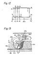
- a locus of the travel of the agitators 25a may be made similar to that shown in Fig. 1. More specifically, the travelling locus of the agitators 25a is schematically illustrated in Fig. 12.
- a heaping zone 17a in this embodiment is provided with a pair of side walls 40 and one of the side walls 40 and one of the supporting legs 38 provide a return track.path 34a therebetween.
- a starting point ⁇ 1 is shifted from a last point ⁇ 1 in the return path 34a to clear the side wall.
- a starting point ⁇ n ' in the return path 34 is displaced from the last point a of the agitating travel locus.
- the agitating travel of the agitators 25a - commences at the point ⁇ 1 and thence follows the zig-zag path as ⁇ 1 ⁇ 1 ⁇ 2 ⁇ 2 whereas ⁇ n ⁇ ⁇ n and moves to the point ⁇ n ' and repeats the operation explained.
- FIGs. 13 and 14 still another embodiment, i.e. a third one according to the present invention, is shown which is similar in function, to the second embodiment.
- the elements and/or portions similar to those in the first embodiment are given the same references as in the first embodiment except that after each of the references the suffix "b" is added.
- a carrier 27b is combined with a downwardly extending arm 28b so that the arm 28b extends diagonally in the direction A as shown in Figs. 13 and 14.
- the arm 28b supports an agitator or agitators 25b at its lower end and, thus, the combination of the carrier 27b, arm 28b and the agitator(s) 25b imposes loads on the carriage beam 26b not only in a vertical direction by gravity but also in a pivoting direction by movement of a force due to the diagonal or canted arrangement of the arm 28b. Accordingly the combination above is movably supported on the surface of .
- Figs. 13 and 14 provides the further advantage that, if an inclination of the arm 28b is determined in connection with the penetrating pitch "p" of the agitator 25b so that the arm 28b itself may not interfere with the piled layer 19b during the transverse movement of the carrier 27b and the arm 28b, provision of the agitator 25b only at one side of the arm 28a in a way similar to that shown in Fig. 9 may present the possibility of following the locus represented in Fig. 12 thereby saving time compared to the locus of travel illustrated in Fig. 3.
- a plurality of composting floors may be provided as a multi-staged shelter.
- Such an example is illustrated in Figs. 15 and 16 as a two two-story shelter 16'.
- the components and elements similar in function to those in the 1st embodiment (Figs. 4 through 9) are given the same references as those corresponding thereto in the 1st embodiment except that the suffix "u" or a "l" is added to each thereof in the upper and lower floors, respectively. Therefore, the operation of this apparatus shown in Figs.
- the organic materials to be composted are delivered by a conveyor belt 44 and charged to an upper heaping zone 17u through an inlet port 23u by distributor 55 adapted to distribute the conveyed materials evenly along the witdh of the inlet port 23u.
- the materials plied in the upper heaping zone are turned over and displaced in a direction of Au by an agitator 25u during the zig-zag course thereof on an upper floor 18u.
- the materials thus displaced gradually fall through an outlet port 24u onto a lower floor 18t at its inlet port 23l from where the materials are further turned over or plowed up and gradually displaced toward an outlet port 24l by an agitator 25l during the zig-zag course thereof on a lower floor 18t and are discharged on a discharging conveyor 46.
- the shelter 16' has been explained as a two staged shelter, it is to be noted that the number of floors may be increased and it is not limited to two as illustrated.
- a still further or 5th embodiment of the present invention which is utilized for the composting materials piled in the open air or in the field.
- the organic materials are agitated and gradually displaced in a direction of A f from an inlet side 23f toward an outlet side 24f by an agitator 25f during its zig-zag movement such as the movement following a path b i ⁇ a i ⁇ a i+1 ⁇ a i+1 .
- the agitator 25f is preferably carried by a vehicle 47 which may be movable to trace the path above.
- each of the tips of the scraper blades 30f in the agitator 25f is shaped to have a "Y" shape as schematically illustrated in Fig. 18a so that it may scrape of a piled layer 19f efficiently irrespective of the rotational directions thereof.
- each of the scraper blades in the foregoing embodiment were given a curvature, respectively so that it may scrape the piled organic materials efficiently since it is unnecessary in those embodiments to reverse the rotational direction.
- the vehicle 47 may take the form of an automobile and, thus, it is preferable to rotate the agitator 25f by utilizing a power take out shaft extended from its engime in lieu of the motors in the previous embodiments.
- Fig. 18b there is shown an illustration similar to that shown in Fig. 18 so that the vehicle 47 is equipped with a front agitator 25 F and a rear agitator 25R.
- the rear agitator 25R throw the materials sent by the forward agitator 25F further and promotes breaking up or fractionizing of the organic materials.
- Figs. 8 and 9 are referenced again. While the movement of the carriage beam 26 in the direction of B is suspended, the agitator 25 is rotated in the direction of the arrow as indicated and traversed in the direction along the longitudinal direction of the beam 26.
- the height "H" of the piled layer 19 is preferably more than half the outer diameter "D" of the scraper blades 30 or it is further preferably more than the value of the outer diameter "Q" so that the organic materials are sent flying in the direction of arrows S in Fig. 8 to pass beyond the agitator 25 in the direction A assisted by blocking effect afforded by the edge of the piled layer deposited in such layer or thickness.
- the blades 30 penetrate the piled layer 19 of the materials, scrape off and send or throw the same flying and, therefore, the materials are divided, or broken up so as to remarkably increase the total surface area of the thrown materials which 4 re gently deposited on the floor 18 without packing down into a mass whereby resistance to air blown upwardly through the piled materials is kept low to facilitate and promote aerobic fermentation.
- the height H' of the piled layer 19 is less than half of the outer diameter "D" of the agitator scraper blades 30 such as shown in Fig. 8a, the rotation of the agitator 25 is preferably reversed as schematically shown in Fig.
- the scraped off materials are sent or thrown inthe direction S' passing the region where the agitator is traversing in a direction normal to the direction A and are gently piled with displacement in the same direction as A.
- the shape of blades such as illustrated in Fig. 18a may be employed if necessary. If the materials are piled high for some reason such as to increase the processing quantity of the materials per unit area, an additional agitator may be provided above the agitator disposed adjacent the floor. Such an arrangement is schematically illustrated in Fig.
- two agitators namely an upper agitator 25U and a lower agitator 25L are arranged to move in a direction vertical to the plane of the illustrated drawing while they are rotated in the direction of the arrows.
- the agitators 25U and 25L are also adapted to intermittently advance in the direction B towards an inlet port of the materials so that they are moved to trace a zig-zag path.
- the upper agitator 25U slightly forward relative to the lower agitator 25L with respect to the advancing direction B in order to allow each of the agitators to penetrate properly into the layer of materials.
- the agitator 25E comprises an endless linkage 50 having a plurality of scraper blades 30E, the linkage 50 being trained around a revolving means (not shown) so as to run in the direction of the arrows and send the organic materials scraped off flying in the same way as explained in the foregoing explanation.
- the agitator 25E is preferably leans backwards so that the upper portion is slightly behind the lower portion with respect to the advancing direction B as illustrated in the drawings.
- Fig. 23 the arrangement of the scraping blades 30 is illustrated so as to correspond to the agitator shown in Figs. 7, 8 and 9.
- the blades 30 are radially mounted on the shaft 29 in the same axial position whereas, in Fig. 23(II), the blades 30 are mounted on the shaft 29 in axially staggered relationship.
- the number and the axial position of the blades are not limited to those illustrated in the drawing and they may be modified as required. It is also preferably to construct the mounting of the blades so replacement thereof is easy.
- a carriage beam 26v is movably supported at its opposite ends by a pair of guide rails 14v.
- a carrier 27v is disposed on the carriage beam so as to move along the lengthwise direction of the beam 26v.
- Two vertical shafts 29v arranged to be driven by motors.32v are rotatably suspended from the carrier 27v and extend downwardly therefrom.
- Each shaft 29v is provided with a plurality of axial blades 30b radially mounted on the shaft 29b at the longitudinal edges thereof to construct an agitator 25v.
- Both the agitators 25v thus constructed are arranged to rotate in the same direction as indicated by arrows, in Fig. 26 during the movement of the carrier 27v on the carriage beam 26v or in the direction of 5v or 5v' traversing the direction of A or B so that the organic materials are agitated and displaced in the direction A. Since the rotational direction of the agitators 25v is to be reversed depending on the direction in which the carrier 27v is moving, the respective longitudinal edges of the blades 30b are preferably given "Y" shape similar to that shown in Fig. 18a.
- an agitator 25B in this embodiment comprises a rotatable core 60 of a disk shape supported at the lower portion of an arm 62 extending from a carrier (not shown but similar to those explained in the foregoing embodiments) and a plurality of buckets 61 mounted on the periphery of the core 60.
- a carrier not shown but similar to those explained in the foregoing embodiments
- Each of. the buckets 61 is provided with an edge 63 at the outer end thereof as well as side edges 64 thereby promoting the scraping effect thereof.
Landscapes
- Chemical & Material Sciences (AREA)
- Chemical Kinetics & Catalysis (AREA)
- Life Sciences & Earth Sciences (AREA)
- Engineering & Computer Science (AREA)
- Biochemistry (AREA)
- Biotechnology (AREA)
- Health & Medical Sciences (AREA)
- General Chemical & Material Sciences (AREA)
- Microbiology (AREA)
- Molecular Biology (AREA)
- Organic Chemistry (AREA)
- Fertilizers (AREA)
- Processing Of Solid Wastes (AREA)
Applications Claiming Priority (4)
| Application Number | Priority Date | Filing Date | Title |
|---|---|---|---|
| JP65249/79 | 1979-05-26 | ||
| JP54065249A JPS5838395B2 (ja) | 1979-05-26 | 1979-05-26 | 堆肥化方法及びその装置 |
| JP54087576A JPS5855118B2 (ja) | 1979-07-11 | 1979-07-11 | 堆肥化装置 |
| JP87576/79 | 1979-07-11 |
Publications (2)
| Publication Number | Publication Date |
|---|---|
| EP0021064A1 true EP0021064A1 (de) | 1981-01-07 |
| EP0021064B1 EP0021064B1 (de) | 1989-08-30 |
Family
ID=26406375
Family Applications (1)
| Application Number | Title | Priority Date | Filing Date |
|---|---|---|---|
| EP19800102914 Expired EP0021064B1 (de) | 1979-05-26 | 1980-05-24 | Verfahren zur Herstellung eines Kompostes |
Country Status (5)
| Country | Link |
|---|---|
| US (2) | US4410348A (de) |
| EP (1) | EP0021064B1 (de) |
| DE (1) | DE3020011A1 (de) |
| FR (1) | FR2457847A1 (de) |
| IT (1) | IT1197457B (de) |
Cited By (6)
| Publication number | Priority date | Publication date | Assignee | Title |
|---|---|---|---|---|
| US4410348A (en) * | 1979-05-26 | 1983-10-18 | Ebara Corporation | Method for composting |
| AT386821B (de) * | 1985-06-14 | 1988-10-25 | Vogel Werner Ing | Einrichtung zum umsetzen von muell auf einem kompostierfeld |
| WO1993016017A1 (en) * | 1992-02-12 | 1993-08-19 | Ntp-Yhtymä Oy | Mechanical composting |
| WO1995015933A1 (en) * | 1993-12-06 | 1995-06-15 | Bioplan A/S | A composting plant for organic waste and method for composting such waste |
| EP0768286A1 (de) * | 1995-10-11 | 1997-04-16 | Ebara Corporation | Horizontalschaufelrad enthaltende Fermentationsanlage und Verfahren zum Betrieb derselben |
| WO2014095390A1 (de) * | 2012-12-21 | 2014-06-26 | Tsp Gmbh | Vorrichtung zum wenden, mischen und transportieren von zu trocknendem, teilgetrocknetem oder getrocknetem gut |
Families Citing this family (17)
| Publication number | Priority date | Publication date | Assignee | Title |
|---|---|---|---|---|
| CN1044701C (zh) * | 1985-04-05 | 1999-08-18 | 株式会社荏原制作所 | 发酵槽搅拌装置 |
| DE3605258A1 (de) * | 1986-02-19 | 1987-08-20 | Georg Dipl Ing Neumann | Verfahren und vorrichtung zum kompostieren fester und fluessiger organischer abfaelle |
| FR2597860B1 (fr) * | 1986-04-25 | 1990-09-28 | Omnium Traitement Valorisa | Ensemble de fermentation a roue pelleteuse |
| US4828399A (en) * | 1987-10-02 | 1989-05-09 | International Process Systems | Compost handling machine |
| US5149196A (en) * | 1987-10-02 | 1992-09-22 | International Process Systems | Compost handling machine |
| DE3912474A1 (de) * | 1988-04-16 | 1989-11-02 | Stratmann Staedtereinigung Gmb | Verfahren zur herstellung von kompost |
| JP2975426B2 (ja) * | 1989-03-28 | 1999-11-10 | メタルゲゼルシャフト・アクチエンゲゼルシヤフト | 堆肥化装置 |
| DE3934379C1 (de) * | 1989-10-14 | 1990-12-13 | Salzgitter Maschinenbau Gmbh, 3320 Salzgitter, De | |
| US5204263A (en) * | 1991-09-27 | 1993-04-20 | Bedminster Bioconversion Corporation | Channel cover |
| US5348103A (en) * | 1992-08-19 | 1994-09-20 | Lh Resource Management Inc. | Composting machine |
| US5459071A (en) * | 1994-05-02 | 1995-10-17 | Bedminster Biconversion Corporation | Compost curing system |
| ATE247811T1 (de) * | 1997-08-25 | 2003-09-15 | Tilo Dr Conrad | Wendevorrichtung für schlämme und dispersionen und solartrockner mit wendevorrichtung |
| FR2811981A1 (fr) * | 2000-07-24 | 2002-01-25 | Jean Claude Chenu | Perfectionnement d'un procede de fabrication de compost |
| US6766592B1 (en) | 2001-12-10 | 2004-07-27 | Willard Clark | Chicken manure processing apparatus |
| US6560895B1 (en) | 2001-12-10 | 2003-05-13 | Willard Clark | Chicken manure processing apparatus |
| FR2857086B1 (fr) * | 2003-07-02 | 2006-09-15 | Otv Sa | Dispositif de traitement d'un dechet humide |
| WO2009014669A2 (en) * | 2007-07-19 | 2009-01-29 | Goodman, Herbert | A method of processing and drying waste in a continuous process |
Citations (5)
| Publication number | Priority date | Publication date | Assignee | Title |
|---|---|---|---|---|
| GB521894A (en) * | 1938-11-24 | 1940-06-04 | James Alger Coombs | Improvements in or relating to a process for the manufacture of fertilizers |
| FR1302793A (fr) * | 1961-10-06 | 1962-08-31 | Compost Engineers Ltd | Perfectionnements au traitement de matériaux organiques pulvérisés |
| CH491796A (de) * | 1966-08-25 | 1970-06-15 | Buehler Ag Geb | Verfahren und Vorrichtung zum Umschichten von Kompostmieten - KE 6z - |
| CH496600A (de) * | 1969-04-29 | 1970-09-30 | Gewerk Eisenhuette Westfalia | Vorrichtung zum Umsetzen von zur Kompostierung in Mietenreihen gelagertem Müll |
| US3881707A (en) * | 1972-04-05 | 1975-05-06 | Louis R Toto | Scoop means and arrangements thereof for vehicular composting machine |
Family Cites Families (21)
| Publication number | Priority date | Publication date | Assignee | Title |
|---|---|---|---|---|
| GB496637A (en) | 1937-05-25 | 1938-11-25 | James Alger Coombs | Improvements in or relating to mechanical labourers |
| GB543865A (en) * | 1940-09-14 | 1942-03-17 | James Alger Coombs | Improvements in or relating to a plant for the treatment of water supplies for domestic use, sewage and the like, and the manufacture of fertilisers |
| US2798800A (en) * | 1954-03-01 | 1957-07-09 | Modoc Peat Moss Company | Process of compositing municipal refuse in windrows |
| US3364007A (en) * | 1962-11-30 | 1968-01-16 | Garbage Service Company Inc | Method of composting waste materials |
| US3357812A (en) * | 1964-10-20 | 1967-12-12 | John R Snell | Method and apparatus for the aerobic composting of organic waste material |
| US3323896A (en) * | 1965-10-18 | 1967-06-06 | New Life Foundation | Composting method |
| AU410720B2 (en) * | 1965-12-13 | 1971-03-02 | Douglas Griffin Gordon | Composting machine |
| US3438740A (en) * | 1966-02-01 | 1969-04-15 | New Life Foundation | Composting conveyor |
| DE1917268A1 (de) * | 1969-04-03 | 1970-10-15 | Metallgesellschaft Ag | Verfahren und Vorrichtung zum Kompostieren von Siedlungsabfaellen |
| US3664645A (en) * | 1970-03-30 | 1972-05-23 | Cobey H T | Compost and refuse shredding and shifting apparatus |
| DE2302805B2 (de) * | 1973-01-20 | 1981-04-16 | Maschinenfabrik Fahr Ag Gottmadingen, 7702 Gottmadingen | Karussellanlage für die Kompostierung von Müll |
| DE2302882B2 (de) * | 1973-01-20 | 1980-04-17 | Maschinenfabrik Fahr Ag Gottmadingen, 7702 Gottmadingen | Kompostierungsanlage |
| ZA743720B (en) * | 1973-07-11 | 1975-08-27 | Ohio Feed Lot | Process for aerobic thermophilic decomposition of organic waste |
| DE2364656C2 (de) * | 1973-12-24 | 1981-10-08 | Maschinenfabrik Fahr Ag Gottmadingen, 7702 Gottmadingen | Umsetzvorrichtung für Kompostmieten |
| DE2415068A1 (de) * | 1974-03-28 | 1975-11-20 | Renova Abfallhygiene Gmbh & Co | Verfahren zur kompostierung von muell und anderen abfaellen |
| DE2520640A1 (de) * | 1975-05-09 | 1976-11-18 | Renova Abfallhygiene Gmbh & Co | Verfahren zur aeroben kompostierung von kompostrohgut |
| JPS5221174A (en) * | 1975-08-13 | 1977-02-17 | Niigata Engineering Co Ltd | Apparatus for producing compost |
| IT1055674B (it) * | 1975-11-12 | 1982-01-11 | Fiat Spa | Impianto e macchina per movimentazione oumult particolarmeente per la fermentazione e trasformazione rifuiti |
| JPS6029775B2 (ja) * | 1976-05-28 | 1985-07-12 | 旭化成株式会社 | 布帛物及びその製造方法 |
| JPS5450874A (en) * | 1977-09-30 | 1979-04-21 | Hitachi Ltd | Method of connecting parts on substrate and device therefor |
| IT1197457B (it) * | 1979-05-26 | 1988-11-30 | Ebara Corp | Procedimento ed apparecchiatura per la produzione di concimi |
-
1980
- 1980-05-23 IT IT2230280A patent/IT1197457B/it active
- 1980-05-24 EP EP19800102914 patent/EP0021064B1/de not_active Expired
- 1980-05-24 DE DE3020011A patent/DE3020011A1/de active Granted
- 1980-05-27 FR FR8011688A patent/FR2457847A1/fr active Granted
-
1982
- 1982-01-28 US US06/344,074 patent/US4410348A/en not_active Expired - Lifetime
- 1982-09-24 US US06/423,216 patent/US4495290A/en not_active Expired - Lifetime
Patent Citations (5)
| Publication number | Priority date | Publication date | Assignee | Title |
|---|---|---|---|---|
| GB521894A (en) * | 1938-11-24 | 1940-06-04 | James Alger Coombs | Improvements in or relating to a process for the manufacture of fertilizers |
| FR1302793A (fr) * | 1961-10-06 | 1962-08-31 | Compost Engineers Ltd | Perfectionnements au traitement de matériaux organiques pulvérisés |
| CH491796A (de) * | 1966-08-25 | 1970-06-15 | Buehler Ag Geb | Verfahren und Vorrichtung zum Umschichten von Kompostmieten - KE 6z - |
| CH496600A (de) * | 1969-04-29 | 1970-09-30 | Gewerk Eisenhuette Westfalia | Vorrichtung zum Umsetzen von zur Kompostierung in Mietenreihen gelagertem Müll |
| US3881707A (en) * | 1972-04-05 | 1975-05-06 | Louis R Toto | Scoop means and arrangements thereof for vehicular composting machine |
Cited By (6)
| Publication number | Priority date | Publication date | Assignee | Title |
|---|---|---|---|---|
| US4410348A (en) * | 1979-05-26 | 1983-10-18 | Ebara Corporation | Method for composting |
| AT386821B (de) * | 1985-06-14 | 1988-10-25 | Vogel Werner Ing | Einrichtung zum umsetzen von muell auf einem kompostierfeld |
| WO1993016017A1 (en) * | 1992-02-12 | 1993-08-19 | Ntp-Yhtymä Oy | Mechanical composting |
| WO1995015933A1 (en) * | 1993-12-06 | 1995-06-15 | Bioplan A/S | A composting plant for organic waste and method for composting such waste |
| EP0768286A1 (de) * | 1995-10-11 | 1997-04-16 | Ebara Corporation | Horizontalschaufelrad enthaltende Fermentationsanlage und Verfahren zum Betrieb derselben |
| WO2014095390A1 (de) * | 2012-12-21 | 2014-06-26 | Tsp Gmbh | Vorrichtung zum wenden, mischen und transportieren von zu trocknendem, teilgetrocknetem oder getrocknetem gut |
Also Published As
| Publication number | Publication date |
|---|---|
| FR2457847A1 (fr) | 1980-12-26 |
| IT8022302A0 (it) | 1980-05-23 |
| EP0021064B1 (de) | 1989-08-30 |
| IT1197457B (it) | 1988-11-30 |
| DE3020011A1 (de) | 1981-04-02 |
| US4495290A (en) | 1985-01-22 |
| DE3020011C2 (de) | 1992-01-02 |
| FR2457847B1 (de) | 1984-03-02 |
| US4410348A (en) | 1983-10-18 |
Similar Documents
| Publication | Publication Date | Title |
|---|---|---|
| US4410348A (en) | Method for composting | |
| US3294491A (en) | Composting apparatus | |
| US4358540A (en) | Composting apparatus | |
| US4776960A (en) | Plant for aerobic biological transformation of organic waste | |
| EP0768286B1 (de) | Horizontalschaufelrad enthaltende Fermentationsanlage und Verfahren zum Betrieb derselben | |
| EP0066220B1 (de) | Apparat zur Kompostierung | |
| EP0145874B1 (de) | Anlage zur Kompostierung von Müll und Schlamm | |
| JPS5838395B2 (ja) | 堆肥化方法及びその装置 | |
| KR200182812Y1 (ko) | 퇴비 발효장치 | |
| US3276845A (en) | Apparatus for composting waste materials | |
| JPS6137238B2 (de) | ||
| JPH0480730B2 (de) | ||
| JPS6341874B2 (de) | ||
| JP2000063190A (ja) | 発酵堆肥化装置 | |
| JP2004161568A (ja) | 堆肥製造装置 | |
| JP3193968B2 (ja) | 廃棄物分解処理装置および廃棄物分解処理方法 | |
| JPH07214045A (ja) | 排泄物連続発酵乾燥処理装置の尿循環装置 | |
| JPS5855118B2 (ja) | 堆肥化装置 | |
| KR800000024B1 (ko) | 퇴비 제조장치 | |
| JP2003236590A (ja) | 汚水処理方法及びその装置 | |
| JPS5829140Y2 (ja) | 家畜糞の堆肥化装置 | |
| JPS6137237B2 (de) | ||
| JPS6146437B2 (de) | ||
| JPH0649630B2 (ja) | 発酵槽の運転方法 | |
| JP2514521Y2 (ja) | 有機質肥料製造装置 |
Legal Events
| Date | Code | Title | Description |
|---|---|---|---|
| PUAI | Public reference made under article 153(3) epc to a published international application that has entered the european phase |
Free format text: ORIGINAL CODE: 0009012 |
|
| AK | Designated contracting states |
Designated state(s): NL |
|
| 17P | Request for examination filed |
Effective date: 19810227 |
|
| GRAA | (expected) grant |
Free format text: ORIGINAL CODE: 0009210 |
|
| AK | Designated contracting states |
Kind code of ref document: B1 Designated state(s): NL |
|
| PLBE | No opposition filed within time limit |
Free format text: ORIGINAL CODE: 0009261 |
|
| STAA | Information on the status of an ep patent application or granted ep patent |
Free format text: STATUS: NO OPPOSITION FILED WITHIN TIME LIMIT |
|
| 26N | No opposition filed | ||
| PGFP | Annual fee paid to national office [announced via postgrant information from national office to epo] |
Ref country code: NL Payment date: 19980531 Year of fee payment: 19 |
|
| PG25 | Lapsed in a contracting state [announced via postgrant information from national office to epo] |
Ref country code: NL Free format text: LAPSE BECAUSE OF NON-PAYMENT OF DUE FEES Effective date: 19991201 |
|
| NLV4 | Nl: lapsed or anulled due to non-payment of the annual fee |
Effective date: 19991201 |
|
| APAH | Appeal reference modified |
Free format text: ORIGINAL CODE: EPIDOSCREFNO |