EP0024013A2 - Rayonnage superposable - Google Patents
Rayonnage superposable Download PDFInfo
- Publication number
- EP0024013A2 EP0024013A2 EP80104510A EP80104510A EP0024013A2 EP 0024013 A2 EP0024013 A2 EP 0024013A2 EP 80104510 A EP80104510 A EP 80104510A EP 80104510 A EP80104510 A EP 80104510A EP 0024013 A2 EP0024013 A2 EP 0024013A2
- Authority
- EP
- European Patent Office
- Prior art keywords
- shelf
- inserts
- coupling
- shelf according
- edges
- Prior art date
- Legal status (The legal status is an assumption and is not a legal conclusion. Google has not performed a legal analysis and makes no representation as to the accuracy of the status listed.)
- Granted
Links
Images



Classifications
-
- A—HUMAN NECESSITIES
- A47—FURNITURE; DOMESTIC ARTICLES OR APPLIANCES; COFFEE MILLS; SPICE MILLS; SUCTION CLEANERS IN GENERAL
- A47B—TABLES; DESKS; OFFICE FURNITURE; CABINETS; DRAWERS; GENERAL DETAILS OF FURNITURE
- A47B47/00—Cabinets, racks or shelf units, characterised by features related to dismountability or building-up from elements
- A47B47/04—Cabinets, racks or shelf units, characterised by features related to dismountability or building-up from elements made mainly of wood or plastics
-
- A—HUMAN NECESSITIES
- A47—FURNITURE; DOMESTIC ARTICLES OR APPLIANCES; COFFEE MILLS; SPICE MILLS; SUCTION CLEANERS IN GENERAL
- A47B—TABLES; DESKS; OFFICE FURNITURE; CABINETS; DRAWERS; GENERAL DETAILS OF FURNITURE
- A47B87/00—Sectional furniture, i.e. combinations of complete furniture units, e.g. assemblies of furniture units of the same kind such as linkable cabinets, tables, racks or shelf units
- A47B87/02—Sectional furniture, i.e. combinations of complete furniture units, e.g. assemblies of furniture units of the same kind such as linkable cabinets, tables, racks or shelf units stackable ; stackable and linkable
- A47B87/0207—Stackable racks, trays or shelf units
- A47B87/0223—Shelves stackable by means of poles or tubular members as distance-holders therebetween
Definitions
- the present invention relates to a stackable shelf according to the preamble of claim 1.
- Such stackable shelves are widely used in department stores, wholesalers and warehouses to store goods.
- Such a shelf on the market for example, consists of a square, stable plastic tub with four circular cylindrical cutouts at the corners. In these corners, plastic pipes are fitted flush and with the help of a hammer in order to stack several shelves one above the other.
- the plastic used is very expensive.
- the shelf has no so-called secondary use.
- the assembly is very tedious and requires a hammer, some shelves can break if the tolerance limits are not exactly met. Disassembly is only possible with the use of force. If a different shelf size is to be created, very expensive tools have to be procured.
- the invention has for its object to form a stackable shelf according to the preamble of claim 1 so that the manufacture is cheaper and handling is improved.
- the coupling parts can be formed in one piece with the intermediate columns. However, it is preferably individual parts. In this way, pipes made of solid plastic, which are very easy to produce, can be used as intermediate columns. By using different coupling pieces as coupling parts, an adaptation to different operating conditions is possible.
- the shelf insert should be able to be filled, shipped and transported independently of the finished stacked shelf. It should also have a second use, i.e. For example, be sold with the goods and used for private purposes at home.
- stiff material that can be bent around an edge is to be used for the shelf inserts, which material is cut along the circumference with the exception of corner pieces around one or more edges. depending on the shape of the shelf inserts - is bent by 90 °, and the ends of the support columns are designed so that they can be plugged onto two adjacent edge ends to hold the edges of the shelf inserts bent open around the edges.
- the edge ends on the inner sides are provided with reinforcements which cooperate with projections at the ends of holding parts of the support columns or of connecting pieces (in the case of multi-part support columns) such that between the shelf inserts and the support columns or There is a fixed but easily detachable connection.
- the lower ends of the support columns expediently have holding parts with two holding parts with an essentially U-shaped cross section which are parallel to the edge ends of two mutually curved edges.
- the U-shaped part can thus be pushed over the adjacent edges of the shelf inserts.
- the inner walls of these holding parts can pass through recesses in the bottom of the shelf inserts.
- the holding parts expediently have base plates which comprise both the U-shaped cross section and the connection between these two cross sections. If the connection between the connecting pieces and the edges is formed relatively loosely, these base plates are necessary so that the shelf insert is held in its position.
- the easiest way to form the support pillars is to have a corner piece with holding parts at the lower end and a plug-in part for the holding part of the support pillar above them at the upper end.
- the outer edges of the support columns or the connection Pieces can be designed so that they follow the outer shape of the edges of the shelf inserts.
- they can have a rectangular shape.
- the support columns can, for example, also have a circular cross section with a circular opening at the corners.
- the support column is preferably formed in three parts and consists of an intermediate column, a coupling piece and a corner piece with holding parts.
- the tips of the coupling piece can preferably be slightly conical. In this way it is possible to easily insert them into the intermediate columns. If you press it harder, a stable and firm connection is created because the cylindrical rear part of the coupling piece comes into contact with the inner wall of the intermediate column.
- the coupling piece can have longitudinal ribs.
- the coupling piece thus consists of two cylindrical ends with an intermediate piece of larger diameter, which serves as a stop for the intermediate pieces attached on both sides. Due to the conical shape of the tips of the coupling pieces and the use of longitudinal ribs, easy assembly and still a firm hold can be achieved.
- the pieces can also be easily disassembled again, for example to make a new arrangement or to replace the shelves, to sell the goods with the shelves or to store empty shelves. If you take the corner pieces away from the standard inserts, they can be unfolded into flat cardboard pieces. This creates an extremely low volume requirement for the storage of unneeded shelf inserts.
- the corner pieces can be independent of which are kept. Of course, this advantage not only affects storage when dismantling, but also when storing the finished shelves in the company, at the shipper and when storing the shelves that are not yet needed in the department store etc.
- the coupling section can expediently also be used as a foot part, a base sleeve or a roller being insertable into the intermediate column.
- a shortened intermediate column can be used if necessary.
- Rigid, commercially available cardboard is particularly suitable as a material for the shelf insert, for example cardboard that is commercially available under the name Chromoduplex cardboard and is covered in white on both sides. This cardboard can be glued, laminated or coated with thin paper. You can already at this stage, ie before the manufacture of shelf inserts, with any imprints, in particular with advertising prints, or with different decorations that match the goods sold, the respective season or the shape of the shelf insert.
- a special effect can also be achieved by the shape of the edge formation, for example by any folds or undulations of the bent edge.
- the manufacture of a shelf insert from cardboard expediently takes place by punching out from a large flat cardboard box, a subsequent scratching on the bending edges and a bending on the same.
- the reinforcement on the inside of the edge ends mentioned above can also be expediently also carried out by scoring the still flat cardboard of the shelf insert and bending over at the bending edges by 180 ° from gluing to the inside of the edge ends. In this way, the reinforcement can also be produced in an extremely simple manner from one and the same material, which is very useful at least for shelf inserts with right-angled or acute-angled edges.
- thermoplastic preferably impact-resistant polystyrene
- a thermoplastic, preferably impact-resistant polystyrene can advantageously be used as the material for the support column, for the intermediate column and for the coupling pieces and the end pieces.
- the intermediate column can expediently also consist of a cylindrical wound cardboard tube. This has the advantage that it is very inexpensive.
- the corner piece and / or the intermediate column can also consist of cardboard or cardboard tube.
- Shelf inserts according to the invention can have any shape, for example round, octagonal, hexagonal, etc. However, this construction has proven particularly useful for square, in particular square, shelf inserts.
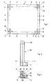
- Fig. 2 the starting cardboard is shown in a flat, square shape.
- the corner pieces 2 are still included.
- the visible outer edges, the corner parts 2 and the cutouts 27 for the inner walls of holding parts 13 of the corner parts 5 (FIG. 3) and 23 (FIG. 5) are expediently produced in a single punching process.
- bending edges 3 are also shown, around which edges 8 can be bent upwards by 90 °.
- Bending lines 25 are also shown, by which reinforcement parts 9 are rotated by 180 ° and glued to the inside of the edges 8.
- Two adjacent edge ends of the edges 8 are designated 6 and 7.
- the outside is expediently scored, provided with a groove or machined in another suitable manner.
- F ig. 2 shows a one-piece support column 20 with an upper insertion part 26 and lower ends 4, which can be attached over two adjacent edge ends 6 and 7 of two corresponding edges 8.
- Fig. 3 shows details of the lower end 4 of the support columns 20 according to a specific embodiment of the invention. Then in the middle of this end the cross section of the support column 20 can be seen, which corresponds to the upper end 26 of the support column 20, as can be seen in the front view of FIG. 2.
- the inner walls of the corner piece 5 are designated 18. At the ends of these inner walls 18, outward projections 10, 28 can be seen in use. In the operating state, these projections 28 interact with the reinforcements 9 of the rack insert mentioned above in order to form a stable but easily detachable connection. Such interaction between reinforcement 9 and projections 10, 28 (or projections 11 in FIG. 5) is always necessary if there is a tight fit or an elevation between corner piece 5 or 23 and the associated edge ends 6, 7 of the edges 8 should be dispensed with.
- a loose connection also requires the provision of base plates 14 and 15, which preferably consist of a single common plate (base plates 26 and 17 in the exemplary embodiment of FIG. 5). These base plates hold the shelf inserts in place. From Fig. 3 it can also be seen that the walls opposite the inner walls 18 are not as long as these. This helps save material and makes the corner pieces easier to handle.
- Fig. 4 details of the corners of Fig. 1 are shown on an enlarged scale.
- the edges 8, the edge ends 6 and 7 of these edges 8 and the reinforcing parts 9 can be seen.
- the preferred form of Recess 27 for the inner walls 18 and 19 of the corner pieces 5 and 23 with holding parts 13 can be seen.
- the reinforcements 9 are bent through 180 ° around the bending edges 25. The arrows are intended to illustrate this bending. Bending lines 3 are shown for the edges 8.
- Fig. 5 shows another embodiment for the ends of a support column. It can either be the end of a one-piece support column. 5, however, is intended to represent an independent corner piece 23 in cross section, which is in loose, removable engagement with edge ends 6 and 7 of two adjacent edges 8.
- the corner part 23 has holding parts 13 fastened to a circular sleeve and perpendicular to one another. These holding parts 13 consist of an incomplete U-shaped leg with a shorter (not designated) outer wall and an inner wall 19 which has an outwardly directed projection 11.
- the U-shaped legs are provided with base plates 16.
- a base plate 17 is preferably also provided between the two U-shaped legs and is expediently formed in one piece with the base plates 16 mentioned.
- the reinforcement 9 can also have the shape of a disk, for example made of plastic, from the outside of which projections of any kind, for example knobs, ribs or other patterns, protrude in the direction of the outer edges 6 and 7 of the shelf inserts. These projections can engage with corresponding recesses or openings on the opposite piece of the edge ends 6 and 7. Under certain circumstances, no cutouts are necessary at the edge ends 6 and 7, in this case the mechanical contact can also be made mechanically by pressing the projections into the edge ends 6 and 7. In this way, a simple and secure connection between edge ends 6 and 7 and Corner part 23 possible.
- a disk for example made of plastic
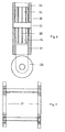
- Fig. 6 shows the structure of a three-part support column, for the special case of the lower end of the stackable shelf with a foot part.
- the corner piece 5 shown in detail in FIG. 5 is only indicated in FIG. 6.
- a coupling piece 22 is inserted, which has a wider diameter in the middle, which serves as a stop for the corner piece 23 and for an intermediate column 21.
- the tips 24 of this coupling piece are expediently tapered. In this way, the coupling parts can be connected very comfortably to the intermediate columns 21 or the corner pieces 23.
- the coupling pieces also have longitudinal ribs. This also serves for a better fit with easy assembly.
- a foot part in the form of a conventional roller 25 is inserted into the lower end of a shortened intermediate column 21 '. In this way, the stackable shelf can be moved comfortably.
- a roller 25 other ends, of course, such as a sleeve or a rubber plug can also be inserted.
- FIG. 8 shows an intermediate column 31 with a circular cross section, at the two ends of which coupling parts 32 are provided which are formed integrally with the intermediate column 31.
- These coupling parts 32 have a somewhat smaller cross section than the intermediate column 31, so that there is a stop when placed on the corner pieces 5, 23.
- FIG. 9a shows a coupling part in the form of an independent coupling piece 33.
- a coupling member 35 extends in one direction, from the opposite edge of the common bridge 34, a further coupling member 36 extends in the opposite direction tung.
- a coupling piece of this type makes it possible, for example, for the shelf arrangement according to FIG. 10 to be offset in height from one another, the outer columns comprising coupling pieces 22 according to FIG. 6 and the columns arranged therebetween having coupling pieces 33 according to FIG. 9a, the intermediate columns 21 and 21 'being long are different.
- FIG. 9b shows an antisymmetric coupling piece 37 with a common bridge 38, a single coupling member 39 extending symmetrically in the middle from one side of this coupling 38, whereas two further coupling members 40 extend from opposite edges of the other side of the common bridge 38 and 41 extend in a direction opposite to the direction of the coupling member 39.
- This coupling member is particularly well suited for a regular shelf installation shown in FIG. 11 with connection of adjacent shelves through a common column.
- the one length of the intermediate column with 21, the other length of the intermediate column with 21 ', the shelf inserts with 1, and the coupling pieces used on the outermost column with 22, the coupling pieces used between individual shelves with 33 are designated.
- the intermediate shelves have a different height than the outer shelves. In this way, the intermediate columns 21 'connect two adjacent shelves to one another.
- Fig. 11 is a symmetrical shelf arrangement using coupling pieces 37 according to Fig. 9b, where the same type of intermediate columns 21 can be used.
- Fig. 10 and in Fig. 11 are shown in the rest of the foot parts that a shortened intermediate column 21 " use, at the lower end stand parts 42 made of plastic or rubber are arranged.
- the invention creates an advantageous and versatile stackable shelf at astonishingly low cost.
Landscapes
- Life Sciences & Earth Sciences (AREA)
- Engineering & Computer Science (AREA)
- Wood Science & Technology (AREA)
- Assembled Shelves (AREA)
- Centrifugal Separators (AREA)
Priority Applications (1)
| Application Number | Priority Date | Filing Date | Title |
|---|---|---|---|
| AT80104510T ATE9863T1 (de) | 1979-08-10 | 1980-07-30 | Stapelbares regal. |
Applications Claiming Priority (2)
| Application Number | Priority Date | Filing Date | Title |
|---|---|---|---|
| DE2932550A DE2932550C2 (de) | 1979-08-10 | 1979-08-10 | Stapelbares Regal |
| DE2932550 | 1979-08-10 |
Publications (3)
| Publication Number | Publication Date |
|---|---|
| EP0024013A2 true EP0024013A2 (fr) | 1981-02-18 |
| EP0024013A3 EP0024013A3 (en) | 1981-09-09 |
| EP0024013B1 EP0024013B1 (fr) | 1984-10-17 |
Family
ID=6078203
Family Applications (1)
| Application Number | Title | Priority Date | Filing Date |
|---|---|---|---|
| EP80104510A Expired EP0024013B1 (fr) | 1979-08-10 | 1980-07-30 | Rayonnage superposable |
Country Status (3)
| Country | Link |
|---|---|
| EP (1) | EP0024013B1 (fr) |
| AT (1) | ATE9863T1 (fr) |
| DE (2) | DE2932550C2 (fr) |
Cited By (2)
| Publication number | Priority date | Publication date | Assignee | Title |
|---|---|---|---|---|
| DE3703641A1 (de) * | 1987-02-06 | 1988-08-18 | Miele & Cie | Traghalter fuer regalboeden, abstellborde oder dgl. |
| WO1994019989A3 (fr) * | 1993-02-23 | 1995-01-12 | Joachim Tillack | Rayonnage, systeme de rayonnage ou de cloisonnement |
Families Citing this family (1)
| Publication number | Priority date | Publication date | Assignee | Title |
|---|---|---|---|---|
| DE3420979A1 (de) * | 1984-06-06 | 1985-12-12 | Garreis Gmbh, 8941 Wolfertschwenden | Stapelbares tablett |
Family Cites Families (3)
| Publication number | Priority date | Publication date | Assignee | Title |
|---|---|---|---|---|
| CH406065A (de) * | 1963-12-27 | 1966-01-15 | Raetzer Viktor | Lagergestell |
| US3507399A (en) * | 1967-02-24 | 1970-04-21 | Jorge C Gruenberg | Shelf structure which may be quickly assembled or disassembled from standardized parts |
| DE2153603C3 (de) * | 1971-10-27 | 1981-02-26 | Franz Josef 6233 Kelkheim Lang | Etagenturm zur Warenausstellung |
-
1979
- 1979-08-10 DE DE2932550A patent/DE2932550C2/de not_active Expired
-
1980
- 1980-07-30 AT AT80104510T patent/ATE9863T1/de active
- 1980-07-30 DE DE8080104510T patent/DE3069458D1/de not_active Expired
- 1980-07-30 EP EP80104510A patent/EP0024013B1/fr not_active Expired
Cited By (2)
| Publication number | Priority date | Publication date | Assignee | Title |
|---|---|---|---|---|
| DE3703641A1 (de) * | 1987-02-06 | 1988-08-18 | Miele & Cie | Traghalter fuer regalboeden, abstellborde oder dgl. |
| WO1994019989A3 (fr) * | 1993-02-23 | 1995-01-12 | Joachim Tillack | Rayonnage, systeme de rayonnage ou de cloisonnement |
Also Published As
| Publication number | Publication date |
|---|---|
| ATE9863T1 (de) | 1984-11-15 |
| DE2932550A1 (de) | 1981-03-26 |
| EP0024013B1 (fr) | 1984-10-17 |
| DE2932550C2 (de) | 1982-02-04 |
| EP0024013A3 (en) | 1981-09-09 |
| DE3069458D1 (en) | 1984-11-22 |
Similar Documents
| Publication | Publication Date | Title |
|---|---|---|
| DE2813923A1 (de) | Stapelplattenartige konstruktion, insbesondere palette | |
| DE2915910A1 (de) | Regalteilersystem | |
| DE2451525C3 (de) | Verpackungsbehälter für Elektrogeräte oder ähnliche Artikel | |
| DE9000543U1 (de) | Zerlegbares Möbel, beispielsweise Regal | |
| EP0153426B1 (fr) | Rayonnage à assemblages d'angle emboîtables | |
| DE1586470A1 (de) | Zusammenklappbare Palettschachtel aus Wellkarton,impraegniertem Festkarton usw. | |
| DE3526259A1 (de) | Magazinpalette fuer rotationsteile | |
| EP0024013B1 (fr) | Rayonnage superposable | |
| DE3500064C2 (fr) | ||
| DE7711771U1 (de) | Bausatz fuer regale o.dgl. | |
| EP0357817B1 (fr) | Rayonnage en bois à insertion de tablettes à des niveaux variables | |
| DE7922957U1 (de) | Stapelbares regal | |
| DE3438685A1 (de) | Stapelbare schachtel, erzeugt aus einem blatt aus halbstarrem material | |
| EP0044355B1 (fr) | Présentoir et feuille de plastique découpée pour celui-ci | |
| DE8521190U1 (de) | Magazinpalette für Rotationsteile | |
| DE3516409C2 (fr) | ||
| DE19505193A1 (de) | Insbesondere im Bauwesen zu verwendende Vorrichtung zum Lagern oder Transportieren von Gerätschaften oder sonstigen Teilen | |
| DE8900344U1 (de) | Schalungseinsatz zum Herstellen einer Durchbrechung in einem Betonteil | |
| AT289636B (de) | Zusammenklappbare Palettschachtel | |
| DE2847191A1 (de) | Staender fuer saeulen- oder streifenfoermige gegenstaende sowie zuschnitt zur herstellung eines solchen staenders | |
| DE2818697C3 (de) | Spielzeug-Kaufladen | |
| DE2840426C2 (de) | Palette | |
| DE8405724U1 (de) | Regal mit steckbaren knotenpunktverbindungen | |
| DE1948247U (de) | Reklame- und schaustelleinrichtung. | |
| DE8329655U1 (de) | Plakatwand |
Legal Events
| Date | Code | Title | Description |
|---|---|---|---|
| PUAI | Public reference made under article 153(3) epc to a published international application that has entered the european phase |
Free format text: ORIGINAL CODE: 0009012 |
|
| AK | Designated contracting states |
Designated state(s): AT BE CH DE FR GB IT LU NL SE |
|
| PUAL | Search report despatched |
Free format text: ORIGINAL CODE: 0009013 |
|
| AK | Designated contracting states |
Designated state(s): AT BE CH DE FR GB IT LU NL SE |
|
| 17P | Request for examination filed |
Effective date: 19820211 |
|
| R17P | Request for examination filed (corrected) |
Effective date: 19820211 |
|
| ITF | It: translation for a ep patent filed | ||
| GRAA | (expected) grant |
Free format text: ORIGINAL CODE: 0009210 |
|
| AK | Designated contracting states |
Designated state(s): AT BE CH DE FR GB IT LI LU NL SE |
|
| PG25 | Lapsed in a contracting state [announced via postgrant information from national office to epo] |
Ref country code: NL Effective date: 19841017 Ref country code: BE Effective date: 19841017 |
|
| REF | Corresponds to: |
Ref document number: 9863 Country of ref document: AT Date of ref document: 19841115 Kind code of ref document: T |
|
| REF | Corresponds to: |
Ref document number: 3069458 Country of ref document: DE Date of ref document: 19841122 |
|
| ET | Fr: translation filed | ||
| NLV1 | Nl: lapsed or annulled due to failure to fulfill the requirements of art. 29p and 29m of the patents act | ||
| PG25 | Lapsed in a contracting state [announced via postgrant information from national office to epo] |
Ref country code: LU Free format text: LAPSE BECAUSE OF NON-PAYMENT OF DUE FEES Effective date: 19850731 |
|
| PGFP | Annual fee paid to national office [announced via postgrant information from national office to epo] |
Ref country code: AT Payment date: 19850731 Year of fee payment: 6 |
|
| PLBE | No opposition filed within time limit |
Free format text: ORIGINAL CODE: 0009261 |
|
| STAA | Information on the status of an ep patent application or granted ep patent |
Free format text: STATUS: NO OPPOSITION FILED WITHIN TIME LIMIT |
|
| 26N | No opposition filed | ||
| PG25 | Lapsed in a contracting state [announced via postgrant information from national office to epo] |
Ref country code: AT Effective date: 19860730 |
|
| PG25 | Lapsed in a contracting state [announced via postgrant information from national office to epo] |
Ref country code: SE Effective date: 19860731 Ref country code: LI Effective date: 19860731 Ref country code: CH Effective date: 19860731 |
|
| PG25 | Lapsed in a contracting state [announced via postgrant information from national office to epo] |
Ref country code: FR Free format text: LAPSE BECAUSE OF NON-PAYMENT OF DUE FEES Effective date: 19870331 |
|
| REG | Reference to a national code |
Ref country code: CH Ref legal event code: PL |
|
| PG25 | Lapsed in a contracting state [announced via postgrant information from national office to epo] |
Ref country code: DE Effective date: 19870401 |
|
| GBPC | Gb: european patent ceased through non-payment of renewal fee | ||
| REG | Reference to a national code |
Ref country code: FR Ref legal event code: ST |
|
| PG25 | Lapsed in a contracting state [announced via postgrant information from national office to epo] |
Ref country code: GB Effective date: 19881118 |
|
| EUG | Se: european patent has lapsed |
Ref document number: 80104510.5 Effective date: 19870518 |