EP0047859A2 - Système de mémoire à recirculation à deux vitesses - Google Patents
Système de mémoire à recirculation à deux vitesses Download PDFInfo
- Publication number
- EP0047859A2 EP0047859A2 EP81106230A EP81106230A EP0047859A2 EP 0047859 A2 EP0047859 A2 EP 0047859A2 EP 81106230 A EP81106230 A EP 81106230A EP 81106230 A EP81106230 A EP 81106230A EP 0047859 A2 EP0047859 A2 EP 0047859A2
- Authority
- EP
- European Patent Office
- Prior art keywords
- good
- memory
- address
- partially
- signal
- Prior art date
- Legal status (The legal status is an assumption and is not a legal conclusion. Google has not performed a legal analysis and makes no representation as to the accuracy of the status listed.)
- Granted
Links
Images


Classifications
-
- G—PHYSICS
- G11—INFORMATION STORAGE
- G11C—STATIC STORES
- G11C29/00—Checking stores for correct operation ; Subsequent repair; Testing stores during standby or offline operation
- G11C29/70—Masking faults in memories by using spares or by reconfiguring
- G11C29/86—Masking faults in memories by using spares or by reconfiguring in serial access memories, e.g. shift registers, CCDs, bubble memories
Definitions
- the present invention generally relates to memory systems utilizing memory components of the recirculating type which are operated selectively at fast and slow recirculating rates and, more particularly to such systems implemented with so called “partially good" memory components.
- Memory systems of the recirculating type for example of the charge coupled device (CCD) type, are well known.
- CCD charge coupled device
- This is made possible by the fact that the time phases of all the selected and non selected recirculating devices is known at all times. Therefore, access to a previously unselected device can be made promptly following completion of access to a selected device by keeping track of the known time phase of the recirculating bits of the former device upon completion of access to the latter device.
- the invention provides a solution to this problem.by using a two speed recirculating memory system utilizing partially-good components (chips) characterized,in principle, by permitting a second memory access promptly upon completing a first memory access in most cases and without requiring storage of data representing the locations of the defective portions of the partially-good components.
- the chips are sorted and mounted on memory array cards so that each card has mounted thereon sets of partially-good chips having defective portions in the same sectors as well as all-good chips having no defective portions.
- Translation logic is provided on each card whereby an address signal which corresponds to the address of a defective chip sector is translated to an address of an all-good chip.
- programmable means is mounted on each array card to allow sets of chips having defects in a different sector to be placed on different array cards whereby the same predetermined sector appears defective to the memory control system irrespective of which sectors actually are defective on the respective cards.
- Comparison means are provided in the memory control system to recognize each instance in which the predetermined sector is being addressed and, in those instances only, to generate a signal which selectively inhibits a second memory access which is begun prior to the completion of the "catch up" phase following a previous access.
- the inhibit signal preferably is applied to prevent an overlapping memory access in the case where the next access is to be made into a defective sector from a non-defective sector, or vice versa, of the same chip involved in the previous access.
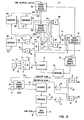
- Fig. 1 is a simplified block diagram of the memory system of the present invention. Only those features which are associated with the addressing and timing control of the memory arrays units are emphasized. State-of-the-art features not uniquely associated with the present invention are not shown for the sake of simplicity and clarity of exposition.
- the memory system comprises a system user 1 which is coupled via memory controller 2 to a plurality of memory components or memory array units 3, 4...N.
- the memory array units typically are large scale integration semiconductor chips containing memory elements of the recirculating type such as charge coupled device loops.
- Memory controller 2 comprises interface adapter 5, clocking source 6, memory synchronized 7 and address monitor 8.
- the interface adapter 5 receives control signals via bus 9 and data and address signals via bus 10 from system user 1 and, in turn, generates the appropriate select signals and other signals which are required for the reading, writing or data recirculating operations required by the memory array units.
- memory controller 2 provides the basic clock signals to allow the memory unit to be accessed at relatively fast clocking rates, to be placed into a power- saving standby mode at relatively low clocking rates, to accomplish resynchronization between accessed portions and non-accessed portions of the memory array unit following a memory access, and to permit the simultaneous resynchronization of previously accessed and non-accessed memory units while undertaking a subsequent access operation.
- Each of the memory array units 3, 4...N, in accordance with the present invention is implemented with partially-good large scale integration chips. After manufacture, the chips are tested and sorted in accordance with the location of the defective portions thereof. Chips having defective areas in the same physical location are mounted on the same mempry array unit card. For this purpose, it is convenient to subdivide the surface area of each chip into 8 portions, each portion being termed an octant. Chips having defects in the same octant are mounted on the same memory card.
- Each of the memory array units 3, 4...N receives address bits via bus 11 and A and B gating signals (to be described later) from memory synchronizer 7. Each memory array unit further receives a selector signal on line 12 at the output of address monitor 8 each time that the system user attempts to address a defective octant on one of the array cards. Data is transmitted between the memory array cards and interface adapter 5 via line 13. Finally, each of the array cards receives fast clocks and a masking signal via lines 14 and 15, respectively, from clocking source 6. The masking signals are gating signals coinciding with the slow clocks generated within source 6. Slow and fast clocks are applied to memory control and synchronizer 7 via lines 16 and 14.
- Memory synchronizer 7 and address monitor 8 of Fig. 1 are represented by the simplified block diagram of Fig. 2.
- the memory synchronizer receives an address from interface adapter 5 which address is loaded into pending address register 90.
- the address is read out of register 90 thru register 100 and is transmitted via bus 11 to the memory array units 3, 4...N for selection of the memory unit.
- the addressing scheme is shown in Fig. 3.
- 6 of the bits of the address located in registers 90 and 100 represented by bits A, B and C and bits X, Y and Z are utilized in addressing the memory array units. Bits A, B and C select the chip rows whereas bits X, Y and Z represent the octant of the chips being addressed within the memory array units.
- bits A, B and C are substituted for bits X, Y and Z in the case where a defective octant is being addressed within the partially-good chips comprising the memory array units.
- the octant addressing bits X, Y and Z are permutated, if necessary, in order that the defective octants of all the chips in any given memory array unit is addressed when each of the bits X, Y and Z is a binary one. This will be discussed in connection with Fig. 5 to be described later.
- the address read out of register 100 also is applied to microprocessor controller 18 which computes an address representing the position of the recirculating bits within each of the address chips at a predetermined future time when access is to be made for reading or writing purposes.
- the position of the recirculating bits of the address chip is represented by the count in counter 19 which is selectively driven either by the slow clocks or by the fast clocks applied via line 20 at the output of AND-OR gates 21.
- Counter 19, like the addressed recirculating loop is driven by slow clock pulses during the time that the recirculating loop is in the standby or low power mode.
- Counter 19, like the addressed recirculating loop is driven by fast clock pulses during the time that the recirculating loop is operating in the access mode for reading or writing purposes.
- a signal indicating that access is to be made is provided by interface adapter 5 of Fig. 1 via line 22 to clocking source 6.
- Clocking source 6 provides the access signal as well as the slow and fast clocks by lines 23, 16 and 14 to the memory synchronizer shown in Fig. 2.
- the access signal is directly applied to AND gate 25 of gate 21 and by means of inverter 26 to AND gate 27. Accordingly, the fast clock pulses are applied via gates 25 to line 20 during the select mode while the slow clock pulses are applied by gate 27 to line 20 during the remainder of the time.
- the address computed by microprocessor 18 is stored within counter 50 and is compared within comparator 28 with the count in counter 19 to provide a "start clock" signal on line 29 when the two counts are equal.
- the signal on line 29 is jointly applied to counter 30 and to AND gates 31 and 45.
- Counter 30 is preset to a count equalling the number of bits to be transferred during the accessing of the addressed memory loop.
- the count in counter 30 is decremented at the fast clock rate until the count reduces to zero indicating that the desired data transfer has been completed.
- a "start catch up" signal is generated on line 32 indicating that the data transfer has been completed and is applied jointly to counter 33, inverter 34 and AND gate 39.
- the output from inverter 34 is applied to a second input to AND gate 31.
- AND gate 31 also receives the 9 signal on line 99 signifying that a defective octant is not being addressed.
- AND gate 31 is conditioned by the 9 signal to conduct to produce the A gate signal on line 35 during the interval between the initiation of signals from comparator 28 and from counter 30, respectively, i.e., during the time of the data transfer.
- the recirculating memory components comprising array units 3, 4...N are driven by slow clock pulses during the standby mode in order to conserve power and to minimize corresponding heat dissipation problems.
- the memory components are driven by. high frequency clock pulses, during the time that they are being accessed, to reduce accessing time. Accordingly, upon the completion of accessing to an addressed memory component, the previously unaccessed memory components are out of synchronization with the addressed components. In order to restore synchronization between the accessed and the unaccessed components, the previously accessed component continues to be driven by the fast clock pulses until such time that it "catches up" to (or overtakes) the unaccessed components which continue to be driven by the slow clock pulses.
- Counter 33 begins counting from zero immediately upon the completion of a previous memory access.
- the count in counter 33 is compared in comparator 36 with the count in counter 37.
- Counter 37 is driven by the slow clock pulses of line 16 so that the count in counter 37 represents the position of the recirculating bits in the unaccessed memory components.
- the count in counter 33 represents the position of the recirculating bits in the previously accessed memory components which is now continuing to be driven by the fast clock pulses in order to achieve "catch up”.
- the counts in counters 33 and 37 become equal when synchronization is restored between the previously accessed memory components and the previously unaccessed memory components and produces a "stop catch up" signal on line 38 representing that condition.
- a gate a gating signal on line 35
- B gate a gating signal on line 40
- all rows of the all-good chips are driven at the same fast clock rate if any row is selected or at the same slow clock rate if no row is selected.
- the time phase between the recirculating bits of an accessed memory component and the recirculating bits of an unaccessed recirculating component depends upon whether the recirculating bits of the unaccessed components are within the good portion or within the defective portion of the partially-good chip containing both portions. This is true because an all-good chip is substituted for a partially-good chip whenever a defective portion of a partially-good chip is being addressed.
- each of the array units may contain chips having defective portions in different octants, it normally would be necessary to store in memory the locations of these defective portions for each of the memory units in order that resynchronization can be achieved between the accessed and unaccessed components independent of which card is being addressed at a given time.
- This problem is avoided, in accordance with the present invention, by the technique of making the addresses of the defective portions of all of the partially-good components appear to be the same standard address to the system user.
- a signal is generated which selectively inhibits the next memory fetch until after resynchronization has been achieved between the last accessed and the unaccessed memory components. Such inhibition occurs only in the case where the next memory access is to be made into a defective octant from a non defective octant, or vice versa, of the same memory chip involved in the last proceedinging memory access. The next access is permitted to occur immediately following completion of the preceding access in all other cases.
- next memory fetch is inhibited by directing microprocessor controller 18 to delay the transfer of the pending address from register 90 into the current address register 100 until "catch up" has been completed. In the absence of the inhibit signal, the next memory fetch begins upon completion of the current data transfer.
- AND gate 45 also receives the "start clock” signal on line 29 coinciding with the initiation of the A gate.
- AND gate 46 also receives the B "stop catch up” signal on line 38.
- the outputs of gates 45 and 46 are applied to OR circuit 47 which, in turn, produces a select signal S on output line 12.
- the S signal is applied directly to AND gate 104, and via inverter 105, to AND gate 106.
- the X, Y and Z bits of the pending address in register 90 are compared (comparator 42) against a set of all binary "one" bits on line 43 to produce a signal on line 44 which is directly applied to AND gate 106 and, via inverter 107, to AND gate 104.
- A, B, and C bits (representing chip address) from the pending and the current addresses in registers 90 and 100, respectively, are compared (comparator 108) to provide a signal on line 109.
- the signal on line 109 which is "active" if the compared chip addresses are the same, is applied jointly to AND gates 106 and 104. It will be seen that AND gate 106 performs the function described in row I of the truth table of Fig. 4 while AND gate 104 performs the function of row II to provide an inhibit signal on line 120 at the output of OR circuit 111 which receives its inputs from AND circuits 106 and 104.
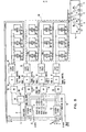
- the clock timing control for the memory array units of Fig. 1 is shown in Fig. 5 along with chip address translation logic.
- certain state-of-the-art details associated with data bussing and chip addressing including the substitution of a row of all-good chips in the event that a defective row of the partially-good chips is addressed, have been omitted.
- Such details are well known in the prior art as exemplified, for example, in the aforementioned US patent 3 845 476.
- Bits A, B and C from data bus 11 of Figs. 1 and 2 are applied simultaneously to row decoder latches 51 and 52 and to the all-good chips 53.
- the A gate signal on line 35 and the B gate signal on line 40 are applied to decoder latches 51 and 52, respectively.
- the A, B and C bits are latched up and then decoded in block 51 to apply a clock pulse gating signal to line 54 for the duration of the A gate signal in the event that row 1 of the partially-good chips of the memory array portion 55 is being addressed.
- the A, B and C bits are latched up and decoded in block 52 to produce a signal on line 56 during the occurence of the B gate signal in the event that row 1 of memory array portion 55 is being addressed.
- Signals corresponding to those of lines 54 and 56 are produced on lines 57 and 58 in the event that row 2 of memory array portion 55 is being addressed. The same is true with respect to the signals produced on lines 59 and 60.
- the signals on lines 54 and 56 are applied to OR circuit 61 along with the mask signal of line 15.
- the resulting output signal on line 62 is applied to row 1 AND gate 63 of memory array portion 55.
- the signals on lines 57 and 58 are ORed (circuit 64) and applied to row 2 AND gate 65 while the signals on lines 59 and 60 are ORed (circuit 66) and applied to row 8 AND gate 67.
- Gates 65 and 67 also receive the mask signal of line 15 via their respective OR circuits 64 and 66.
- Eight rows are illustrated in memory array portion 55 by way of example only, consistent with the three row selection bits A, B and C of bus 11 of the disclosed embodiment.
- Each of the row AND gates 63, 65 and 67, as well as the AND gate 68 associated with the all-good chips 53 of the memory array also receive the fast clocking signals of line 14.
- the select signal, S, of line 12 indicating that a defective row portion of the partially-good chips is being addressed, is directed to OR circuit 70 along with the mask signals of line 15 and are then applied to AND gate 68 of the all-good chip row.
- AND gates 63, 65 and 67 are rendered conductive only at the slow clocking rate in the event that a defective portion is being addressed inasmuch as neither the A nor B gate signal appears at OR circuits 61, 64 and 66 in that case.
- the octant selection signals for addressing the partially-good chips of memory array portion 55 are represented by the X, Y and Z signals on the respective lines of bus 11.
- Each of the X, Y and Z bit signals are inverted by complementing circuits (not shown) to provide the X, Y and Z signals applied to contacts 71, 72 and 73, respectively, of switches 74.
- the X, Y and Z signals are directed to the respective contacts 75, 76 and 77.
- the contacting arms 78, 79 and 80 are individually positioned so that the defective portions of the partially-good chips are addressed by predetermined bit values, say, 111, for bits X, Y and Z.
- the chips comprising memory array portion 55 are tested, sorted and mounted so that the defective portion exists in the same chip areas for all chips mounted on a common memory array card.
- row 1 AND gate 63 passes fast clocking pulses to the row 1 clock driver 81 (if bits A, B and C designate row 1) during the time of the A gate signal and during the time of the B gate signal in the event that a defective octant is not being addressed by the X, Y and Z signals.
- the addressing of a defective octant causes the select signal of line 12 (applied by OR circuit 70) to condition AND gate 68 to pass the fast clocking pulses to driver 82 of the all-good chip row.
- All of the bit rows of chips 53 are clocked at the same fast clocking rate during the time that a defective octant of the partially-good chips of array portion 55 is being addressed. However, only the addressed row of the chips within array portion 55 is clocked at a fast rate while A gate and B gate signals are present on lines 35 and 40, respectively.
- the unselected rows of the chips comprising memory array portion 55 are driven at a slow clocking rate inasmuch as row selection signals (of lines 54, 56, 57, 58, 59 and 60) are not applied to the OR circuits (61, 64 and 66) of the unselected rows. In such a case, the OR circuit for the unselected rows receives only the mask signal of line 15 which recurs at the slow clocking rate as previously stated.
- the row AND gates (such as AND gate 63, 65 and 67) of the unselected rows are conditioned to pass only those fast clocks of line 14 which coincide with the mask signals on line 15 which are subharmonically related to the fast clock of line 14 at the slow clocking rate.
Landscapes
- Techniques For Improving Reliability Of Storages (AREA)
- Hardware Redundancy (AREA)
- Shift Register Type Memory (AREA)
Applications Claiming Priority (2)
| Application Number | Priority Date | Filing Date | Title |
|---|---|---|---|
| US06/187,254 US4365318A (en) | 1980-09-15 | 1980-09-15 | Two speed recirculating memory system using partially good components |
| US187254 | 1994-01-25 |
Publications (3)
| Publication Number | Publication Date |
|---|---|
| EP0047859A2 true EP0047859A2 (fr) | 1982-03-24 |
| EP0047859A3 EP0047859A3 (en) | 1984-12-05 |
| EP0047859B1 EP0047859B1 (fr) | 1988-06-01 |
Family
ID=22688225
Family Applications (1)
| Application Number | Title | Priority Date | Filing Date |
|---|---|---|---|
| EP81106230A Expired EP0047859B1 (fr) | 1980-09-15 | 1981-08-10 | Système de mémoire à recirculation à deux vitesses |
Country Status (4)
| Country | Link |
|---|---|
| US (1) | US4365318A (fr) |
| EP (1) | EP0047859B1 (fr) |
| JP (1) | JPS5853438B2 (fr) |
| DE (1) | DE3176769D1 (fr) |
Cited By (6)
| Publication number | Priority date | Publication date | Assignee | Title |
|---|---|---|---|---|
| GB2135485A (en) * | 1983-01-21 | 1984-08-30 | Hitachi Ltd | Semiconductor memory device |
| FR2564620A1 (fr) * | 1984-05-16 | 1985-11-22 | Philips Nv | Systeme a fonctionnement numerique serie-parallele-serie |
| EP0096781A3 (en) * | 1982-06-16 | 1986-12-17 | International Business Machines Corporation | System for updating error map of fault tolerant memory |
| EP0096780A3 (en) * | 1982-06-16 | 1986-12-30 | International Business Machines Corporation | A fault alignment exclusion method to prevent realignment of previously paired memory defects |
| EP0096782A3 (en) * | 1982-06-16 | 1986-12-30 | International Business Machines Corporation | Online realignment of memory faults |
| EP0096779A3 (en) * | 1982-06-16 | 1986-12-30 | International Business Machines Corporation | Multi-bit error scattering arrangement to provide fault tolerant semiconductor memory |
Families Citing this family (12)
| Publication number | Priority date | Publication date | Assignee | Title |
|---|---|---|---|---|
| US4736373A (en) * | 1981-08-03 | 1988-04-05 | Pacific Western Systems, Inc. | Memory tester having concurrent failure data readout and memory repair analysis |
| US4521874A (en) * | 1982-09-28 | 1985-06-04 | Trw Inc. | Random access memory device |
| DE69024086T2 (de) | 1989-04-13 | 1996-06-20 | Sundisk Corp | EEprom-System mit Blocklöschung |
| US5051994A (en) * | 1989-04-28 | 1991-09-24 | International Business Machines Corporation | Computer memory module |
| US5123107A (en) * | 1989-06-20 | 1992-06-16 | Mensch Jr William D | Topography of CMOS microcomputer integrated circuit chip including core processor and memory, priority, and I/O interface circuitry coupled thereto |
| JP2941308B2 (ja) | 1989-07-12 | 1999-08-25 | 株式会社日立製作所 | 検査システムおよび電子デバイスの製造方法 |
| US6185324B1 (en) * | 1989-07-12 | 2001-02-06 | Hitachi, Ltd. | Semiconductor failure analysis system |
| KR0121800B1 (ko) * | 1992-05-08 | 1997-11-22 | 사또오 후미오 | 메모리 카드장치 |
| US5668763A (en) * | 1996-02-26 | 1997-09-16 | Fujitsu Limited | Semiconductor memory for increasing the number of half good memories by selecting and using good memory blocks |
| US5923682A (en) * | 1997-01-29 | 1999-07-13 | Micron Technology, Inc. | Error correction chip for memory applications |
| DE59810778D1 (de) * | 1997-09-18 | 2004-03-25 | Infineon Technologies Ag | Anordnung mit einem Umlaufspeicher und mit eine Einrichtung, welche ein auf den Umlaufspeicher zugreifendes Programm ausführt |
| US6067633A (en) * | 1998-03-31 | 2000-05-23 | International Business Machines Corp | Design and methodology for manufacturing data processing systems having multiple processors |
Family Cites Families (8)
| Publication number | Priority date | Publication date | Assignee | Title |
|---|---|---|---|---|
| US3654610A (en) * | 1970-09-28 | 1972-04-04 | Fairchild Camera Instr Co | Use of faulty storage circuits by position coding |
| US3765001A (en) * | 1970-09-30 | 1973-10-09 | Ibm | Address translation logic which permits a monolithic memory to utilize defective storage cells |
| US3781826A (en) * | 1971-11-15 | 1973-12-25 | Ibm | Monolithic memory utilizing defective storage cells |
| US3755791A (en) * | 1972-06-01 | 1973-08-28 | Ibm | Memory system with temporary or permanent substitution of cells for defective cells |
| US3845476A (en) * | 1972-12-29 | 1974-10-29 | Ibm | Monolithic memory using partially defective chips |
| US3976179A (en) * | 1974-12-30 | 1976-08-24 | Texaco Inc. | Controlling the temperature of a depropanizer tower by chromatographic analysis of feed and bottoms |
| US4066880A (en) * | 1976-03-30 | 1978-01-03 | Engineered Systems, Inc. | System for pretesting electronic memory locations and automatically identifying faulty memory sections |
| JPS52124826A (en) * | 1976-04-12 | 1977-10-20 | Fujitsu Ltd | Memory unit |
-
1980
- 1980-09-15 US US06/187,254 patent/US4365318A/en not_active Expired - Lifetime
-
1981
- 1981-07-20 JP JP56112394A patent/JPS5853438B2/ja not_active Expired
- 1981-08-10 EP EP81106230A patent/EP0047859B1/fr not_active Expired
- 1981-08-10 DE DE8181106230T patent/DE3176769D1/de not_active Expired
Non-Patent Citations (2)
| Title |
|---|
| IBM TECHNICAL DISCLOSURE BULLETIN, vol. 22, no. 1, June 1979, pages 138-139, New York, US; F.J. AICHELMANN Jr.: "Multiplexed partial-good chip scheme employing defective loops as selectors for all-good chips" * |
| IBM TECHNICAL DISCLOSURE BULLETIN, vol. 23, no. 1, June 1980, pages 194-195, New York, US; F.J. AICHELMANN Jr. et al.: "CCD loop synchronization catch-up scheme" * |
Cited By (7)
| Publication number | Priority date | Publication date | Assignee | Title |
|---|---|---|---|---|
| EP0096781A3 (en) * | 1982-06-16 | 1986-12-17 | International Business Machines Corporation | System for updating error map of fault tolerant memory |
| EP0096780A3 (en) * | 1982-06-16 | 1986-12-30 | International Business Machines Corporation | A fault alignment exclusion method to prevent realignment of previously paired memory defects |
| EP0096782A3 (en) * | 1982-06-16 | 1986-12-30 | International Business Machines Corporation | Online realignment of memory faults |
| EP0096779A3 (en) * | 1982-06-16 | 1986-12-30 | International Business Machines Corporation | Multi-bit error scattering arrangement to provide fault tolerant semiconductor memory |
| GB2135485A (en) * | 1983-01-21 | 1984-08-30 | Hitachi Ltd | Semiconductor memory device |
| US4656610A (en) * | 1983-01-21 | 1987-04-07 | Hitachi, Ltd. | Semiconductor memory device having redundancy means |
| FR2564620A1 (fr) * | 1984-05-16 | 1985-11-22 | Philips Nv | Systeme a fonctionnement numerique serie-parallele-serie |
Also Published As
| Publication number | Publication date |
|---|---|
| JPS5755596A (en) | 1982-04-02 |
| US4365318A (en) | 1982-12-21 |
| EP0047859A3 (en) | 1984-12-05 |
| EP0047859B1 (fr) | 1988-06-01 |
| JPS5853438B2 (ja) | 1983-11-29 |
| DE3176769D1 (en) | 1988-07-07 |
Similar Documents
| Publication | Publication Date | Title |
|---|---|---|
| US4365318A (en) | Two speed recirculating memory system using partially good components | |
| US4319356A (en) | Self-correcting memory system | |
| US6111814A (en) | Synchronous DRAM memory with asynchronous column decode | |
| US6000022A (en) | Method and apparatus for coupling signals between two circuits operating in different clock domains | |
| US4734880A (en) | Dynamic random access memory arrangements having WE, RAS, and CAS derived from a single system clock | |
| AU1437192A (en) | Refresh control arrangement for dynamic random access memory system | |
| US3997882A (en) | Content addressable memory system employing charge coupled device storage and directory registers and N/(1-H) counter refresh synchronization | |
| JP3226425B2 (ja) | 半導体記憶装置 | |
| US5291580A (en) | High performance burst read data transfer operation | |
| US5202857A (en) | System for generating memory timing and reducing memory access time | |
| US6292867B1 (en) | Data processing system | |
| JPH06131253A (ja) | メモリワードの管理回路 | |
| US5623648A (en) | Controller for initiating insertion of wait states on a signal bus | |
| US7181643B2 (en) | Method for comparing the address of a memory access with an already known address of a faulty memory cell | |
| JPH05189296A (ja) | 単一のビットメモリに対する同時書き込みアクセス装置 | |
| US5045999A (en) | Multi-function timing sequencer for different speed main storage units | |
| JPH05282859A (ja) | メモリ集積回路 | |
| JP2783495B2 (ja) | クロック乗せ換え回路 | |
| JPS586478A (ja) | パタ−ン発生器 | |
| JPH0624908Y2 (ja) | デ−タ転送制御装置 | |
| JPH04259984A (ja) | メモリアクセス方法 | |
| JPH0467661B2 (fr) | ||
| JPH0241058B2 (fr) | ||
| JPH09311811A (ja) | シングルポートram2方向アクセス回路 | |
| JPH04145382A (ja) | メモリ内蔵型半導体集積回路 |
Legal Events
| Date | Code | Title | Description |
|---|---|---|---|
| PUAI | Public reference made under article 153(3) epc to a published international application that has entered the european phase |
Free format text: ORIGINAL CODE: 0009012 |
|
| 17P | Request for examination filed |
Effective date: 19810810 |
|
| AK | Designated contracting states |
Designated state(s): DE FR GB |
|
| PUAL | Search report despatched |
Free format text: ORIGINAL CODE: 0009013 |
|
| AK | Designated contracting states |
Designated state(s): DE FR GB |
|
| 17Q | First examination report despatched |
Effective date: 19860127 |
|
| GRAA | (expected) grant |
Free format text: ORIGINAL CODE: 0009210 |
|
| AK | Designated contracting states |
Kind code of ref document: B1 Designated state(s): DE FR GB |
|
| REF | Corresponds to: |
Ref document number: 3176769 Country of ref document: DE Date of ref document: 19880707 |
|
| R20 | Corrections of a patent specification |
Effective date: 19880711 |
|
| ET | Fr: translation filed | ||
| PLBE | No opposition filed within time limit |
Free format text: ORIGINAL CODE: 0009261 |
|
| 26N | No opposition filed | ||
| PGFP | Annual fee paid to national office [announced via postgrant information from national office to epo] |
Ref country code: GB Payment date: 19910717 Year of fee payment: 11 |
|
| PGFP | Annual fee paid to national office [announced via postgrant information from national office to epo] |
Ref country code: FR Payment date: 19910726 Year of fee payment: 11 |
|
| PGFP | Annual fee paid to national office [announced via postgrant information from national office to epo] |
Ref country code: DE Payment date: 19910828 Year of fee payment: 11 |
|
| PG25 | Lapsed in a contracting state [announced via postgrant information from national office to epo] |
Ref country code: GB Effective date: 19920810 |
|
| GBPC | Gb: european patent ceased through non-payment of renewal fee |
Effective date: 19920810 |
|
| PG25 | Lapsed in a contracting state [announced via postgrant information from national office to epo] |
Ref country code: FR Effective date: 19930430 |
|
| PG25 | Lapsed in a contracting state [announced via postgrant information from national office to epo] |
Ref country code: DE Effective date: 19930501 |
|
| REG | Reference to a national code |
Ref country code: FR Ref legal event code: ST |