EP0073041B1 - Verfahren und Einrichtung zur Herstelling von magnetischen Aufzeichnungsträgern - Google Patents
Verfahren und Einrichtung zur Herstelling von magnetischen Aufzeichnungsträgern Download PDFInfo
- Publication number
- EP0073041B1 EP0073041B1 EP82107650A EP82107650A EP0073041B1 EP 0073041 B1 EP0073041 B1 EP 0073041B1 EP 82107650 A EP82107650 A EP 82107650A EP 82107650 A EP82107650 A EP 82107650A EP 0073041 B1 EP0073041 B1 EP 0073041B1
- Authority
- EP
- European Patent Office
- Prior art keywords
- gas
- vapor
- base body
- edge region
- mask
- Prior art date
- Legal status (The legal status is an assumption and is not a legal conclusion. Google has not performed a legal analysis and makes no representation as to the accuracy of the status listed.)
- Expired
Links
- 230000005291 magnetic effect Effects 0.000 title claims description 74
- 238000000034 method Methods 0.000 title claims description 31
- 238000004519 manufacturing process Methods 0.000 title claims description 10
- 239000007789 gas Substances 0.000 claims description 57
- 238000000151 deposition Methods 0.000 claims description 25
- QVGXLLKOCUKJST-UHFFFAOYSA-N atomic oxygen Chemical compound [O] QVGXLLKOCUKJST-UHFFFAOYSA-N 0.000 claims description 20
- 230000008021 deposition Effects 0.000 claims description 20
- 239000001301 oxygen Substances 0.000 claims description 20
- 229910052760 oxygen Inorganic materials 0.000 claims description 20
- 238000001816 cooling Methods 0.000 claims description 8
- 239000003302 ferromagnetic material Substances 0.000 claims description 8
- 230000005294 ferromagnetic effect Effects 0.000 claims description 7
- 239000007921 spray Substances 0.000 claims description 3
- 230000000903 blocking effect Effects 0.000 claims description 2
- 239000010410 layer Substances 0.000 description 60
- 239000010408 film Substances 0.000 description 35
- -1 polyethylene terephthalate Polymers 0.000 description 14
- 229920000139 polyethylene terephthalate Polymers 0.000 description 14
- 239000005020 polyethylene terephthalate Substances 0.000 description 14
- 229910045601 alloy Inorganic materials 0.000 description 13
- 239000000956 alloy Substances 0.000 description 13
- 239000000463 material Substances 0.000 description 12
- 239000000758 substrate Substances 0.000 description 12
- 238000010894 electron beam technology Methods 0.000 description 10
- 229910020630 Co Ni Inorganic materials 0.000 description 9
- 229910002440 Co–Ni Inorganic materials 0.000 description 9
- 238000010438 heat treatment Methods 0.000 description 9
- XKRFYHLGVUSROY-UHFFFAOYSA-N Argon Chemical compound [Ar] XKRFYHLGVUSROY-UHFFFAOYSA-N 0.000 description 8
- 230000008859 change Effects 0.000 description 7
- 230000000694 effects Effects 0.000 description 6
- 239000003507 refrigerant Substances 0.000 description 6
- 230000007246 mechanism Effects 0.000 description 5
- XEEYBQQBJWHFJM-UHFFFAOYSA-N Iron Chemical compound [Fe] XEEYBQQBJWHFJM-UHFFFAOYSA-N 0.000 description 4
- 229910052786 argon Inorganic materials 0.000 description 4
- 238000007796 conventional method Methods 0.000 description 4
- 238000005070 sampling Methods 0.000 description 4
- 238000009792 diffusion process Methods 0.000 description 3
- 229910052759 nickel Inorganic materials 0.000 description 3
- 238000005192 partition Methods 0.000 description 3
- RYGMFSIKBFXOCR-UHFFFAOYSA-N Copper Chemical compound [Cu] RYGMFSIKBFXOCR-UHFFFAOYSA-N 0.000 description 2
- 229910020516 Co—V Inorganic materials 0.000 description 2
- 229910020515 Co—W Inorganic materials 0.000 description 2
- MYMOFIZGZYHOMD-UHFFFAOYSA-N Dioxygen Chemical compound O=O MYMOFIZGZYHOMD-UHFFFAOYSA-N 0.000 description 2
- UQSXHKLRYXJYBZ-UHFFFAOYSA-N Iron oxide Chemical compound [Fe]=O UQSXHKLRYXJYBZ-UHFFFAOYSA-N 0.000 description 2
- 229910000990 Ni alloy Inorganic materials 0.000 description 2
- 239000004952 Polyamide Substances 0.000 description 2
- 239000011230 binding agent Substances 0.000 description 2
- 230000015572 biosynthetic process Effects 0.000 description 2
- 229910052802 copper Inorganic materials 0.000 description 2
- 239000010949 copper Substances 0.000 description 2
- 238000005260 corrosion Methods 0.000 description 2
- 230000007797 corrosion Effects 0.000 description 2
- 229910001882 dioxygen Inorganic materials 0.000 description 2
- 230000004907 flux Effects 0.000 description 2
- 238000007733 ion plating Methods 0.000 description 2
- 229910052742 iron Inorganic materials 0.000 description 2
- 238000002844 melting Methods 0.000 description 2
- 239000002245 particle Substances 0.000 description 2
- FPVKHBSQESCIEP-JQCXWYLXSA-N pentostatin Chemical compound C1[C@H](O)[C@@H](CO)O[C@H]1N1C(N=CNC[C@H]2O)=C2N=C1 FPVKHBSQESCIEP-JQCXWYLXSA-N 0.000 description 2
- 229920002647 polyamide Polymers 0.000 description 2
- 229920001721 polyimide Polymers 0.000 description 2
- 230000008569 process Effects 0.000 description 2
- 230000005855 radiation Effects 0.000 description 2
- 239000010409 thin film Substances 0.000 description 2
- 238000007740 vapor deposition Methods 0.000 description 2
- 229910020598 Co Fe Inorganic materials 0.000 description 1
- 229910020632 Co Mn Inorganic materials 0.000 description 1
- 229910002519 Co-Fe Inorganic materials 0.000 description 1
- 229910020678 Co—Mn Inorganic materials 0.000 description 1
- 229910020707 Co—Pt Inorganic materials 0.000 description 1
- 229910020705 Co—Rh Inorganic materials 0.000 description 1
- 229910020711 Co—Si Inorganic materials 0.000 description 1
- 229910020517 Co—Ti Inorganic materials 0.000 description 1
- 229910000599 Cr alloy Inorganic materials 0.000 description 1
- 229910018487 Ni—Cr Inorganic materials 0.000 description 1
- 238000005299 abrasion Methods 0.000 description 1
- 239000003990 capacitor Substances 0.000 description 1
- 239000011248 coating agent Substances 0.000 description 1
- 238000000576 coating method Methods 0.000 description 1
- 239000000470 constituent Substances 0.000 description 1
- 239000000498 cooling water Substances 0.000 description 1
- 239000013078 crystal Substances 0.000 description 1
- 230000003247 decreasing effect Effects 0.000 description 1
- 238000011161 development Methods 0.000 description 1
- 238000009826 distribution Methods 0.000 description 1
- 230000008020 evaporation Effects 0.000 description 1
- 238000001704 evaporation Methods 0.000 description 1
- 239000008235 industrial water Substances 0.000 description 1
- 239000011261 inert gas Substances 0.000 description 1
- 230000008018 melting Effects 0.000 description 1
- 239000002184 metal Substances 0.000 description 1
- 229910052751 metal Inorganic materials 0.000 description 1
- 239000002923 metal particle Substances 0.000 description 1
- 238000013021 overheating Methods 0.000 description 1
- 230000002035 prolonged effect Effects 0.000 description 1
- 238000009751 slip forming Methods 0.000 description 1
- 239000010935 stainless steel Substances 0.000 description 1
- 229910001220 stainless steel Inorganic materials 0.000 description 1
- 239000002344 surface layer Substances 0.000 description 1
- 238000012360 testing method Methods 0.000 description 1
- 238000001771 vacuum deposition Methods 0.000 description 1
Images

Classifications
-
- G—PHYSICS
- G11—INFORMATION STORAGE
- G11B—INFORMATION STORAGE BASED ON RELATIVE MOVEMENT BETWEEN RECORD CARRIER AND TRANSDUCER
- G11B5/00—Recording by magnetisation or demagnetisation of a record carrier; Reproducing by magnetic means; Record carriers therefor
- G11B5/84—Processes or apparatus specially adapted for manufacturing record carriers
- G11B5/851—Coating a support with a magnetic layer by sputtering
-
- H—ELECTRICITY
- H01—ELECTRIC ELEMENTS
- H01F—MAGNETS; INDUCTANCES; TRANSFORMERS; SELECTION OF MATERIALS FOR THEIR MAGNETIC PROPERTIES
- H01F41/00—Apparatus or processes specially adapted for manufacturing or assembling magnets, inductances or transformers; Apparatus or processes specially adapted for manufacturing materials characterised by their magnetic properties
- H01F41/14—Apparatus or processes specially adapted for manufacturing or assembling magnets, inductances or transformers; Apparatus or processes specially adapted for manufacturing materials characterised by their magnetic properties for applying magnetic films to substrates
- H01F41/20—Apparatus or processes specially adapted for manufacturing or assembling magnets, inductances or transformers; Apparatus or processes specially adapted for manufacturing materials characterised by their magnetic properties for applying magnetic films to substrates by evaporation
Definitions
- the present invention relates to a method for manufacturing a magnetic recording medium, comprising the steps of depositing a ferromagnetic material on a polymeric base body which is moved along a cooling support body in a vacuum chamber including a vapor source emitting vapor of said ferromagnetic material, wherein the vapor beam is emitted by said source in the direction of the cooling support body and an incident angle control mask is inserted between the source and said support body for blocking a part of said beam so as to define a boundary angle of the part of the beam hitting the base body, and a device for carrying through this method.
- a vapor deposition device and method using a mask is known.
- a gaseous stream is directed towards the mask in order to cool the mask.
- the gas used during evaporation can be chosen such as to impart certain properties to the deposited film.
- a vapor deposition device wherein a gaseous stream is led along a mask in order to transport the magnetic vapor towards the substrate with a preferred angle of incidence.
- the coercive force of the magnetic recording medium has been increased to satisfy the needs for high density recording.
- For recording and reproducing high-frequency signals only the surface layer is magnetized. An output cannot be sufficiently increased by only an increase in coercive force.
- a material which has a high saturation density of magnetic fluxes has received attention to increase the high-frequency signal output.
- a typical example is a medium containing a nonmagnetic material such as a binder based on the conventional coating. In this medium, ferromagnetic metal particles such as iron particles or alloy particles which have substantially a high saturation density of magnetic fluxes are used instead of iron oxide.
- Another example is a medium including a thin metal ferromagnetic film as a magnetic recording layer, which does not use a binder. Since the thin film is formed by vacuum deposition, the medium is called a "deposition tape". It is partially commercially available.
- the deposition tape has been recently developed and is still in a developing stage, so that there are many problems to be solved so as to realize wider industrial applications.
- a basical problem is a matter of coercive force control. Stable control of the coercive force is a significant issue in the technical development. of the deposition tape.
- An oblique deposition method disclosed in Japanese Laid-Open Patent Application No. 41-19389 is capable of stably controlling the coercive force.
- a gas is sprayed from the edge region of said incident angle control mask, said edge region defining the beginning of the part of the beam hitting the base body, and furthermore the gas is sprayed from said edge region in such a direction that the deposition of the blocked ferromagnetic vapor in the edge region is prevented.
- the incident angle of the vapor beam cannot be changed by deposition of ferromagnetic vapor on the edge region of the control mask and that part of the beam which should hit the base body is kept highly constant resulting into a highly reliable magnetic recording medium of uniform quality.
- the present invention relates also to a device for manufacturing a magnetic recording medium, comprising a support body for cooling and supporting a polymeric base body which is being moved therealong, a vapor source for depositing a ferromagnetic material on said polymeric base body which is being moved along said support body, and an incident angle control mask for controlling an angle of incidence of a vapor flow from said vapor source to said polymeric base body.
- gas spray nozzles are formed in the edge region of said incident angle control mask, said edge region defining the beginning of the part of the beam hitting the base body.
- Fig. 1 shows a deposition device used in the present invention.
- the deposition device is divided into two chambers.
- an elongated substrate 1 is supplied from a supply reel 11 to take-up reel 12 through a rotary can 4 along the direction indicated by arrow R.
- Other members such as a free roller and an expander which are included in the take-up mechanism are not illustrated. However, these members are included in the take-up mechanism as needed.
- the rotary can 4 supports and cools the substrate 1.
- the rotary can 4 may be replaced by a cooled endless belt.
- a vapor source disposed to oppose the rotary can 4 is of the type known to those who are skilled in the art. However, the vapor source is preferably heated by an electron beam.
- a model representing a vapor source container 3 and a vapor material 2 is illustrated in Fig. 1. Note that an electron beam source is not shown in the figure.
- a vacuum chamber 5 is subdivided into an upper compartment 6 and a lower compartment 7.
- Reference numeral 13 denotes a partition plate.
- a gas is exhausted from the upper and lower compartments 6 and 7 through exhaust systems 10 and 9 respectively which are generally independent of each other.
- Reference numeral 8 denotes a mask for controlling an angle or incidence.
- the angle of incidence is defined as 8 1 formed by a normal to a point D and a line SD which is an extended line of a line SPo connecting a center S of the vapor source and an end Po of the mask and which reaches the point D on the surface of the substrate (around the outer surface of the can).
- the mask 8 is arranged so that a gas is sprayed in the vicinity of the end Po.
- the magnetic vapor therefore, may not be deposited in the vicinity of the end Po of the mask 8.
- the angle of incidence 6 1 which is determined by the line SPo with respect to the elongated substrate 1 can be kept constant.
- the shape of the mask may be of part of an arc or of a combination of linear structures.
- the gas is preferably flowed into the chamber in accordance with known flow rate and pressure control techniques, the type of gas may be selected from an active gas, an inert gas and a mixed gas.
- a polyethylene terephthalate film of 10.5 pm thickness and 500 mm width was used as a base body at an angle of incidence 8 1 of 70°.
- a layer of Co.Ni alloy (Co: 80%; Ni 20%) was formed on the polyethylene terephthalate to a thickness of 0.1 ⁇ m.
- the pressure of the lower compartment was 2,66 ⁇ 10- 3 Pa (2x10 -5 Torr).
- the coercive force of the magnetic layer obtained was 835,8 A/cm (1050 Oe).
- the squareness ratio was 0.96.
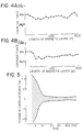
- Magnetic film I was formed in an atmosphere of argon (Ar) gas supplied at a flow rate of 0.1 I/min (1 kg/cm 2 ) according to the method of the present invention, whereas magnetic film II was formed without using a gas according to a conventional method. Results are shown in Fig. 2, in which sampling was performed along the longitudinal direction of the substrate, and the coercive force distribution is indicated by error bars in the transverse direction.
- a magnetic layer of 100% Co was formed on a polyethylene terephthalate film of 15 pm thickness and 500 mm width to a thickness of 0.2 pm at an angle of incidence 8 1 of 73°.
- the overall length of the deposited magnetic layer in an atmosphere of argon with a flow rate of 0.1 I/min (1 kg/cm 2 ) was 2,050 m.
- the pressure in the lower compartment was 2,266 - 10- 3 Pa (1.7x 10 -5 Torr).
- the coercive force was 955,2 A/cm (1,200 Oe) at 0 m, 1,000 m and 2,000 m.
- the squareness ratio was 0.97.
- a magnetic layer of a Co-Cr alloy (Co: 85%; Cr: 15%) was formed on a polyethylene terephthalate film of 11.5 um thickness and 500 mm width at an angle of incidence 8 1 of 60° and at a pressure of 1,333 10 -3 Pa (1x10 -5 Torr).
- the coercive force at the initial portion of the layer and a portion of 1,000 m was 780,08 A/cm (980 Oe).
- the squareness ratio was 0.98.
- the magnetic layers were uniform in the transverse direction thereof.
- the coercive force of the magnetic layer formed with the Ar flow rate of 0.05 I/min is slightly changed as compared with that with the Ar flow rate of 0.2 I/min.
- the coercive force of the magnetic layer slightly depends on the flow rate of the gas. Therefore, the flow rate required in formation of the magentic layer is preferably optimized by adjusting the diameter of the nozzles and the distance between the adjacent nozzles.
- a magnetic layer of a CO-Ni alloy (CO: 80%; Ni: 20%) was formed on a polyamide film of 8.5 ⁇ m thickness to a thickness of 0.15 ⁇ m at an angle of incidence ⁇ of 45°.
- Oxygen was supplied to the lower compartment through the vicinity of the end of the mask.
- the flow rate of oxygen was 0.22 I/min (1 kg/cm 2 ).
- the deposition pressure was 5,999 10-3Pa (4.5x10- 5 Torr).
- the coercive force was 732,32 A/cm (920 Oe), and the squareness ratio was 0.88.
- the magnetic layer was uniform over the length of 4,000 m in the longitudinal and transverse directions.
- the coercive force is increased by about 15% at a portion at 1,000 m, and 34% at 2,000 m.
- the film supply speed must be decreased by 40% or the power of the electron beams must be increased by 30% in order to control the thickness of the deposited layer.
- the preset conditions can be stably maintained, the deposited film thickness can be controlled, unlike the conventional method.
- the effects of the present invention have been confirmed by ion plating using a high frequency signal of 13.56 MHz with high frequency electrodes disposed between the film and the vapor source. Further, a vapor material such as Fe, Co-V, Co-W, Co-Mn, Co-Ti, Co-Si, Co-Ni-Cr and Co-Pt was used to obtain the same effects obtained in the above examples of the present invention.
- a gas such as N 2 , C0 2 and CO was used to confirm the effects of the present invention.
- the method of the present invention is very effective regardless of the mechanism (e.g., crystal magnetic anisotropy, shape anisotropy, and distortion) of generating the coercive force.
- the mechanism e.g., crystal magnetic anisotropy, shape anisotropy, and distortion
- a method for forming an oxide film on the surface of the ferromagnetic layer to improve corrosion-resistance of the magnetic recording medium will be described. Since this method does not use an additional material as is used in the conventional method, stability and reliability of the magnetic recording medium are greatly improved.
- a magnetic layer is continuously formed on a base body which has a width of more than 50 cm, and the base body with the magnetic layer is cut into strips of a predetermined width. It is necessary to control the thickness of the oxide layer in both the longitudinal and transverse directions of the base body, in order to achieve a uniform quality of the oxide film.
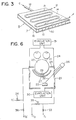
- a mask as shown in Fig. 3 is used for this purpose.
- the mask 8 has a jacket structure which has a rear surface 14 (viewed from the vapor source), a front surface 16, a side surface 17, another side surface (not shown) opposite the side surface 17, a side surface 20 and another side surface (not shown) opposite the side surface 20.
- a copper pipe 19 is soldered onto the rear surface 14. Cooling water W flows through the copper pipe 19 so as to prevent overheating.
- a gas G is introduced from a gas pipe 18 and is sprayed from a number of nozzles 15 formed in the side surface 20.
- a partition plate may be inserted inside the jacket, as needed, to uniformly spray the gas from the nozzles 15.
- the shape of the jacket may be optimized hydrodynamically so that the effect of the present invention can be further emphasized.
- the gas may be sufficiently controlled by a known technique.
- a polyethylene terephthalate film of 10.5 ⁇ m thickness was wound at a speed of 25 m/min. Simultaneously, 100% Co was vaporized by electron beam heating to form a magnetic layer of 0.15 ⁇ m thickness on the polyethylene terephthalate film in an oxygen atmosphere, while oxygen was supplied at a flow rate of 0.035 I/min and at a pressure of 1.5 kg/cm 2.
- the temperature of the rotary can was controlled by maintaining a circulating refrigerant at a temperature of -3°C.
- Sampling was performed at 12 points along the transverse direction of the magnetic layer and 10 points along the longitudinal direction thereof to examine the magnetic characteristics, the thickness and quality, and the resistances to corrosion and wear of the oxide layer. Variation in the coercive force and the squareness ratio was within ⁇ 5%. The variation in thickness of the oxide film was ⁇ 8%. The quality of the oxide film at the above-mentioned points was uniform. Further, when the oxide film thus manufactured was placed over 8 weeks in an atmosphere having a relative humidity of 85% at a temperature of 60°C, there was no change at all.
- a polyethylene terephthalate film of 12.5 um thickness was wound at a speed of 30 m/min.
- a vapor material of a Co-Ni alloy (Co: 85%, and Ni: 15%) was vaporized by electron beam heating.
- Oxygen was supplied at a flow rate of 0.03 I/min and at a pressure of 2 kg/cm 2 to obtain a magnetic layer of 0.13 pm thickness.
- the temperature of the circulating refrigerant of the rotary can was 0°C.
- Example 5 The same sampling test as in Example 5 was performed. The variation in the coercive force and the squareness ratio of the magnetic layer were ⁇ 5%. The variation in the thickness of the oxide layer was ⁇ 7%. A uniform quality oxide layer was obtained. Further, the magnetic layer did not corrode over 9 weeks at a temperature of 60°C and at a relative humidity of 95%.
- a magnetic layer of a Co-Ni alloy (Co: 75; and Ni: 25%) was formed on a polyimide film of 25 um thickness to a thickness of 0.2 ⁇ m while the polyimide film was fed at a speed of 30 m/min and oxygen was supplied at a flow rate of 0.1 I/min (1 kg/cm 2 ).
- the variation in the coercive force and the squareness ratio of the magnetic layer were ⁇ 6%, and the variation in the thickness of the oxide layer was ⁇ 6%.
- the quality of the oxide layer was substantially the same as that obtained in the previous examples.
- the magnetic layer did not corrode over 9 weeks at a temperature of 60°C and at a relative humidity of 95%.
- Magnetic layers of a Co-Ni alloy (Co: 80%; and Ni; 20%), a Co-Ni alloy (Co: 70%; and Ni: 30%), a Co-Fe alloy (Co: 50%; and Fe: 50%), a Co-Rh alloy (Co: 95%; and Rh: 5%), and a Co-V alloy (Co: 95%; and V: 5%) were respectively formed on polyethylene terephthalate films of 12 pm thickness up to a thickness of 0.06 ⁇ m at an oxygen flow rate of 0.02 to 0.15 I/min.
- the quality of the magnetic layers was substantially the same as that in Examples 5 to 7.
- An endless belt (60 cm in width and 2 m in length) of SUS 304 (0.6 t) was used in place of the rotary can as the cooling support.
- a polymeric base body was conveyed on the endless belt to form a magnetic layer thereon. The same effects were obtained as when the rotary can was used.
- a high frequency coil (2 turns) which had a diameter of 60 cm was disposed substantially between the rotary can and the vapor source.
- Magnetic layers of a Co-Ni alloy (Co: 80%, and Ni: 20%), a Co-W alloy (Co: 95%; and W: 5%), and Co (100%) were respectively formed to a thickness of 0.1 pm on polyethylene terephthalate films each of which had a width of 50 cm, at an angle of incidence of more than 15° and at an oxygen flow rate of 0.015 I/min.
- the films were fed at a speed of 15 m/min.
- the high frequency-power was 450 W, and the frequency was 13.56 MHz.
- the obtained magnetic layer was of substantially the same quality as those in the previous examples.
- a Co-Ni alloy (Co: 90%; and Ni: 10%) was vaporized by electron beam heating while a polyethylene terephthalate film of 9.5 ⁇ m thickness was being wound at a speed of 35 m/min and oxygen was supplied at a flow rate of 0.4 I/min and at a pressure of 1 kg/cm 2.
- a magnetic layer of 0.16 um thickness was obtained.
- the variation in the magnetic characteristics of the magnetic layer was ⁇ 4%.
- the variation in the thickness of the oxide layer was ⁇ 6%.
- the quality of the oxide layer was uniform.
- the magnetic layer did not corrode over 10 weeks at a temperature of 60°C and at a relative humidity of 95%. Thus, a highly reliable magnetic layer was obtained.
- a Co-Ni alloy (Co: 83% and Ni: 17%) was vaporized by electron beam heating, and a magnetic layer of 0.2 pm thickness was deposited on a polyamide film of 8 ⁇ m thickness which was being wound at a speed of 25 m/min at an oxygen flow rate of 0.1 I/min (2.1 kg/cm 2 ). Thereafter, the surface of the magnetic layer was exposed to glow discharge (glow discharge conditions: 500 V and 77 A) in an oxygen atmosphere at a pressure of 0,1333 102 Pa (0.1 Torr) for 2.5 sec. The variation in the magnetic characteristics was ⁇ 5.5%, and the variation in the thickness of the oxygen layer was ⁇ 5.5%. Further, a uniform quality oxide layer was obtained. The magnetic film did not corrode over 17 weeks at a temperature of 60°C and at a relative humidity of 95%. A highly reliable magnetic layer was obtained.
- the effect of the present invention can be found when the length of the deposited magnetic layer is more than 1,000 m.
- the output stability of ⁇ 0.2 dB can be given at a length of 2,000 m of the deposited magnetic layer.
- the output stability of ⁇ 0.23 dB can be given at a length of 3,000 m of the deposited magnetic layer. Further, the output stability of ⁇ 0.2 dB can be given at a length of 4,000 m.
- a process has conventionally been performed in which a substrate is continuously moved to form a thin film thereon while a gas is supplied to a vacuum chamber.
- a gas is supplied to a vacuum chamber.
- the scale of deposition using a gas is small. Therefore, if such deposition is performed for an elongated substrate, unknown problems may be presented.
- the take-up deposition devices have been widely used in the fields of laminate boards and electric components such as capacitors.
- the production quantity is several tens of thousand meters per batch.
- the deposition materials are limited to low-melting point materials such as AI and Zn.
- problems are encountered when the substrate is elongated.
- control methods for supplying a gas There are two control methods for supplying a gas: one method is for controlling the flow rate of the gas; and another method is for controlling the pressure of the gas. It is important to control the gas supply with high precision by these methods. It is, however, difficult to control the characteristics of the magnetic tape by these methods, as is shown in Figs. 4A and 4B.
- Fig. 4A shows a change in the coercive force as a function of the length of the deposited layer when a polyethylene terephthalate film of 9.5 pm thickness is moved at a speed of 30 m/min along the rotary can which has a diameter of 1 m and a temperature of 20°C, while oxygen is supplied at a flow rate of 0.35 ⁇ 0.01 I/min, and when Co is deposited on the polyethylene terephthalate film at an angle of incidence which is greater than 40°.
- Fig. 4A shows a change in the coercive force as a function of the length of the deposited layer when a polyethylene terephthalate film of 9.5 pm thickness is moved at a speed of 30 m/min along the rotary can which has a diameter of 1 m and a temperature of 20°C, while oxygen is supplied at a flow rate of 0.35 ⁇ 0.01 I/min, and when Co is deposited on the polyethylene terephthalate film at an angle of incidence which is greater than 40°.
- 4B shows a change in coercive force when Co is deposited on the polyethylene terephthalate film in the same manner as described above, while oxygen is supplied in a vacuum chamber which is kept at a pressure of 4,666 10 -3 Pa (3.5x10 -5 Torr ( ⁇ 5%)).
- the sum Q' should be suitably smaller than the amount Q so as to optimize the manufacturing cost as far as is consistent with satisfying the required precision and quality.
- a vacuum P eq of a base material portion which is close to the deposition area is given by the following relation: where Q v is the amount of exhaust gas (Torr I/sec), S v is the exacuation rate of gas with respect to the exhaust gas (I/sec), Q, is the amount of leakage air (Torr I/sec), S is the evacuation rate of gas with respect to the leakage air (I/sec), and P o is the pressure of the pump.
- Q v is the amount of exhaust gas (Torr I/sec)
- S v the exacuation rate of gas with respect to the exhaust gas (I/sec)
- Q is the amount of leakage air (Torr I/sec)
- S is the evacuation rate of gas with respect to the leakage air (I/sec)
- P o is the pressure of the pump.
- Co and Co-Ni (Co: 80%; and Ni: 20%) are respectively deposited over a length of 10,000 m to a thickness of 0.1 pm to obtain deposited films by changing the ratio of Q to Q'.
- the coercive forces of these deposited films are examined, and the results are shown in Fig. 5.
- method (4) and a combination of methods (3) and (4) are most suitable in consideration of economy.
- FIG. 6 shows a device which practices the method of the present invention.
- a vacuum chamber wall 25 receives radiation energy radiated from a vapor source 22 when the vapor source 22 is kept at a high temperature and has a jacket structure. Inside the jacket, a medium at a certain temperature can be circulated. Valves 33 and 34 are opened, while valves 35 and 36 are closed. The heating medium is then circulated. Thereafter, the valves 33 and 34 are closed and the valves 35 and 36 are opened. Then, the refrigerant is circulated.
- a vacuum chamber 24 is subdivided into upper and lower compartments by a partition wall 29.
- a take-up mechanism and an electrical discharge mechanism are arranged in the upper compartment.
- the vapor source 22, a vapor material supply unit, a shutter 27 and a mask 28 are arranged in the lower compartment.
- the rotary support body 23 is disposed so as to move a polymeric base body therealong.
- the rotary support body 23 need not be a can in which a medium at a proper temperature is circulated.
- the rotary support body 23 may thus comprise an endless belt at a proper temperature.
- Reference numerals 30 and 31 denote evacuation units.
- Reference numeral 26 illustratively denotes an electron beam generator for giving energy to the vapor source 22.
- the parts to be arranged in a jacket structure are parts, excluding the vacuum chamber wall 25, which receive radiation energy from the vapor source. Therefore, the shutter 27 and the mask 28 preferably have a jacket structure.
- the medium circulating paths may be series-connected or connected in a combination of paths connected in parallel to and in series with each other, as needed.
- the outer dimensions of the rectangular vacuum chamber are 2 m in width, 2 m in height, and 1 m in depth.
- a cylindrical can which has a diameter of 85 cm is disposed substantially at the center of the vacuum chamber.
- the outer wall of the lower compartment has a jacket structure.
- the mask and the shutter have the same structure as the outer wall of the lower compartment.
- An oil diffusion pump of 36,000 I/sec is disposed in the lower compartment, whereas an oil diffusion ejector pump of 4,000 I/sec is disposed in the upper chamber.
- Co-Ni alloys (Ni: 10%, 20% and 25%, respectively) are vaporized by electron beam heating, and oxygen is supplied to the vacuum chamber at a pressure of 6,666 . 10 -3 to 9,33 ⁇ 10-3 Pa (5x10 -5 to 7x10 -5 Torr). Magnetic layers of 0.13 ⁇ m thickness are respectively deposited on polyethylene terephthalate films of 9.5 pm thickness. At this time, Q is 15,998 - 10 2 Pa I/sec (12 Torr I/sec). Each base body, of an overall length of 5,000 m and a width of 500 mm with the deposited magnetic layer thereon,-is cut into magnetic tapes each of which has a width of 1/2" (12.7 mm). The magnetic characteristics of the magnetic tape are examined.
- the atmospheric gas is evacuated from the vacuum chamber, and the heating medium at a temperature of 160°C is simultaneously circulated in the outer wall, the mask and the shutter so as to set the vacuum chamber at a pressure of 1,333 10-2 Pa (1x 10- 4 Torr).
- the electron beams are radiated onto the vapor material to preliminarily melt it.
- the vapor material is preheated.
- a refrigerant at a temperature of 0°C is supplied to the vacuum chamber, this case being defined as case A.
- case B is defined as case B in which a refrigerant at a temperature of 20°C is supplied to the vacuum chamber.
- Still another case is defined as case C in which industrial water (temperature: 20°C to 25°C) is circulated without circulating the heating medium beforehand.
- the coercive forces of the tapes are measured for cases A, B, and C.
- the figures show changes in the coercive force of an area of 50 m having the given tape position as its center.
- the gas containing at least oxygen is sprayed so as to direct a vapor flow toward the base body through the vicinity of the incident angle control portion of the mask, and the supply conditions of the gas are properly determined.
- Highly reliable magnetic media can be mass-produced.
- a novel recording medium for satisfying the needs of short wavelength magnetic recording can be abundantly supplied.
Landscapes
- Engineering & Computer Science (AREA)
- Power Engineering (AREA)
- Manufacturing & Machinery (AREA)
- Manufacturing Of Magnetic Record Carriers (AREA)
- Physical Vapour Deposition (AREA)
Claims (4)
Applications Claiming Priority (6)
| Application Number | Priority Date | Filing Date | Title |
|---|---|---|---|
| JP56131176A JPS5832234A (ja) | 1981-08-20 | 1981-08-20 | 磁気記録媒体の製造方法 |
| JP131176/81 | 1981-08-20 | ||
| JP142698/81 | 1981-09-09 | ||
| JP56142698A JPS5845625A (ja) | 1981-09-09 | 1981-09-09 | 磁気記録媒体の製造方法 |
| JP161624/81 | 1981-10-09 | ||
| JP56161624A JPS5864375A (ja) | 1981-10-09 | 1981-10-09 | 真空蒸着法 |
Publications (3)
| Publication Number | Publication Date |
|---|---|
| EP0073041A2 EP0073041A2 (de) | 1983-03-02 |
| EP0073041A3 EP0073041A3 (en) | 1985-03-13 |
| EP0073041B1 true EP0073041B1 (de) | 1988-03-16 |
Family
ID=27316261
Family Applications (1)
| Application Number | Title | Priority Date | Filing Date |
|---|---|---|---|
| EP82107650A Expired EP0073041B1 (de) | 1981-08-20 | 1982-08-20 | Verfahren und Einrichtung zur Herstelling von magnetischen Aufzeichnungsträgern |
Country Status (3)
| Country | Link |
|---|---|
| US (1) | US4450186A (de) |
| EP (1) | EP0073041B1 (de) |
| DE (2) | DE73041T1 (de) |
Families Citing this family (17)
| Publication number | Priority date | Publication date | Assignee | Title |
|---|---|---|---|---|
| JPS5961014A (ja) * | 1982-09-29 | 1984-04-07 | Fuji Photo Film Co Ltd | 磁気記録媒体 |
| JPS5961013A (ja) * | 1982-09-29 | 1984-04-07 | Fuji Photo Film Co Ltd | 磁気記録媒体 |
| JPS5968815A (ja) * | 1982-10-12 | 1984-04-18 | Sony Corp | 磁気記録媒体 |
| US4478174A (en) * | 1983-02-25 | 1984-10-23 | Canadian Patents & Development Limited | Vacuum coating vessel with movable shutter plate |
| JPS59160828A (ja) * | 1983-03-01 | 1984-09-11 | Fuji Photo Film Co Ltd | 磁気記録媒体 |
| JPS59165244A (ja) * | 1983-03-08 | 1984-09-18 | Fuji Photo Film Co Ltd | 磁気記録媒体の製造装置 |
| JPS59203238A (ja) * | 1983-04-30 | 1984-11-17 | Tdk Corp | 磁気記録媒体の製造方法 |
| US4575475A (en) * | 1983-07-12 | 1986-03-11 | Tdk Corporation | Magnetic recording medium |
| US4592923A (en) * | 1983-10-24 | 1986-06-03 | Sharp Kabushiki Kaisha | Production method of a high magnetic permeability film |
| DE3573672D1 (en) * | 1984-01-26 | 1989-11-16 | Hitachi Maxell | Magnetic recording medium and production thereof |
| DE3565694D1 (en) * | 1984-02-02 | 1988-11-24 | Hitachi Metals Ltd | Process for manufacturing magnetic recording media |
| JPS6139234A (ja) * | 1984-07-30 | 1986-02-25 | Fuji Photo Film Co Ltd | 薄膜形成装置 |
| JPH0610856B2 (ja) * | 1984-08-04 | 1994-02-09 | ティーディーケイ株式会社 | 磁気記録媒体 |
| US4713262A (en) * | 1984-08-14 | 1987-12-15 | Fuji Photo Film Co., Ltd. | Manufacturing method for a magnetic recording medium |
| JPH083902B2 (ja) * | 1988-02-17 | 1996-01-17 | 富士写真フイルム株式会社 | 薄膜型磁気記録媒体の製造方法 |
| DE4207525C2 (de) * | 1992-03-10 | 1999-12-16 | Leybold Ag | Hochvakuum-Beschichtungsanlage |
| KR100239102B1 (ko) * | 1993-10-20 | 2000-01-15 | 모리시타 요이찌 | 자기기록매체의 제조방법 |
Family Cites Families (3)
| Publication number | Priority date | Publication date | Assignee | Title |
|---|---|---|---|---|
| DE907322C (de) * | 1944-12-07 | 1954-03-25 | Hydrawerk Ag | Verfahren zur Metallbedampfung eines Dielektrikums, insbesondere zur Herstellung von Belagschichten fuer elektrische Kondensatoren |
| US3394678A (en) * | 1966-12-23 | 1968-07-30 | Air Reduction | Apparatus for vacuum coating |
| GB1596385A (en) * | 1976-12-29 | 1981-08-26 | Matsushita Electric Industrial Co Ltd | Methods and apparatus for manufacturing magnetic recording media |
-
1982
- 1982-08-19 US US06/409,608 patent/US4450186A/en not_active Expired - Lifetime
- 1982-08-20 EP EP82107650A patent/EP0073041B1/de not_active Expired
- 1982-08-20 DE DE198282107650T patent/DE73041T1/de active Pending
- 1982-08-20 DE DE8282107650T patent/DE3278257D1/de not_active Expired
Also Published As
| Publication number | Publication date |
|---|---|
| EP0073041A2 (de) | 1983-03-02 |
| US4450186A (en) | 1984-05-22 |
| EP0073041A3 (en) | 1985-03-13 |
| DE3278257D1 (en) | 1988-04-21 |
| DE73041T1 (de) | 1984-01-05 |
Similar Documents
| Publication | Publication Date | Title |
|---|---|---|
| EP0073041B1 (de) | Verfahren und Einrichtung zur Herstelling von magnetischen Aufzeichnungsträgern | |
| EP0053811B1 (de) | Magnetische Aufzeichnungsmedien | |
| US4661418A (en) | Magnetic recording medium | |
| US4767516A (en) | Method for making magnetic recording media | |
| US4511594A (en) | System of manufacturing magnetic recording media | |
| JPS5961105A (ja) | 磁気記録媒体 | |
| US4673610A (en) | Magnetic recording medium having iron nitride recording layer | |
| US4521481A (en) | Magnetic recording medium | |
| US4343834A (en) | Process for preparing magnetic recording medium | |
| US5679166A (en) | Magnetic recording media, magnetic recording media fabrication method, and fabrication equipment | |
| KR0185237B1 (ko) | 자기기록매체 및 그 제조방법 | |
| EP0617414B1 (de) | Verfahren und Vorrichtung zur Herstellung eines magnetischen Aufzeichnungsträgers | |
| US5908711A (en) | Magnetic recording medium | |
| JPH0546013B2 (de) | ||
| US6021964A (en) | Gas introduction pipe and magnetic recording medium production method using the pipe | |
| US4526131A (en) | Magnetic recording medium manufacturing apparatus | |
| US5736263A (en) | Magnetic recording medium comprising successive magnetic metallic films of iron, nickel, and cobalt deposited on a substrate | |
| EP0688016A2 (de) | Methode und Vorrichtung zur Herstellung eines magnetischen Aufzeichnungsmediums | |
| JPH033118A (ja) | 磁気記録媒体の製造方法 | |
| JPS59178626A (ja) | 磁気記録媒体の製法 | |
| JPH061540B2 (ja) | 磁気記録媒体 | |
| JPH0969438A (ja) | 磁気記録媒体 | |
| JPH1079120A (ja) | 磁気記録媒体の製造方法 | |
| JPS63251935A (ja) | 磁気記録媒体の製造方法 | |
| JPH04291016A (ja) | 磁気記録媒体およびその製造方法 |
Legal Events
| Date | Code | Title | Description |
|---|---|---|---|
| PUAI | Public reference made under article 153(3) epc to a published international application that has entered the european phase |
Free format text: ORIGINAL CODE: 0009012 |
|
| AK | Designated contracting states |
Designated state(s): DE FR GB |
|
| EL | Fr: translation of claims filed | ||
| DET | De: translation of patent claims | ||
| PUAL | Search report despatched |
Free format text: ORIGINAL CODE: 0009013 |
|
| AK | Designated contracting states |
Designated state(s): DE FR GB |
|
| 17P | Request for examination filed |
Effective date: 19850521 |
|
| 17Q | First examination report despatched |
Effective date: 19860916 |
|
| GRAA | (expected) grant |
Free format text: ORIGINAL CODE: 0009210 |
|
| AK | Designated contracting states |
Kind code of ref document: B1 Designated state(s): DE FR GB |
|
| REF | Corresponds to: |
Ref document number: 3278257 Country of ref document: DE Date of ref document: 19880421 |
|
| ET | Fr: translation filed | ||
| PLBE | No opposition filed within time limit |
Free format text: ORIGINAL CODE: 0009261 |
|
| STAA | Information on the status of an ep patent application or granted ep patent |
Free format text: STATUS: NO OPPOSITION FILED WITHIN TIME LIMIT |
|
| 26N | No opposition filed | ||
| PGFP | Annual fee paid to national office [announced via postgrant information from national office to epo] |
Ref country code: GB Payment date: 19950809 Year of fee payment: 14 Ref country code: FR Payment date: 19950809 Year of fee payment: 14 |
|
| PGFP | Annual fee paid to national office [announced via postgrant information from national office to epo] |
Ref country code: DE Payment date: 19950828 Year of fee payment: 14 |
|
| PG25 | Lapsed in a contracting state [announced via postgrant information from national office to epo] |
Ref country code: GB Effective date: 19960820 |
|
| GBPC | Gb: european patent ceased through non-payment of renewal fee |
Effective date: 19960820 |
|
| PG25 | Lapsed in a contracting state [announced via postgrant information from national office to epo] |
Ref country code: FR Effective date: 19970430 |
|
| PG25 | Lapsed in a contracting state [announced via postgrant information from national office to epo] |
Ref country code: DE Effective date: 19970501 |
|
| REG | Reference to a national code |
Ref country code: FR Ref legal event code: ST |