EP0080904B1 - Mehrstellungssteuergerät - Google Patents
Mehrstellungssteuergerät Download PDFInfo
- Publication number
- EP0080904B1 EP0080904B1 EP82306408A EP82306408A EP0080904B1 EP 0080904 B1 EP0080904 B1 EP 0080904B1 EP 82306408 A EP82306408 A EP 82306408A EP 82306408 A EP82306408 A EP 82306408A EP 0080904 B1 EP0080904 B1 EP 0080904B1
- Authority
- EP
- European Patent Office
- Prior art keywords
- counter
- switching
- switching means
- signal
- predetermined positions
- Prior art date
- Legal status (The legal status is an assumption and is not a legal conclusion. Google has not performed a legal analysis and makes no representation as to the accuracy of the status listed.)
- Expired
Links
- 238000010586 diagram Methods 0.000 description 3
- 238000010276 construction Methods 0.000 description 1
- 238000001514 detection method Methods 0.000 description 1
Images
Classifications
-
- G—PHYSICS
- G05—CONTROLLING; REGULATING
- G05D—SYSTEMS FOR CONTROLLING OR REGULATING NON-ELECTRIC VARIABLES
- G05D3/00—Control of position or direction
- G05D3/12—Control of position or direction using feedback
- G05D3/20—Control of position or direction using feedback using a digital comparing device
-
- G—PHYSICS
- G05—CONTROLLING; REGULATING
- G05D—SYSTEMS FOR CONTROLLING OR REGULATING NON-ELECTRIC VARIABLES
- G05D3/00—Control of position or direction
Definitions
- the present invention relates to a multi-position controller for controlling the position of an object.
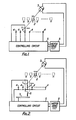
- the conventional position controller includes a movable contact 1, an object 2 to be controlled, a motor 3, fixed contacts 4, a controlling circuit 5 and a motor driving circuit 8.
- the movable contact 1 is mechanically coupled to the object 2, which in turn is arranged to be driven by the motor 3. More specifically, when the motor rotates, the position of the object moves from a to b. c. d.... n. At these positions, respectively corresponding fixed contacts 4 are arranged to be connected to the movable contact 1.
- the controlling circuit 5 outputs a control signal to the motor driving circuit 8 to cause the motor 3 to rotate so as to move the object to the position a.
- the motor is stopped.
- the motor has to be first rotated in either direction for the movable contact to be connected to one of the fixed contacts before the above described movement of the object to position a can be achieved.
- the number of fixed contacts and connecting lines between the fixed contacts and the controlling circuit must correspond to the number of such multiple positions between which the object is to be moved. Further, when such multiple positions are increased in number, the number of fixed contacts, connecting lines and input terminals of the controlling circuit must be increased likewise.
- German patent specification DE-A-1,125,520 discloses a configuration similar to that described above in relation to Fig. 1.
- the present invention provides a multiposition controller for moving an object to a desired one of a plurality of predetermined positions, comprising a drive means for driving said object, a first switching means arranged to provide a switching signal in response to movement of said object between said predetermined positions, and a control means responsive to said switching signal for producing a control signal for controlling said drive means, characterised by said first switching means having a single output line for supplying said control means with said switching signal, and by a second switching means which changes its on/off state when said object moves from one side to the other of a datum position which is one of the plurality of predetermined positions, said second switching means being connected to said control means so that said control means, on receipt of a command to move said object to said desired one of said predetermined positions, initially controls said drive means in accordance with the on/off state of said second switching means to move said object to said datum position, said control means including a counter for counting said switching signal from said single output line of said first switching means, said counter having a first predetermined count corresponding
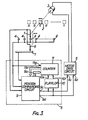
- the position controller further includes a second movable contact 6, and a contact or switching element 7 for detecting a position of the object 2 relative to the datum position c.
- the element 1 will hereinafter be called the first movable contact.
- These first and second movable contact 1 and 6 are linked in operation.
- the fixed contacts 4 are connected by a single common line as shown.
- the contact 7 is in contact with the second movable contact 6 at positions leftside from and including the datum position c, while the contact 7 is out of contact with the second movable contact 6 at positions rightside from the datum position c..
- the object 2 moves to the datum position c from any arbitrary position.
- the second movable contact 6 is in contact with the contact 7. So, such position can be detected as a position leftside from the datum position, c, and thus the controlling circuit 5 outputs a driving signal for driving the object 2, more specifically the controlling circuit 5 outputs a motor driving signal for driving the motor driving circuit 8 so as to rotate the motor 3 for the object 2 to be moved rightward.
- the object 2 is then moved back leftward until the first movable contact 1 comes into contact with the first fixed contact 4 after such return leftward movement.
- the position of such first fixed contact 4 is judged as the datum position by the controlling circuit 5, which at the same time outputs a driving or control signal to stop the rotation of the motor 3. In such manner, the object 2 can be brought to the datum position.
- the second movable contact 6 is not in contact with the contact 7. So, the position of the object is judged as being to the rightside from the datum position c by the controlling circuit 5, which at the same time outputs a driving or control signal to move the object 2 leftward.
- the position, where the first movable contact 1 first comes into contact with the first fixed contact 4 after the second movable contact 6 comes into contact with the contact 7, is judged as the datum position by the controlling circuit 5, which at the same time outputs a driving or control signal to stop the rotation of the motor 3.
- the object 2 can arrive at the datum position c in accordance with the same algorithm.
- a counting means in the controlling circuit 5 By presetting a counting means in the controlling circuit 5 at an initial value at the time the object 2 arrives at the datum position c, and by up-counting or down-counting the counting means in accordance with breaking or making, namely switching off or on, between the first movable contact 1 and the fixed contacts 4, the value of the counting means can be made to correspond to the moved position of the object 2. So, by moving the object 2 in accordance with such counter value, the necessary multiposition controlling can be achieved.
- FIG 3 shows a specific example of the controlling circuit 5 of Figure 2, in which the controlling circuit employs a position commanding means 9, a counting means 11, and a pulse signal holding means in the form of a flip-flop 10 for holding up-counting state or down-counting state of the counting means even when the supply of the driving signal is stopped.
- Such controlling circuit or means 5 is in practice preferred to be integrally constructed by a single microcomputer which has the functions of the position commanding means, the counting means and the pulse holding means without using discrete circuits respectively for the three means.
- the three means are shown in Figure 3 as discrete circuits.
- the position commanding means or circuit 9 achieves various judgements or detections as described above with reference to Figure 2. That is, the position commanding circuit 9 receives various input signals from the contact 7, the fixed contacts 4, the first movable contact 1 and the second movable contact 6, and outputs various driving or control signals to the motor driving circuit 8. The output signals of the position commanding circuit 9 are also supplied to the counting means or counter 11 for achieving the above described . presetting, and further the output signals of the counter 11 are supplied back to the position commanding circuit 9 for achieving the movement of the object 2 in accordance with the counter value.
- the operation of the above counter 11 will be described. Let us assume now that a value "5" is preset in the counter 11 at the datum position c, and that the position commanding circuit 9 supplies output 9c to the input 8c of the driving circuit 8 of the motor 3 for causing the object 2 to move leftward. In such state, the counter 11 is set at its down-counting state by an output 10e of the flip-flop circuit 10. This flip-flop functions as a pulse signal holding means for holding an up-counting state or a down-counting state of the counter 11 when supply of the driving signal is stopped. Further, the fixed contact 4 is connected to an input 11g of the counter 11.
- the counter 11 down-counts by "1".
- the counter 11 further down-counts by "1” at the moment the first movable contact 1 next comes into contact with a fixed contact 4 while moving in the same direction. So, the counter value of the counter 11 corresponding to the position b is "3".
- the position commanding circuit 9 may stop the motor rotation (namely supply a driving or control signal to stop the motor rotation) for some reason just before the object 2 arrives at the position c while the first movable contact 1 is not in contact with any fixed contact 4.
- the motor still continues its rotation for a short time by virtue of its inertia and then stops.
- the first movable contact 1 finally gets into contact with a fixed contact 4, as a special case.
- the flip-flop 10 which remains at its up-counting or down-counting state even in such special case, the counting operation can be maintained. This is one of the features of this embodiment of the invention, and thereby counting failure can be prevented, and an accurate counting corresponding to any position of the object 2 can be achieved.
Landscapes
- Physics & Mathematics (AREA)
- General Physics & Mathematics (AREA)
- Engineering & Computer Science (AREA)
- Automation & Control Theory (AREA)
- Control Of Position Or Direction (AREA)
Claims (4)
Applications Claiming Priority (2)
| Application Number | Priority Date | Filing Date | Title |
|---|---|---|---|
| JP56194063A JPS5896310A (ja) | 1981-12-02 | 1981-12-02 | 多位置制御装置 |
| JP194063/81 | 1981-12-02 |
Publications (3)
| Publication Number | Publication Date |
|---|---|
| EP0080904A2 EP0080904A2 (de) | 1983-06-08 |
| EP0080904A3 EP0080904A3 (en) | 1984-07-11 |
| EP0080904B1 true EP0080904B1 (de) | 1989-07-05 |
Family
ID=16318329
Family Applications (1)
| Application Number | Title | Priority Date | Filing Date |
|---|---|---|---|
| EP82306408A Expired EP0080904B1 (de) | 1981-12-02 | 1982-12-02 | Mehrstellungssteuergerät |
Country Status (4)
| Country | Link |
|---|---|
| US (1) | US4565954A (de) |
| EP (1) | EP0080904B1 (de) |
| JP (1) | JPS5896310A (de) |
| DE (1) | DE3279801D1 (de) |
Families Citing this family (4)
| Publication number | Priority date | Publication date | Assignee | Title |
|---|---|---|---|---|
| JPS593512A (ja) * | 1982-06-30 | 1984-01-10 | Sony Corp | 位置制御システム |
| NZ214354A (en) * | 1984-11-30 | 1989-04-26 | Kierkegaard Soren | Sliding door controller:arrested door motion causes cessation or reversal of door movement according to door position |
| JPS62156489A (ja) * | 1985-12-28 | 1987-07-11 | ワイケイケイ株式会社 | 自動扉の異常時開閉制御方法 |
| US4888531A (en) * | 1987-02-12 | 1989-12-19 | Hormann Kg Antriebs- Und Steuerungstechnik | Variable drive mechanism for the panel of a gate or similar structure |
Family Cites Families (10)
| Publication number | Priority date | Publication date | Assignee | Title |
|---|---|---|---|---|
| US2800618A (en) * | 1955-04-06 | 1957-07-23 | Collins Radio Co | Seeking switch system |
| DE1125520B (de) * | 1961-09-05 | 1962-03-15 | Telefunken Patent | Motorgetriebene, drehrichtungsgesteuerte Einstellvorrichtung zur Einstellung einer Drehachse auf eine von mehreren Raststellungen |
| DE1918748A1 (de) * | 1969-04-14 | 1970-10-15 | Julien Pons | Elektrischer Impulsschreiber mit Digitalsteuerung |
| US3614574A (en) * | 1970-02-16 | 1971-10-19 | Hato R Hodges | Reversible follow up positioning device for mobile antenna structures or the like |
| US3850105A (en) * | 1972-12-29 | 1974-11-26 | Ibm | Apparatus for transferring articles through various processing sectors of a manufacturing system |
| JPS5832409B2 (ja) * | 1976-07-23 | 1983-07-13 | 株式会社日立製作所 | 駆動信号発生回路 |
| US4263539A (en) * | 1977-10-04 | 1981-04-21 | Zenith Radio Corporation | Automatic antenna positioning apparatus |
| JPS5593849A (en) * | 1978-12-30 | 1980-07-16 | Toyoda Automatic Loom Works | Timing setting method and apparatus in loom |
| CH651948A5 (de) * | 1980-08-17 | 1985-10-15 | Maag Zahnraeder & Maschinen Ag | Positionsregelvorrichtung mit einer digitalen inkrementellen messeinrichtung. |
| US4429267A (en) * | 1981-06-22 | 1984-01-31 | Manhattan Engineering Company, Inc. | Digital positioning systems having high accuracy |
-
1981
- 1981-12-02 JP JP56194063A patent/JPS5896310A/ja active Pending
-
1982
- 1982-12-01 US US06/445,988 patent/US4565954A/en not_active Expired - Fee Related
- 1982-12-02 EP EP82306408A patent/EP0080904B1/de not_active Expired
- 1982-12-02 DE DE8282306408T patent/DE3279801D1/de not_active Expired
Also Published As
| Publication number | Publication date |
|---|---|
| US4565954A (en) | 1986-01-21 |
| JPS5896310A (ja) | 1983-06-08 |
| DE3279801D1 (en) | 1989-08-10 |
| EP0080904A3 (en) | 1984-07-11 |
| EP0080904A2 (de) | 1983-06-08 |
Similar Documents
| Publication | Publication Date | Title |
|---|---|---|
| SU831060A3 (ru) | Система управлени шпинделем | |
| US4356439A (en) | Stepper motor control | |
| US5252897A (en) | Dual motor wiper control | |
| GB2149945A (en) | Circuit arrangement comprising a microcomputer | |
| US4481585A (en) | System for selectively controlling motor vehicle electrical loads | |
| US4565954A (en) | Multiposition controller | |
| US3322994A (en) | Electrical apparatus including analog and digital control for an element | |
| US4430578A (en) | Device for the input of adjustment values in electronic switching systems | |
| US4513234A (en) | Method and apparatus for controlling zero-point return of a movable element | |
| US5670857A (en) | Method of returning to an absolute zero point for use by an industrial controller | |
| JPH0431808A (ja) | ズームレンズの制御装置 | |
| EP0068802B1 (de) | Verfahren und Einrichtung für die Dämpfung eines Schrittmotors durch Benützung der nicht-aktiven Windungen | |
| US4430605A (en) | Motor control system utilizing switched controller | |
| KR850000489B1 (ko) | 구동 전동기 전류제어 기능을 가진 산업용 로보트장치 | |
| US6194857B1 (en) | Electromotive actuator | |
| US4509445A (en) | Sewing machine control device | |
| US4955306A (en) | Sewing machine | |
| JPH0612845B2 (ja) | モータアンテナ駆動装置 | |
| JPH01107620A (ja) | 負荷時タップ切換装置 | |
| US4027222A (en) | Manual control in a motion control system | |
| JPH0448307A (ja) | 位置制御装置 | |
| JPH033131B2 (de) | ||
| KR100264586B1 (ko) | 무인 자동차 변속 제어 장치 | |
| US5823868A (en) | Air-conditioning system malfunction compensation method and apparatus | |
| EP0383936A1 (de) | Fernsteuerung von motoren |
Legal Events
| Date | Code | Title | Description |
|---|---|---|---|
| PUAI | Public reference made under article 153(3) epc to a published international application that has entered the european phase |
Free format text: ORIGINAL CODE: 0009012 |
|
| AK | Designated contracting states |
Designated state(s): DE FR GB |
|
| PUAL | Search report despatched |
Free format text: ORIGINAL CODE: 0009013 |
|
| AK | Designated contracting states |
Designated state(s): DE FR GB |
|
| 17P | Request for examination filed |
Effective date: 19841219 |
|
| 17Q | First examination report despatched |
Effective date: 19860915 |
|
| R17C | First examination report despatched (corrected) |
Effective date: 19870508 |
|
| GRAA | (expected) grant |
Free format text: ORIGINAL CODE: 0009210 |
|
| AK | Designated contracting states |
Kind code of ref document: B1 Designated state(s): DE FR GB |
|
| REF | Corresponds to: |
Ref document number: 3279801 Country of ref document: DE Date of ref document: 19890810 |
|
| ET | Fr: translation filed | ||
| PLBE | No opposition filed within time limit |
Free format text: ORIGINAL CODE: 0009261 |
|
| STAA | Information on the status of an ep patent application or granted ep patent |
Free format text: STATUS: NO OPPOSITION FILED WITHIN TIME LIMIT |
|
| 26N | No opposition filed | ||
| PGFP | Annual fee paid to national office [announced via postgrant information from national office to epo] |
Ref country code: GB Payment date: 19941122 Year of fee payment: 13 |
|
| PGFP | Annual fee paid to national office [announced via postgrant information from national office to epo] |
Ref country code: DE Payment date: 19941208 Year of fee payment: 13 |
|
| PGFP | Annual fee paid to national office [announced via postgrant information from national office to epo] |
Ref country code: FR Payment date: 19941209 Year of fee payment: 13 |
|
| PG25 | Lapsed in a contracting state [announced via postgrant information from national office to epo] |
Ref country code: GB Effective date: 19951202 |
|
| GBPC | Gb: european patent ceased through non-payment of renewal fee |
Effective date: 19951202 |
|
| PG25 | Lapsed in a contracting state [announced via postgrant information from national office to epo] |
Ref country code: FR Effective date: 19960830 |
|
| PG25 | Lapsed in a contracting state [announced via postgrant information from national office to epo] |
Ref country code: DE Effective date: 19960903 |
|
| REG | Reference to a national code |
Ref country code: FR Ref legal event code: ST |