EP0083989A2 - Bildaufbereitungsgerät - Google Patents
Bildaufbereitungsgerät Download PDFInfo
- Publication number
- EP0083989A2 EP0083989A2 EP83300117A EP83300117A EP0083989A2 EP 0083989 A2 EP0083989 A2 EP 0083989A2 EP 83300117 A EP83300117 A EP 83300117A EP 83300117 A EP83300117 A EP 83300117A EP 0083989 A2 EP0083989 A2 EP 0083989A2
- Authority
- EP
- European Patent Office
- Prior art keywords
- sticking
- regions
- cut
- cut regions
- region
- Prior art date
- Legal status (The legal status is an assumption and is not a legal conclusion. Google has not performed a legal analysis and makes no representation as to the accuracy of the status listed.)
- Granted
Links
Images



Classifications
-
- H—ELECTRICITY
- H04—ELECTRIC COMMUNICATION TECHNIQUE
- H04N—PICTORIAL COMMUNICATION, e.g. TELEVISION
- H04N1/00—Scanning, transmission or reproduction of documents or the like, e.g. facsimile transmission; Details thereof
- H04N1/387—Composing, repositioning or otherwise geometrically modifying originals
- H04N1/3872—Repositioning or masking
- H04N1/3873—Repositioning or masking defined only by a limited number of coordinate points or parameters, e.g. corners, centre; for trimming
- H04N1/3875—Repositioning or masking defined only by a limited number of coordinate points or parameters, e.g. corners, centre; for trimming combined with enlarging or reducing
-
- G—PHYSICS
- G06—COMPUTING OR CALCULATING; COUNTING
- G06T—IMAGE DATA PROCESSING OR GENERATION, IN GENERAL
- G06T11/00—Two-dimensional [2D] image generation
- G06T11/60—Creating or editing images; Combining images with text
-
- H—ELECTRICITY
- H04—ELECTRIC COMMUNICATION TECHNIQUE
- H04N—PICTORIAL COMMUNICATION, e.g. TELEVISION
- H04N1/00—Scanning, transmission or reproduction of documents or the like, e.g. facsimile transmission; Details thereof
- H04N1/387—Composing, repositioning or otherwise geometrically modifying originals
Definitions
- This invention relates to a document editing apparatus for editing documents or manuscripts containing characters and images without any hand work.
- a simplest editing method is to manually stick cut regions of documents on a sheet. This method is very uneconomical from the standpoint of the preservation of the documents as well as the effective utilization of labor. As a solution to this problem, the following methods may be considered.
- a first method is to enter specific marks and symbols designating an editing operation on a specific sheet and read out them by a facsimile unit so that the editing operation is carried out.
- this method it is necessary for an editor to designate cut regions of documents and corresponding sticking regions of the sheet.
- the editing designation marks entered on the document With the editing designation marks entered on the document, the document is soiled, presenting a document management problem.
- the use of the specific sheet prevents the wide acceptance of the image editing apparatus.
- a second method is to perform an editing operation utilizing a computer.
- an editing mode and editing regions are designated through a keyboard, while displaying the document on a display unit.
- This method is desirable from the standpoint of the management of documents, because the documents can be stored as image data. It is necessary, however, for the editor to designate the cut regions of the documents and corresponding sticking regions of the sheet to the apparatus through the keyboard. It is difficult and time-consuming to prepare a new document by, for example, cutting desired regions from a plurality of documents and sticking them on a sheet of paper. For this reason, the editing operation depends much on the skill of the editor.
- An object of this invention is to provide an image editing apparatus which can prepare a new document by extracting out of existing documents the image data of any proper regions and synthesizing them, whereby a ready editing operation is performed.
- a plurality of basic sticking patterns are initially prepared, according to which a plurality of cut regions from a plutality of documents are stuck on a sheet.
- a sticking region computer calculates the coordinates of those sticking regions corresponding to the cut regions in connection with the respective sticking patterns.
- An image processor causes image information of the respective cut regions which are stored in a first RAM to be transferred to the memory location of a second RAM which is cesignated by the calculated coordinate data of the sticking regions.
- An image editing process is performed with respect to the respective basic sticking patterns and displayed on a CRT display.
- An editing apparatus of Fig. 1 comprises an input section 11, output section 12, control section 13, image processor 14, instruction input section 15, sticking region computer 16 and reduction circuit 17.
- An editing operation is automatically performed by control section 13 and image processor 14 which are comprised of a microcomputer such as Intel 8085.
- Control section 13 controls the whole operation of the apparatus, and image processor 14 effects the editing control such as the calculation of sticking regions on a sheet and transfer of the image information.
- Reference numeral 20 designates a control signal bus connecting control section 13 to the associated parts and reference numeral 21 designates a bus for image processing signals which connects image processor 14 to the parts associated with the editing operation.
- Reference numeral 22 denotes an image signal bus for connecting image processor 14 to those parts which handle the image information.
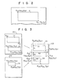
- the editing properly performed by the image editing apparatus of this invention is to stick , for example, cut regions C 1 and C 2 of a first document 101 and cut region C 3 of a second document 102 on one sheet 103 as shown in Fig. 3.
- a plurality of basic sticking patterns are prepared to permit a plurality of cut regions to be stuck on one sheet.
- a plurality of basic patterns are found which permits the sticking of a plurality of cut regions, it is possible to select one of them.
- documents 101, 102 to be cut are of the same size (for example, an A4 size) as that of sheet 103 on which the cut regions are stuck.
- Input section 11 includes a scanner 111 and a document file 112 using an optical disc or a magnetic disc.
- a document to be edited is an input document 18 to be read out by scanner 111 or a document stored in file 112 which is retrieved by instruction input section 15.
- Such document is displayed on a first CRT (cathode ray tube) display 121 of output section 12. While observing the document on display 121, two points P C0 and P C1 on a diagonal line of a rectangular region to be cut which is shown in Fig. 2 are designated by a light pen of instruction input section 15.
- the coordinate (X CO , Y CO ) and (X C1 , Y C1 ) on the two points are detected in instruction input section 15 and these coordinate data are stored in a RAM (random access memory) in sticking region computer 16.
- the other regions to be cut of the same document and/or the regions to be cut of another document are designated in a similar manner.
- image processor 14 extracts the image information of the cut regions on the basis of the coordinate data of the cut regions to permit them to be stored in first buffer 124 (512 K byte RAM).
- the coordinate data (X DO , Y DO through X D5 , Y D5 ) of the sticking regions as indicated by D 1 , D 2 , D 3 on a sheet 103 of Fig. 3 are calculated on the basis of the coordinate data of the cut regions which are stored in sticking region computer 16.
- sticking region computer 16 comprises a RAM for storing the coordinate data of the cut regions and ROM (read only memory) for storing the process steps.
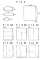
- ROM further stores information on six basic sticking pattern as shown in Figs. 5A to 5F, as to how cut regions C 1 , C 2 , C 3 are stuck on sheet 103 and data-(X max , Y max of sheet 103 as shown in Fig. 4) as to the size of sheet 103.
- Image processor 14 judges whether or not all the cut regions C 1 , C 2 , C 3 can be stuck on sheet 103 in connection with all the basic sticking patterns on the basis of the coordinate data of the cut regions which are stored in sticking region computer 16, judges whether or not the reduction of the cut regions is necessary for sticking, and finds the coordinates X DO , Y D0 through X D5 , Y D5 of regions D l , D 2 , D 3 which can be stuck on sheet 103 as shown in Fig. 3.
- the coordinate data of sticking regions D 1 , D 2 , D 3 are computed with respect to those basic patterns which are judged as fit patterns. These coordinate data, together with the coordinate data of the cut regions, are stored in RAM.
- cut regions C l , C 2 , C 3 are stuck on sheet 103 according to the basic pattern as shown in Fig. 5A.
- image processor 14 designates the addresses of sticking regions Dl, D2, D3 of a second buffer (512 K byte RAM) 125 on the basis of the computed coordinate data and transfer the image information of the cut regions stored in first buffer 124 to the memory locations of second buffer 125 which are designated by these addresses.
- the image information of sticking regions D 1 , D 2 , D 3 are stored in the A4 size memory locations of second buffer 125 in such a relation as indicated on the right side of Fig. 3 which shows an edited document.
- the "edited” information are stored in second buffer 125 for each basic pattern which permits the sticking of cut regions C l , C 2 , C 3 .
- the "edited" image information associated with A4 size which are stored in second buffer 125 are displayed on second CRT display 122 for each fit basic pattern.
- the editor can select a desirable pattern.
- the image information edited according to the selected pattern may be stored in image file 112 and/or may be printed out by a printer 123 as a hard copy 19.
- the operation of the editing apparatus of Fi g . 1 will be described below in more detail by referring to a flow chart.
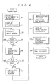
- Fig. 6 shows a whole flow chart associated with the operation of the image editing apparatus.
- the editor retrieves a to-be-edited document stored in image file 112 through a keyboard of instruction input section 15 at step S l .
- the document to be edited may otpically be read out by scanner 111.
- the retrieved document is displayed on first CRT display 121.
- the editer goes ahead with the editing operation, while watching first CRT display 121.
- the editor designates a cut region C, as shown in Fig. 2, by pointing at two points P C0 , P C1 on the cut region C with the light pen of instruction input section 15.
- the editor indicates the completion of the designation, through the keyboard.
- judgement is made as to whether or not the designation of the cut region is completed. If the designation of cut region is completed, then the process goes to step 8 5 .
- image processor 14 stores the coordinate data (X CO , YCO , XC1 , YC1 ) on the two points P CO , P C1 of the cut region C which are detected at instruction input section 15 in the RAM of sticking region computer 16 and the image information of the cut region of document in first buffer 124 on the basis of the detected coordinate data.
- the editor may input, through the keyboard, information as to the attributes of the cut region, such as the priority, inhibition of the reduction and the order of cutting.
- the information as to the attributes, together with the coordinate data, are stored in RAM of sticking region computer 16.
- the cut regions C 1 , C 2 of first document 101 and cut region C 3 of second document 102 are designated, the coordinate data (X CO , Y CO ) through (X C5 , Y C5 ) on points P CO through P C5 of the cut regions are stored in RAM and the image information of the cut regions are stored in first buffer 124 according to the order of the designation.
- step S 7 the sticking regions corresponding to cut regions C 1 , C 2 , C 3 are calculated.
- step Sg the image editing (the transfer of the image information) is carried out at step Sg. Namely, at this step, image processor 14 transfers the image information from first buffer 124 to second buffer 125 on the basis of the coordinate data of the sticking regions. The image editing is carried out for each fit basic pattern.
- step S 9 the image processor 14 reads the "edited" image information out of second buffer 125 for each fit basic pattern according to an instruction of the editor and displays them on CRT display 122.
- step S 10 the editor can select a desired edited document through the keyboard, while viewing the screen of second CRT display 122.
- a step S 11 the selected document is printed out by printer 123 or stored in image file 112.
- step S 701 judgement is made as to whether or not the cut regions can be stuck on the sheet, according to the basic patterns as shown in Fig. 5A to 5F, on the basis of the coordinate data of cut regions C 1 , C 2 , C 3 which are stored in the RAM in sticking region computer 16.
- the lateral length (the width) X and longitudinal length (the height) Y of the cut regions can readily been obtained and examination is made as to whether or not the cut regions can be stuck on the sheet 103 of a dimension X max x Y max according to the basic patterns.
- Fig. 5A shows a basic pattern for sticking three cut regions in the vertical direction
- Fig. 5B shows a basic pattern for sticking three cut regions such that one cut region is arranged at the upper section of the pattern with the remaining two cut regions located side by side in the horizontal direction
- Fig. 5C shows a basic pattern for sticking three cut regions such that two cut regions are arranged side by side at the upper section of the pattern with the remaining one region located at the lower section thereof.
- Fig. 5D shows a basic pattern for sticking three cut regions side by side in the horizontal direction.
- Fig. 5E shows a basic pattern for sticking three cut regions such that one cut region is arranged on the left side with the remaining two cut regions located one above the other on the right side of the pattern.
- Fig. 5A shows a basic pattern for sticking three cut regions in the vertical direction
- Fig. 5B shows a basic pattern for sticking three cut regions such that one cut region is arranged at the upper section of the pattern with the remaining two cut regions located side by side in the horizontal direction
- 5F shows a basic pattern for sticking three cut regions such that two cut regions are arranged one above the other at the left side of the pattern with the remaining one cut region located at the right side thereof.
- the document to be edited is of the same size as that of the document on which the cut regions are stuck. Therefore, the width (X 1 , X 2 , X 3 ) of the cut region is below X max and the hight (Y 1 , Y 2 , Y 3 ) thereof is below Y max .
- image processor 14 finds a sum (Y 1 + Y2 + Y3 ) of heights of cutting regions C l , C 2 , C 3 . If Y 1 + Y 2 + Y 3 ⁇ Ymax, the cut regions C 1 , C 2 , C 3 are judged as being capable of being stuck on the sheet according to the sticking pattern of Fig. 5A. If X 1 + X 2 + X 3 ⁇ Xmax, the cut regions C l , C 2 , C 3 are judged as being capable of being stuck on the sheet according to the sticking pattern of Fig. 5D.
- the tree cut regions can be stuck on the sheet according to the pattern of Fig. 5B with the cut region C 2 located at the upper section of the pattern.
- the three cut regions C 1 , C 2 , C 3 are stuck on the sheet according to the pattern of Fig. 5B with the cut region C 3 located on the upper section of the pattern. In this way, the judgement is continued until one of the three sticking ways is found usable. With respect to each of the basic patterns as shown in Fig. 5C, 5E and 5F, there are three sticking ways and such judgement is made according to the respective requirements.
- step S 702 When, at step S 702 , the cut regions are judged as being not capable of being stuck on the sheet according to the respective basic pattern as they stand, a reduction flag is attached at step S 703 to the data of the respective cut regions, indicating that it is impossible to stick the cut regions on the sheet according to the judged basic pattern.
- step S 704 examination is made as to whether or not the judgement is made in connection with all the basic patterns. If the answer is in the negative, the process goes back to step S 701 . Then, the cut regions are judged in connection with the next basic pattern.
- step S 705 judgement is made, at step S 705 , as to whether or not there is any basic pattern with no reduction flag attached thereto, i.e., any basic pattern which permits the sticking of the regions C l , C 2 , C 3 . If the answer is in the affirmative, the basic pattern with the reduction flag attached thereto is discarded at step 5 706 . That, at step S 745 , the answer is in the negative means that there is no basic pattern with no reduction flag attached thereto, i.e., it is impossible to stick the cut regions on the sheet according to each of all the basic patterns without being reduced.
- step S 707 judgement is made as to whether or not it is necessary to reduce the cut region in connection with the individual basic pattern on the basis of the reduction flag. If reduction is necessary, the reduction process is carried out at step S 709 .
- step S 701 the coordinate data of a new cut region which has been subjected to the reduction process are stored in the RAM of sticking region computer 16. If reduction is not necessary, the first coordinate data of the cut region are stored.
- step S 711 judgement is made as to whether or not it is necessary to reduce the cut region in connection with all the basic patterns. If the answer is in the negative, those steps beginning with step S 707 are repeated in connection with the remaining basic patterns. If the answer is in the affirmative, at step S 712 , calculation is made of the coordinates of the sticking regions D 1 , D 2 , D 3 in the fit basic pattern according to an order of the areas of cut regions C l , C 2 , C 3 as will be set out later in more detail. At step S 713 , judgement is effected as to whether or not the calculation of the sticking regions in connection with all the basic patterns is completed. If the answer is in the affirmative, then an image editing process is performed.
- Step S 712 at which the sticking regions are calculated will be explained below by referring to Fig. 8.
- the coordinates of sticking region D 1 are calculated.
- the coordinates (X D0 , Y DO ) on a point P DO of region D 1 are stored, as the head address of the basic pattern of Fig. 5A, in the ROM of sticking region computer 16.
- the coordinates of sticking region D 3 are found.
- the coordinates of the sticking regions D l , D 2 , D 3 are found in connection with each of the fit basic patterns.
- the coordinate data of those sticking regions are stored in the RAM of sticking region computer 16 for each basic pattern.
- image processor 14 reads image information in cut region Clout of first buffer 124 to temporarily store them therein.
- image processor 14 designates that address of a memory area of second buffer 125, on the basis of the calculated coordinate data of the sticking region D 1 , where the image information in cut region C 1 are to be stored.
- image processor 14 writes the image information in cut region C 1 into the address which is designated by second buffer 125.
- step S 733 judgement is effected as to whether or not the transfer of the image information of all the cut regions is completed. If the answer is in the negative, the above-mentioned steps are repeated. As a result of these processes, the image information of sticking regions D 1 , D 2 , D 3 are stored in an A4 size memory area of second buffer 125 in that relation as shown in Fig. 3. The edited image information is stored in second buffer 125 for each of fit basic patterns.
- step S 740 the attributes of the cut regions are judged and if the reduction is not inhibited for the cut regions, the process goes to step S 741 .
- step S 740 if reducible cut regions C 1 , C 2 , C 3 are edited such that they-are arranged vertically according to the basic pattern as shown, for example, in Fig. 5A, the heights Y 1 ', Y 2 ', Y 3 ' of the cut regions C l , C 2 , C 3 are arbitrarily found to provide Y 1 ' + Y 2 ' + Y 3 ' ⁇ Y max .
- step S 742 judgement is performed as to whether or not Y 1 ', Y 2 ', Y 3 ' are greater than Y m i n .
- Y m i n With the height of a pre-edited display character and readable minimum value of the reduced character representing A and B, respectively, Y m i n is given by
- step S 741 judgement is made as to whether or not Y 1 ' ⁇ Y lmi n , Y 2'i Y 2 m i n and Y 3 ' ⁇ Y 3m i n . If the answer is in the negative, i.e., the reduced character is illegible, the basic pattern as shown in Fig. 5A is abandoned.
- step S 742 If at step S 742 the answer is in the affirmative, the process goes to step S 743 in which reduction rates Y 1 '/Y 1 , Y 2 '/Y 2 and Y 3 '/Y 3 are calculated the reduction rates are stored in the RAM of sticking region computer 16.
- the coordinates of points P D1 through P D5 of sticking regions D 1 , D 2 , D 3 as shown in Fig. 3 are calculated on the basis of the reduction rates. Where the sticking pattern as shown in Fig. 3 is involved, calculation is made of the coordinates of the sticking regions which are reduced in the Y-axis direction only. These coordinate data are stored in the RAM of sticking region computer 16.
- the image information to be stored in that address of second buffer 125 which is designated by image processor 14 and based on the reduced coordinates is supplied from image processor 14 through reduction circuit 17 to second buffer 125.
- Reduction circuit 17 reduces the image information in accordance with the reduction rate for each region. The reduction process is performed for each basic pattern as shown in each of Figs. 5A through 5F. Those basic patterns which make the image not readable upon reduction are discarded.
- step S 3 it is desirable to calculate the sticking regions according to the designation order of the cut regions, i.e., the order of cutting.
- those data hereinafter referred to the designation data
- designation data relating to the order of cutting are obtained at step S 3 .
- the coordinate data and designation data are stored in the RAM of sticking region computer 16.
- the following steps correspond to the steps in Fig. 7.
- judgement is made as to whether or not cut regions C 1 , C 2 , C 3 can be stuck on the sheet, according to the basic patterns of Figs. 5A through 5H, on the basis of the coordinate data of the cut regions.
- the basic sticking pattern data is stored in the ROM of sticking region computer 16 for each number (2, 3, 4 ...) of used cut regions.
- the cut region has been explained as being a rectangular region, because the designation of the rectangular region is easiest. Circular, square and polygonal regions may be designated at the user's request. Not only the rectangular coordinates, but also the polar coordinates, may be used for coordinate designation.
- the rectangular region may be designated by two points on the diagonal, as well as one point and length of two sides.
- reduction circuit 17 is used, a circuit for selectively performing reduction and enlargement of image information may be used.
- An image editing apparatus of this invention may be coupled to a facsimile unit so as to edit received documents and transmit the edited documents.
Landscapes
- Engineering & Computer Science (AREA)
- Multimedia (AREA)
- Signal Processing (AREA)
- Physics & Mathematics (AREA)
- General Physics & Mathematics (AREA)
- Theoretical Computer Science (AREA)
- Document Processing Apparatus (AREA)
- Processing Or Creating Images (AREA)
- Editing Of Facsimile Originals (AREA)
Applications Claiming Priority (2)
| Application Number | Priority Date | Filing Date | Title |
|---|---|---|---|
| JP887/82 | 1982-01-08 | ||
| JP57000887A JPS58119076A (ja) | 1982-01-08 | 1982-01-08 | 画像編集装置 |
Publications (3)
| Publication Number | Publication Date |
|---|---|
| EP0083989A2 true EP0083989A2 (de) | 1983-07-20 |
| EP0083989A3 EP0083989A3 (en) | 1984-12-12 |
| EP0083989B1 EP0083989B1 (de) | 1987-12-16 |
Family
ID=11486180
Family Applications (1)
| Application Number | Title | Priority Date | Filing Date |
|---|---|---|---|
| EP83300117A Expired EP0083989B1 (de) | 1982-01-08 | 1983-01-10 | Bildaufbereitungsgerät |
Country Status (4)
| Country | Link |
|---|---|
| US (1) | US4538183A (de) |
| EP (1) | EP0083989B1 (de) |
| JP (1) | JPS58119076A (de) |
| DE (1) | DE3374966D1 (de) |
Cited By (13)
| Publication number | Priority date | Publication date | Assignee | Title |
|---|---|---|---|---|
| GB2152323A (en) * | 1983-11-25 | 1985-07-31 | Canon Kk | An image processing apparatus |
| DE3523042A1 (de) * | 1984-06-28 | 1986-01-02 | Canon K.K., Tokio/Tokyo | Bildverarbeitungssystem |
| GB2168872A (en) * | 1984-12-25 | 1986-06-25 | Dainippon Screen Mfg | Editing reproduced picture images |
| EP0185904A1 (de) * | 1984-12-26 | 1986-07-02 | International Business Machines Corporation | Nach Mass angefertigter Dokumentenaufbau |
| EP0167342A3 (en) * | 1984-06-30 | 1989-02-15 | Kabushiki Kaisha Toshiba | Document image editing device |
| EP0179373A3 (en) * | 1984-10-11 | 1989-03-22 | Dai Nippon Insatsu Kabushiki Kaisha | Method of processing picture data for printing process and device implementing the same |
| EP0269130A3 (en) * | 1986-11-28 | 1989-11-23 | Mita Industrial Co. Ltd. | Editing area setting method and editing area setting apparatus in an image forming apparatus |
| FR2631766A1 (fr) * | 1988-05-17 | 1989-11-24 | Sony Corp | Procede et appareil de traitement d'un signal d'image fixe |
| GB2233185A (en) * | 1989-04-27 | 1991-01-02 | Sony Corp | Still image filing apparatus |
| EP0272102A3 (de) * | 1986-12-17 | 1991-03-13 | Oki Electric Industry Company, Limited | Elektronische Drucktafeln |
| EP0316005A3 (de) * | 1987-11-12 | 1991-03-27 | Kabushiki Kaisha Toshiba | Figurkodierer |
| EP0531030A1 (de) * | 1991-08-22 | 1993-03-10 | Riso Kagaku Corporation | Verfahren und Gerät zur Bearbeitung eines Bildes |
| GB2313728A (en) * | 1996-05-30 | 1997-12-03 | Eastman Kodak Co | Multiple page printing |
Families Citing this family (62)
| Publication number | Priority date | Publication date | Assignee | Title |
|---|---|---|---|---|
| US4691238A (en) * | 1982-10-21 | 1987-09-01 | Dainippon Screen Mfg. Co., Ltd. | Method and apparatus of storing image data into a memory in a layout scanner system |
| US5142594A (en) * | 1983-04-02 | 1992-08-25 | Canon Kabushiki Kaisha | Image data communication control system |
| JPH0757003B2 (ja) * | 1983-05-09 | 1995-06-14 | 大日本スクリ−ン製造株式会社 | 画像走査記録装置 |
| US4695895A (en) * | 1983-11-02 | 1987-09-22 | Canon Kabushiki Kaisha | Image processing system |
| JPS60140472A (ja) * | 1983-12-28 | 1985-07-25 | Hitachi Ltd | 対話型フオント・パタ−ン作成・修正・合成制御装置 |
| US4726065A (en) * | 1984-01-26 | 1988-02-16 | Horst Froessl | Image manipulation by speech signals |
| US5068741A (en) * | 1984-02-29 | 1991-11-26 | Canon Kabushiki Kaisha | Image output apparatus for reproducing, adjacent each other, leading image data portions of plural image units |
| JPS60195589A (ja) * | 1984-03-19 | 1985-10-04 | オリンパス光学工業株式会社 | 画像表示装置 |
| JPS60262122A (ja) * | 1984-06-08 | 1985-12-25 | Dainippon Screen Mfg Co Ltd | 原画貼付方法 |
| US4710821A (en) * | 1984-06-14 | 1987-12-01 | Canon Kabushiki Kaisha | Image recording apparatus |
| US4739477A (en) * | 1984-08-30 | 1988-04-19 | International Business Machines Corp. | Implicit creation of a superblock data structure |
| USRE36653E (en) * | 1984-09-06 | 2000-04-11 | Heckel; Paul C. | Search/retrieval system |
| US4631599A (en) * | 1984-10-05 | 1986-12-23 | Institute For Scientific Information, Inc. | Selective optoelectronic copier |
| JPS6195665A (ja) * | 1984-10-17 | 1986-05-14 | Fuji Xerox Co Ltd | 画像読取り装置 |
| EP0381299B1 (de) * | 1984-11-14 | 1998-08-12 | Canon Kabushiki Kaisha | Bildverarbeitungssystem |
| US5065257A (en) * | 1985-03-20 | 1991-11-12 | Canon Kabushiki Kaisha | Image processing apparatus with means for compensating for dust., etc., on an original |
| JP2526031B2 (ja) * | 1985-05-08 | 1996-08-21 | 株式会社リコー | 画像通信装置 |
| EP0225191B1 (de) * | 1985-11-28 | 1991-12-11 | Canon Kabushiki Kaisha | Dokumentverarbeitungssystem |
| US4656525A (en) * | 1985-12-04 | 1987-04-07 | Polaroid Corporation | Electronic imaging copier |
| US4760463A (en) * | 1985-12-07 | 1988-07-26 | Kabushiki Kaisha Toshiba | Image scanner apparatus with scanning function |
| US4775942A (en) * | 1985-12-09 | 1988-10-04 | International Business Machines Corporation | Seed and stitch approach to embedded arrays |
| EP0235456B1 (de) * | 1985-12-13 | 1999-03-24 | Canon Kabushiki Kaisha | Bildverarbeitungsgerät und -verfahren mit Blöcken von komprimierten Daten |
| US4656524A (en) * | 1985-12-23 | 1987-04-07 | Polaroid Corporation | Electronic imaging copier |
| JP2823160B2 (ja) * | 1987-03-03 | 1998-11-11 | キヤノン株式会社 | 画像処理装置 |
| US5012353A (en) * | 1987-06-04 | 1991-04-30 | Hitachi, Ltd. | Apparatus for reading original |
| JP2695802B2 (ja) * | 1987-11-16 | 1998-01-14 | 株式会社日立製作所 | 電子ファイル装置 |
| US4881130A (en) * | 1987-12-07 | 1989-11-14 | Ricoh Company, Ltd. | Image editing system for an image recording apparatus with the capability of marking an edited image area in the form of a vector |
| US4888812A (en) * | 1987-12-18 | 1989-12-19 | International Business Machines Corporation | Document image processing system |
| US5179650A (en) * | 1988-01-21 | 1993-01-12 | Kabushiki Kaisha Toshiba | Method and apparatus for editing documents |
| US5437005A (en) * | 1988-04-01 | 1995-07-25 | International Business Machines Corporation | Graphical method of processing multiple data blocks |
| JPH0212383A (ja) * | 1988-06-29 | 1990-01-17 | Fujikura Ltd | 画像合成装置 |
| JPH0640219B2 (ja) * | 1988-10-07 | 1994-05-25 | 大日本スクリーン製造株式会社 | 切り抜きマスクデータの作成方法 |
| JP3020957B2 (ja) * | 1988-11-18 | 2000-03-15 | キヤノン株式会社 | 画像処理方法 |
| JPH02194771A (ja) * | 1989-01-24 | 1990-08-01 | Fujitsu Ltd | 画像送信装置及び画像受信装置 |
| US5140440A (en) * | 1989-03-28 | 1992-08-18 | Ricoh Company, Ltd. | Method of detecting a processing area of a document for an image forming apparatus |
| US5115320A (en) * | 1989-09-20 | 1992-05-19 | Olympus Optical Co., Ltd. | Apparatus for editing and printing a video image |
| JPH07115534A (ja) * | 1993-10-15 | 1995-05-02 | Minolta Co Ltd | 画像読取装置 |
| US5191440A (en) * | 1990-03-29 | 1993-03-02 | Levine Alfred B | Multiple photocopier system with memory and composite processing |
| JPH0771187B2 (ja) * | 1990-05-15 | 1995-07-31 | 富士ゼロックス株式会社 | 画像記録装置 |
| JP2613958B2 (ja) * | 1990-05-24 | 1997-05-28 | シャープ株式会社 | 文書編集装置 |
| US5289570A (en) * | 1990-10-10 | 1994-02-22 | Fuji Xerox Co., Ltd. | Picture image editing system for forming boundaries in picture image data in a page memory device |
| US5504674A (en) * | 1991-02-19 | 1996-04-02 | Ccc Information Services, Inc. | Insurance claims estimate, text, and graphics network and method |
| US5432904A (en) * | 1991-02-19 | 1995-07-11 | Ccc Information Services Inc. | Auto repair estimate, text and graphic system |
| US5465163A (en) * | 1991-03-18 | 1995-11-07 | Canon Kabushiki Kaisha | Image processing method and apparatus for processing oversized original images and for synthesizing multiple images |
| US5231698A (en) * | 1991-03-20 | 1993-07-27 | Forcier Mitchell D | Script/binary-encoded-character processing method and system |
| US6434581B1 (en) * | 1991-03-20 | 2002-08-13 | Microsoft Corporation | Script character processing method for interactively adjusting space between writing element |
| US5953735A (en) * | 1991-03-20 | 1999-09-14 | Forcier; Mitchell D. | Script character processing method and system with bit-mapped document editing |
| US5220649A (en) * | 1991-03-20 | 1993-06-15 | Forcier Mitchell D | Script/binary-encoded-character processing method and system with moving space insertion mode |
| JP2959647B2 (ja) * | 1991-07-31 | 1999-10-06 | キヤノン株式会社 | 文書画像処理装置 |
| JPH05242216A (ja) * | 1992-02-28 | 1993-09-21 | Ricoh Co Ltd | 画像処理装置 |
| JPH06133151A (ja) * | 1992-10-14 | 1994-05-13 | Konica Corp | 画像処理装置 |
| US5950169A (en) * | 1993-05-19 | 1999-09-07 | Ccc Information Services, Inc. | System and method for managing insurance claim processing |
| US5608625A (en) * | 1994-06-30 | 1997-03-04 | International Business Machines Corporation | System and method for formatting position-sensitive data |
| JP3320222B2 (ja) * | 1994-11-14 | 2002-09-03 | キヤノン株式会社 | 画像記録装置 |
| US5784075A (en) * | 1995-08-08 | 1998-07-21 | Hewlett-Packard Company | Memory mapping techniques for enhancing performance of computer graphics system |
| US5903870A (en) * | 1995-09-18 | 1999-05-11 | Vis Tell, Inc. | Voice recognition and display device apparatus and method |
| US6894794B1 (en) | 1999-06-24 | 2005-05-17 | Eastman Kodak Company | Method and apparatus for making a print having an invisible coordinate system |
| US6795209B1 (en) * | 1999-10-14 | 2004-09-21 | Eastman Kodak Company | Method and apparatus for modifying a hard copy image digitally in accordance with instructions provided by consumer |
| CA2342573C (en) * | 2000-04-03 | 2015-05-12 | Ensera, Inc. | System and method of administering, tracking and managing of claims processing |
| US20040057064A1 (en) * | 2002-09-20 | 2004-03-25 | Stringham Gary Glen | Method to edit a document on a peripheral device |
| JP4428084B2 (ja) * | 2004-02-25 | 2010-03-10 | セイコーエプソン株式会社 | 画像を構成する画像データを処理して画像を編集生成する画像生成 |
| US8200707B2 (en) | 2006-11-08 | 2012-06-12 | Mitchell International, Inc. | Compliance manager |
Family Cites Families (11)
| Publication number | Priority date | Publication date | Assignee | Title |
|---|---|---|---|---|
| US4034400A (en) * | 1970-09-23 | 1977-07-05 | International Publishing Corporation Ltd. | Apparatus for reproducing graphic material |
| JPS583256B2 (ja) * | 1975-11-29 | 1983-01-20 | 富士通株式会社 | チヨウヒヨウサクセイセイギヨシステム |
| US4196450A (en) * | 1977-01-18 | 1980-04-01 | Datacopy Corporation | Selective copying apparatus |
| DE2720944A1 (de) * | 1977-05-10 | 1978-11-16 | Hell Rudolf Dr Ing Gmbh | Verfahren und einrichtung zur herstellung von bildkombinationen |
| JPS542642A (en) * | 1977-06-08 | 1979-01-10 | Fujitsu Ltd | Document editing device |
| US4240119A (en) * | 1978-06-05 | 1980-12-16 | Eocom Corporation | Computerized laser engraving system and method |
| JPS5540460A (en) * | 1978-09-14 | 1980-03-21 | Fuji Xerox Co Ltd | Image transfer device |
| JPS5925421B2 (ja) * | 1979-08-24 | 1984-06-18 | 大日本スクリ−ン製造株式会社 | 画像走査記録装置における記録位置制御方法 |
| JPS56144486A (en) * | 1980-04-11 | 1981-11-10 | Matsushita Electric Industrial Co Ltd | Picture information area corresponding system |
| US4435723A (en) * | 1980-08-08 | 1984-03-06 | Konishiroku Photo Industry Co., Ltd. | Recording apparatus with editing capability |
| FR2513571A1 (fr) * | 1981-09-25 | 1983-04-01 | Bernard Jacques | Procede de composition d'une page d'informations ecrites, installation pour la mise en oeuvre de ce procede et application du procede a la composition des pages d'un journal |
-
1982
- 1982-01-08 JP JP57000887A patent/JPS58119076A/ja active Granted
- 1982-12-28 US US06/454,110 patent/US4538183A/en not_active Expired - Lifetime
-
1983
- 1983-01-10 DE DE8383300117T patent/DE3374966D1/de not_active Expired
- 1983-01-10 EP EP83300117A patent/EP0083989B1/de not_active Expired
Cited By (19)
| Publication number | Priority date | Publication date | Assignee | Title |
|---|---|---|---|---|
| GB2152323A (en) * | 1983-11-25 | 1985-07-31 | Canon Kk | An image processing apparatus |
| US4920502A (en) * | 1983-11-25 | 1990-04-24 | Canon Kabushiki Kaisha | Image processing apparatus which selectably outputs image information |
| DE3523042A1 (de) * | 1984-06-28 | 1986-01-02 | Canon K.K., Tokio/Tokyo | Bildverarbeitungssystem |
| US5003614A (en) * | 1984-06-28 | 1991-03-26 | Canon Kabushiki Kaisha | Image processing system |
| EP0167342A3 (en) * | 1984-06-30 | 1989-02-15 | Kabushiki Kaisha Toshiba | Document image editing device |
| EP0179373A3 (en) * | 1984-10-11 | 1989-03-22 | Dai Nippon Insatsu Kabushiki Kaisha | Method of processing picture data for printing process and device implementing the same |
| GB2168872A (en) * | 1984-12-25 | 1986-06-25 | Dainippon Screen Mfg | Editing reproduced picture images |
| EP0185904A1 (de) * | 1984-12-26 | 1986-07-02 | International Business Machines Corporation | Nach Mass angefertigter Dokumentenaufbau |
| EP0269130A3 (en) * | 1986-11-28 | 1989-11-23 | Mita Industrial Co. Ltd. | Editing area setting method and editing area setting apparatus in an image forming apparatus |
| EP0272102A3 (de) * | 1986-12-17 | 1991-03-13 | Oki Electric Industry Company, Limited | Elektronische Drucktafeln |
| EP0316005A3 (de) * | 1987-11-12 | 1991-03-27 | Kabushiki Kaisha Toshiba | Figurkodierer |
| FR2631766A1 (fr) * | 1988-05-17 | 1989-11-24 | Sony Corp | Procede et appareil de traitement d'un signal d'image fixe |
| GB2233185A (en) * | 1989-04-27 | 1991-01-02 | Sony Corp | Still image filing apparatus |
| GB2233185B (en) * | 1989-04-27 | 1993-12-01 | Sony Corp | Still image filing apparatus |
| EP0531030A1 (de) * | 1991-08-22 | 1993-03-10 | Riso Kagaku Corporation | Verfahren und Gerät zur Bearbeitung eines Bildes |
| US5406389A (en) * | 1991-08-22 | 1995-04-11 | Riso Kagaku Corporation | Method and device for image makeup |
| GB2313728A (en) * | 1996-05-30 | 1997-12-03 | Eastman Kodak Co | Multiple page printing |
| US5808747A (en) * | 1996-05-30 | 1998-09-15 | Eastman Kodak Company | Apparatus and method for production of signatures |
| GB2313728B (en) * | 1996-05-30 | 2000-11-08 | Eastman Kodak Co | Apparatus and method for production of signatures |
Also Published As
| Publication number | Publication date |
|---|---|
| EP0083989B1 (de) | 1987-12-16 |
| US4538183A (en) | 1985-08-27 |
| EP0083989A3 (en) | 1984-12-12 |
| DE3374966D1 (en) | 1988-01-28 |
| JPS58119076A (ja) | 1983-07-15 |
| JPH033267B2 (de) | 1991-01-18 |
Similar Documents
| Publication | Publication Date | Title |
|---|---|---|
| US4538183A (en) | Image editing apparatus | |
| EP0172368B1 (de) | Verfahren zur Anzeige eines Bildes | |
| EP0381300B1 (de) | Bildverarbeitungssystem | |
| US5111408A (en) | Digital image documentation system | |
| US5262760A (en) | Modifying a graphics display image | |
| US5260805A (en) | Process for identifying programming conflicts in electronic printing systems | |
| JP3773642B2 (ja) | 画像処理装置および画像形成装置 | |
| EP0179373B1 (de) | Verfahren zur Verarbeitung von Bilddaten für Druckverfahren | |
| EP0180902B1 (de) | Bildanzeigegerät | |
| EP0410771A2 (de) | Bildverarbeitungsgerät | |
| EP0361422B1 (de) | Textverarbeitungsapparat mit Steuerungsfunktion eines Abbildungsmassstabes | |
| JPH06314334A (ja) | 医療用レーザーイメージャ | |
| US5493420A (en) | Dot density conversion method and system | |
| EP0509333A2 (de) | Ein Datenverarbeitungssystem und Verfahren zur Behandlung von austauschbaren Bildobjekten für Dokumente unterschiedlicher Grösse | |
| EP0418868B1 (de) | Bildverarbeitungssystem | |
| JPS5890692A (ja) | 文字情報処理装置の表示制御装置 | |
| JPH08321942A (ja) | 画像処理装置及び分割図面の画像接合方法 | |
| JPH0635642A (ja) | 文書情報表示装置およびその駆動方法 | |
| JP2933947B2 (ja) | 画像処理方法及び装置 | |
| JPH0646221A (ja) | 画像処理装置および方法 | |
| EP0581084A2 (de) | Rasterbildverarbeitung mit Bildelementabbildung, um Bildgrenzendichtezuordnung zu erlauben | |
| JPH08235372A (ja) | 画像形成装置 | |
| EP0238113A2 (de) | Datenanzeige | |
| JPS6292080A (ja) | 文字パターン認識修正装置 | |
| JPH10829A (ja) | 画像処理装置及びその処理方法 |
Legal Events
| Date | Code | Title | Description |
|---|---|---|---|
| PUAI | Public reference made under article 153(3) epc to a published international application that has entered the european phase |
Free format text: ORIGINAL CODE: 0009012 |
|
| 17P | Request for examination filed |
Effective date: 19830117 |
|
| AK | Designated contracting states |
Designated state(s): DE FR GB NL |
|
| RAP1 | Party data changed (applicant data changed or rights of an application transferred) |
Owner name: KABUSHIKI KAISHA TOSHIBA |
|
| PUAL | Search report despatched |
Free format text: ORIGINAL CODE: 0009013 |
|
| AK | Designated contracting states |
Designated state(s): DE FR GB NL |
|
| 17Q | First examination report despatched |
Effective date: 19860516 |
|
| GRAA | (expected) grant |
Free format text: ORIGINAL CODE: 0009210 |
|
| AK | Designated contracting states |
Kind code of ref document: B1 Designated state(s): DE FR GB |
|
| ET | Fr: translation filed | ||
| REF | Corresponds to: |
Ref document number: 3374966 Country of ref document: DE Date of ref document: 19880128 |
|
| PLBE | No opposition filed within time limit |
Free format text: ORIGINAL CODE: 0009261 |
|
| STAA | Information on the status of an ep patent application or granted ep patent |
Free format text: STATUS: NO OPPOSITION FILED WITHIN TIME LIMIT |
|
| 26N | No opposition filed | ||
| REG | Reference to a national code |
Ref country code: GB Ref legal event code: 746 Effective date: 19990215 |
|
| REG | Reference to a national code |
Ref country code: FR Ref legal event code: D6 |
|
| PGFP | Annual fee paid to national office [announced via postgrant information from national office to epo] |
Ref country code: DE Payment date: 19991231 Year of fee payment: 18 |
|
| PGFP | Annual fee paid to national office [announced via postgrant information from national office to epo] |
Ref country code: GB Payment date: 20000105 Year of fee payment: 18 |
|
| PGFP | Annual fee paid to national office [announced via postgrant information from national office to epo] |
Ref country code: FR Payment date: 20000112 Year of fee payment: 18 |
|
| REG | Reference to a national code |
Ref country code: FR Ref legal event code: ER Free format text: ERRATUM: LICENCE OF RIGHT ACCEPTED |
|
| REG | Reference to a national code |
Ref country code: FR Ref legal event code: D6 |
|
| PG25 | Lapsed in a contracting state [announced via postgrant information from national office to epo] |
Ref country code: GB Free format text: LAPSE BECAUSE OF NON-PAYMENT OF DUE FEES Effective date: 20010110 |
|
| GBPC | Gb: european patent ceased through non-payment of renewal fee |
Effective date: 20010110 |
|
| PG25 | Lapsed in a contracting state [announced via postgrant information from national office to epo] |
Ref country code: FR Free format text: LAPSE BECAUSE OF NON-PAYMENT OF DUE FEES Effective date: 20010928 |
|
| PG25 | Lapsed in a contracting state [announced via postgrant information from national office to epo] |
Ref country code: DE Free format text: LAPSE BECAUSE OF NON-PAYMENT OF DUE FEES Effective date: 20011101 |
|
| REG | Reference to a national code |
Ref country code: FR Ref legal event code: ST |