EP0086020A1 - Appareil et méthode à désosser - Google Patents
Appareil et méthode à désosser Download PDFInfo
- Publication number
- EP0086020A1 EP0086020A1 EP83200165A EP83200165A EP0086020A1 EP 0086020 A1 EP0086020 A1 EP 0086020A1 EP 83200165 A EP83200165 A EP 83200165A EP 83200165 A EP83200165 A EP 83200165A EP 0086020 A1 EP0086020 A1 EP 0086020A1
- Authority
- EP
- European Patent Office
- Prior art keywords
- cutting
- meat
- cutting edge
- bone
- members
- Prior art date
- Legal status (The legal status is an assumption and is not a legal conclusion. Google has not performed a legal analysis and makes no representation as to the accuracy of the status listed.)
- Granted
Links
Images



Classifications
-
- A—HUMAN NECESSITIES
- A22—BUTCHERING; MEAT TREATMENT; PROCESSING POULTRY OR FISH
- A22C—PROCESSING MEAT, POULTRY, OR FISH
- A22C21/00—Processing poultry
- A22C21/0069—Deboning poultry or parts of poultry
-
- A—HUMAN NECESSITIES
- A22—BUTCHERING; MEAT TREATMENT; PROCESSING POULTRY OR FISH
- A22C—PROCESSING MEAT, POULTRY, OR FISH
- A22C17/00—Other devices for processing meat or bones
- A22C17/04—Bone cleaning devices
-
- A—HUMAN NECESSITIES
- A22—BUTCHERING; MEAT TREATMENT; PROCESSING POULTRY OR FISH
- A22C—PROCESSING MEAT, POULTRY, OR FISH
- A22C21/00—Processing poultry
- A22C21/0069—Deboning poultry or parts of poultry
- A22C21/0076—Deboning poultry legs and drumsticks
Definitions
- the invention relates to a device for boning pieces of meat such as shoulder or rib pieces, legs of poultry and the like.
- the invention has for its object to provide a device by means of which boning can be mechanically carried out in a very effective manner without damage to the meat to be separated so that the meat structure remains appropriate fur further treatment and/or consumption.
- the device embodying the invention is distinguished by a frame, a cutting element arranged therein and having a continuous cutting edge essentially matching the bone form in the piece of meat, a counter-element arranged in said frame and driving means for moving the cutting element and the counter-element away from and towards one another.
- the effective operation of the device is achieved in that the bone is, so to say, punched or cut out of the piece of meat.
- the counter-element is made from permanently deformable material.
- the cutting edge presses a permanent groove in the counter-element so that the shear force exerted on the meat material is raised.
- the invention proposes at least one of the elements with a recess, the contour line of which, viewed in the direction of movement, is at a distance on the inner side from the cutting edge, whilst its volume substantially corresponds with that of the bone part. In this way the meat near the bone is pressed beyond the cutting edge, whilst nevertheless the distance between the cutting edge and the contour line ensures that the sinews and skins pressed outwardly remain within the cutting edge.
- the invention is furthermore applicable to a for treating pieces of meat having relatively flat bone parts, for example, shoulder pieces.
- this device is furthermore distinguished in that one or more members are provided for gripping the flat bone part. The piece of meat can then be manipulated.
- the cutting edge has essentially the same form as the remaining bone portion and the or each gripping member is displaceable in the direction of movement of the cutting elements.
- the meat is removed from relatively round bone portions by the cutting elements, whilst previously the gripping member can remove the flat bone portion from the meat by drawing it out of the piece of meat.
- two or more gripping members are assembled on a movable carrier to form a processing group having a control for carrying out successive manipulations.
- the operator can put the pieces of meat in the gripping member, which then moves it towards the cutting elements, removes a piece of bone, as the case may be, conducts away the removed piece of bone and is subsequently ready to -receive the next piece of meat.
- the cutting edge may be constructed so that it has specular shapes so that left- and right-hand bone portions can be dealt with.
- the device embodying the invention is further distinguished in that the cavity of the element is filled with a deformable mass.
- said mass is formed by one or more layers of elastic material, for example, rubber.
- the layers provide an effective deformation of the mass, since they can shift one over the other.
- one or more layers may, if desired, be perforated, which enhances the deformability.
- a bone portion comprises relatively thin and thick parts near the joints it is furthermore preferred to provide the bottom of one or each cavity with one or more members displaceable in the direction of movement of the mould elements against an elastic force so that matching between the mould cavity and the bone portion is enhanced.
- Said members may be formed by a plurality of pins movable parallel to one another.
- said members may have the form of stamps.
- said members take support on a diaphragm of a chamber filled with high-pressure fluid. In this way the elastic counter-effort can be kept constant during the entire process.
- a mould element has a cutting edge directed towards the opposite element for cutting off the meat parts.
- the deformable mass may furthermore include one or more additional members which cut across sinews or skins at predetermined places before the meat is pressed away. In this way meat residues remaining on the bone portion are reduced by 30%.
- the boning device may be provided with centering means for having the bone in the uncut piece of meat in the correct position before the cutting- and counterelements are pressed upon eachother. In this way even bones having an irregular shape can be punched out without damaging the bone.
- Reference numeral 1 in Fig. 1 designates the frame, which may be constructed in any appropriate manner provided it has adequate strength and rigidity for absorbing the cutting efforts occurring when the pieces of meat are boned.
- the device is provided with a cutting element 2, which in the embodiment shown takes support on the cylinder i so that the cutting element can move up and down in the direction of the arrow P1.
- the cylinder 2' may be a hydraulic or pneumatic ram or, if desired, be replaced by other moving means.
- a stationary counter-element 3 Rigidly secured in the frame 1, above the cutting element 2, is provided a stationary counter-element 3 parts of which are broken away to more clearly show the cutting element 2; the shape essentially corresponds with that of the cutting element 2.
- the counter-element 3 may be fastened in the frAme 1 also in any appropriate manner provoded the cutting efforts can be absorbed.
- the cutting element 2 has a cutting edge 4, which will be described in detail with reference to the further figures.
- the counter-element is provided with a deformable counter-plate, which will also be described in detail hereinafter.
- the cutting element 2 furthermore has a recess 5 within the cutting edge 4 for receiving a bone portion schematically designated by 6 in fig. 1.
- the device furthermore comprises gripping members 7, every four of which are united in a group in order to permit of stepwise working successive pieces of meat.
- Each gripping member 7 is arranged on an arm 8, said arm being fastened to a rotatable, vertical spindle 9.
- Each arm is fur-, thermore provided with a hinge 10 and the movable, outer part of the arm 8 is coupled with a pressure ram 11, which takes support on a support 12 of the spindle 9.
- the gripping member 7 comprises two opposing fingers which are hydraulically actuated through ducts 13 in a manner such that each bone portion can be gripped and released respectively.
- the device depicted above will be discussed with reference to a piece of meat to be worked, in this case a shoulder piece shown in detail in figs. 2 and 3.
- the shoulder piece comprises in this case two relatively pivotable bone portions 14 and 15, the shoulder blade 16 adjoining the free end of the bone portion 15.
- the shoulder blade has a relatively flat shape.
- directly near the bone portion 15 the shoulder blade has a recess 17, which is used in the present device for applying the gripping members 7.
- the operator of the device shown in fig. 1 feeds each piece of meat as shown in fig. 2 to the open gripping member 7 so that the closed gripping member 7 enters the recess 17.
- the operator may previously have made an incision in the meat on the shoulder blade. Care is taken for the ridge of the blade to point downwards.
- the piece of meat arrives above the cutting element 2 so that by actuating the ram 3 the meat is cut away from the bone portions, since the cutting edge 4 comes into contact with the counter-element 3, which will be described in further detail hereinafter.
- the machine is furthermore programmed so that directly before the definite cut of the mass of meat around the bone portions the arm 8 is urged upwards by the ram 11 in the direction of the arrow P3, as a result of which the shoulder blade is torn away from the meat, which does not give rise to-problems since the ridge 18 is pointing downwards..
- the undamaged residual meat is collected and removed, after which the bone portion can be removed from the cutting edge 4 by moving the cutting element 2 downwards.
- the fingers 7 of the gripping member being relea-. sed, the shoulder blade is conducted away by gravity.
- the other gripping members 7 have received pieces of meat, which are fed one by one to the cutting element 2.
- the cutting element 2 can deal with pieces of meat of the left- or right-hand side of the animal, as the case may be. In this manner a corresponding group of gripping members 7 on the other side of the frame 1 can handle symmetrical pieces of meat.
- Fig. 4 is a plan view of the cutting element 2, in which, however, as an alternative the cutting edge 4 may be suitable for boning a complete piece of meat including a shoulder blade.
- the circumferential shape of the cutting edge 4 substantially corresponds to the form of the bone in the piece of meat.
- Inside the cutting edge 4 a recess 5 is provided, the contour line 19 of which is located at a given distance from the cutting edge 4 (see also fig. 5).
- the counter-element 3 has a similar recess 5 and has furthermore a counter-plate 20 made from a permanently deformable or ductile material, for example, stainless steel.
- FIG. 7 illustrates the advantage of this embodiment, that is to say, at the first load between the cutting element 2 and the counter-element 3 the cutting edge 4 presses a permanent groove 21 in the plate 20.
- the groove and the edge 4 exert the desired cutting effect on the meat.
- the plate 20 may be replaceable by means of bolts 22. In this manner a cutting device can be obtained which is cheap and readily repairable.
- Fig. 6 clearly shows that when a piece of meat is arranged between the elements 2 and 3 the bone portion is substantially completely" embraced. by the over-all volume of the recesses 5, there remaining only space for the sinews and films extending along the bone and being initially moved outwards with the meat upon compression, but being left in the space between the contour line 19 and the cutting edge 4. The meat itself outside the cutting edge 4 is cut off in substantially non-deformed shape and collected. .
- the device shown in figs. 8 and 9 essentially comprises an upper element 51 and a lower element 52 having a cavity for receiving a bone portion 53 of a piece of meat 54.
- This piece of meat may be the shoulder of a pig.
- the upper element 51 is stationarily arranged in a frame 55, which need not be described in detail.
- the lower element 52 can be moved up and down in the direction of the arrow P4 by means of a ram 56.
- each mould element 51, 52 is filled with a deformable mass, in this case in the form of layers 57 of elastic material, for example, rubber.
- the layers may be partly provided with perforations 58, so that the deformability in the horizontal sense in fig. 8 is enhanced.
- a profile knive strip 59 which is movable up and down in the direction of the arrow P5 by means of driving means (not shown).
- the device shown in figs. 8 and 9 operates as follows.
- the bone portion has a V-shaped form in this case (see fig. 9) and, viewed on plan, the cavities in the moulds also have the shape of a V.
- the bone portion 54 is arranged approximately midway between the moulds.
- the upper layers 57 At the approach of the bone portion the upper layers 57, initially being in the stretched state, will come into contact with the thickest parts of the bone portion 53 is subsequently nestle around the bone portion (see the situation shown in fig.8).
- the cutting " strip 59 After the meat has been completely pressed away through the gap between the elements, the cutting " strip 59 is moved downwards so that the piece of meat is cut off. After the mould is opened, the bone. portion can be removed. The meat is conducted away in an appropriate manner. It will be obvious that in this embodiment the layers will deform top to bottom in the lower mould element, which is enabled by the nature of the material and the perforations.
- the embodiment of fig. 10 differs from the embodiment of fig. 8 described above in that the lower mould element is supported in the frame and the upper mould element can be moved up and down in the direction of the arrow P6 by means of the ram 56'.
- the cavity in the elements 51, 52 is filled with layers of elastic material and in the bottom of the lower mould element 52 is disposed a member 60, which is movable in the direction of the arrow P6 and which exhibits the shape of a stamp.
- the member 60 is provided with a circular stamp part 61 fastened to a shaft 62.
- the lower end of the shaft 62 has a screwthread 63, onto which is screwed a foot part 64.
- the foot part 64 rests on a diaphragm 65 of a pressure chamber 66, which may be filled with a pressure fluid via the connecting stub 67.
- the inner wall 68 of the cavity in the lower mould element 52 has a step at 69; it should be noted that in the unloaded state the top surface of the stamp 61 matches the top surface of the step 69.
- the operation of the device shown in fig. 10 is substantially similar to that of fig. 8, but when the meat is pressed away not only the layers 57 are deformed but also the stamp 60 is urged downwards against the effect of the elastic force of the pressure fluid in the pressure chamber 66. Thus a constant counter-force is ensured, whilst sufficient space is left for the bone portion 53 so that damage is minimized.
- Owing to the step 69 the edge of the layers 57 around the bone portion is less deformable so that the meat is effectively pressed outwards in the gap between the elements 51, 52.
- the meat is cut off by a cutting edge 70 provided on the lower element 52, co-operating with the lower edge of the upper element 51.
- Fig. 11 and 12 show a few embodiments of members 60, adapted to move up and down; fig. 11 shows three stamp-shaped members, between which filling members 60' in the form of staight strips are arranged. Like the stamp members 61 the filling members are supported on the diaphragm 65. When loaded, these members 60' will, however, be urged away to a lesser extent since the bone is locally thinner.
- Fig. 12 shows the bottom of an element 52 provided with pin-shaped members 60, which are slidable in matching recesses in the bottom of the mould element 52 and which rest on the underside on a diaphragm 65 as shown in. fig. 10. In this manner optimum adaption of the mould bottom to the shape of the bone is obtained.
- the elastic layers 57 may be replaced by a single, elastic element; it may be imagined to use a bladder filled with a pressure fluid and filling out the cavity of the element 51, 52.
- the yielding members 60 may be formed by spring elements, for example, cup springs capable of producing a substantially constant force along the path of depression.
- Fig. 13 shows that a cutting member 71 is in cluded in the deformable mass. In the rest position the cutting edge will just lie below the deformable mass or it will not do so, but at the approach of the lower and upper elements the cutting edge will cut the subjacent meat, sinews and/or films before the meat is pressed away.
- the cutting member is preferably formed by a standing strip 73, which has in this case (fig. 14) the shape of an Y, but obviously it may have anyy desirable shape.
- the strip is fastened to a supporting plate 74 arranged between the layers 57 and 58.
- the cutting edge has a curved shape (see fig. 15). The number and place of the cutting members 71 are at random.
- Fig. 16 shows an embodiment of gripping members 75, which furthermore have a punctiform end 76 to facilitate penetration into the meat. Behind the punctiform end of the left-hand part a recess 77 is provided for readily receiving the bone portion to be gripped. In this way fracture of the bone is avoided, since it can change its direction.
- the opposing parts 75 of the gripping members can move to and fro in the direction of the arrow P6.
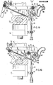
- the cutting device is provided with centering means 80, which has for its object to place the bone in the meat piece exactly in the center line of the mould, for instance according to the position of the bone as showed in fig. 11.
- Said centering means are here formed like arms 81, which are parallel to eachother, whereas one end of which are fastened to a rod 82 pivotably arranged in between a pair of levers 83 secured to a driving shaft 84.
- Said driving shaft is journalled in a frame part 85 secured to the upper mould 51 of the boning device.
- the rod 82 is further provided with a bracket 86, the free end of which is provided with a roller 87.
- the roller is guided in a cam-track 88, part of the frame 85.
- centering arms 81 are movable simultaneously into the space in between the upper and lower mould and are to be protected therefrom.
- the simultaneous movement is achieved by a linkage 89 pivotably journalled unto crank arms 90 on both driving shafts 84 of the opposite centering arms.
- One of the shafts 84 is provided with a crank arm 91 to which any suitable driving means can be connected.
- the arms 81 will be brought in the retracted second position, according to fig. 18 so the lower mould 52 can reach the upper mould undisturbed by the arms 81.
- the moulds are in the position of for instance fig. 8. ;
- the protruding arms may have any suitable form, wherein it is just necessary that the end faces thereof are positioned so that the urging action is directed to the lower mould 52 in order to have the bone centered accurately.
Landscapes
- Life Sciences & Earth Sciences (AREA)
- Engineering & Computer Science (AREA)
- Wood Science & Technology (AREA)
- Zoology (AREA)
- Food Science & Technology (AREA)
- Processing Of Meat And Fish (AREA)
- Meat, Egg Or Seafood Products (AREA)
Priority Applications (2)
| Application Number | Priority Date | Filing Date | Title |
|---|---|---|---|
| AT83200165T ATE37270T1 (de) | 1982-02-08 | 1983-01-27 | Entbeinungsvorrichtung und methode fuer entbeinung. |
| DE8383200165T DE3378014D1 (en) | 1982-02-08 | 1983-01-27 | Boning device and method for boning |
Applications Claiming Priority (6)
| Application Number | Priority Date | Filing Date | Title |
|---|---|---|---|
| NL8200469 | 1982-02-08 | ||
| NL8200469A NL8200469A (nl) | 1982-02-08 | 1982-02-08 | Uitbeeninrichting. |
| NL8201159 | 1982-03-19 | ||
| NL8201159A NL8201159A (nl) | 1982-03-19 | 1982-03-19 | Uitbeeninrichting. |
| NL8203078 | 1982-08-02 | ||
| NL8203078A NL8203078A (nl) | 1982-02-08 | 1982-08-02 | Uitbeeninrichting. |
Related Child Applications (2)
| Application Number | Title | Priority Date | Filing Date |
|---|---|---|---|
| EP87201095.4 Division-Into | 1983-01-27 | ||
| EP87202609.1 Division-Into | 1983-01-27 |
Publications (2)
| Publication Number | Publication Date |
|---|---|
| EP0086020A1 true EP0086020A1 (fr) | 1983-08-17 |
| EP0086020B1 EP0086020B1 (fr) | 1988-09-21 |
Family
ID=27352085
Family Applications (2)
| Application Number | Title | Priority Date | Filing Date |
|---|---|---|---|
| EP87202609A Ceased EP0271967A1 (fr) | 1982-02-08 | 1983-01-27 | Appareil à désosser |
| EP83200165A Expired EP0086020B1 (fr) | 1982-02-08 | 1983-01-27 | Appareil et méthode à désosser |
Family Applications Before (1)
| Application Number | Title | Priority Date | Filing Date |
|---|---|---|---|
| EP87202609A Ceased EP0271967A1 (fr) | 1982-02-08 | 1983-01-27 | Appareil à désosser |
Country Status (7)
| Country | Link |
|---|---|
| US (1) | US4577369A (fr) |
| EP (2) | EP0271967A1 (fr) |
| JP (1) | JPH0665272B2 (fr) |
| AU (2) | AU556369B2 (fr) |
| ES (1) | ES519590A0 (fr) |
| PL (1) | PL140864B1 (fr) |
| SU (1) | SU1547691A3 (fr) |
Cited By (8)
| Publication number | Priority date | Publication date | Assignee | Title |
|---|---|---|---|---|
| EP0133332A3 (en) * | 1983-07-22 | 1986-12-30 | Langen Research B.V. | Boning device |
| EP0244032A1 (fr) * | 1986-05-02 | 1987-11-04 | Stork Protecon B.V. | Dispositif de désossage de viande |
| EP0262722A1 (fr) * | 1986-09-22 | 1988-04-06 | Langen Research B.V. | Procédé et dispositif de désossage de portions de viande |
| EP0271967A1 (fr) | 1982-02-08 | 1988-06-22 | Langen Research B.V. | Appareil à désosser |
| EP0324994A1 (fr) * | 1988-01-19 | 1989-07-26 | Stork Protecon B.V. | Procédé et dispositif de désossement de viande |
| EP0324995A1 (fr) * | 1988-01-19 | 1989-07-26 | Stork Protecon B.V. | Dispositif de désossage de viande |
| EP0373682A1 (fr) * | 1988-11-09 | 1990-06-20 | Langen Research B.V. | Dispositif de désossement de portions de viande avec de moyens presseurs façonnés |
| NL1008702C2 (nl) * | 1998-03-25 | 1999-09-28 | Stork Mps Bv | Inrichting, matrijs en werkwijze voor het ontbenen van vlees. |
Families Citing this family (11)
| Publication number | Priority date | Publication date | Assignee | Title |
|---|---|---|---|---|
| JPS58501106A (ja) * | 1981-07-15 | 1983-07-14 | プロテコン ベ−・ヴェ− | 食肉の骨取りのための装置 |
| NL8200469A (nl) * | 1982-02-08 | 1983-09-01 | Langen Research | Uitbeeninrichting. |
| NL8302628A (nl) * | 1983-07-22 | 1985-02-18 | Langen Research | Uitbeeninrichting. |
| NL8702872A (nl) * | 1987-11-30 | 1989-06-16 | Ccm Beheer Bv | Uitbeeninrichting, in het bijzonder voor het verwijderen van de ribben uit een varkensbuikstuk. |
| DE3743541A1 (de) * | 1987-12-22 | 1989-07-06 | Nordischer Maschinenbau | Einrichtung zum abstreifen des fleisches von den extremitaeten von gefluegel |
| US4893378A (en) * | 1988-10-31 | 1990-01-16 | Systemate Holland B.V. | Revoving poultry thigh deboner |
| NZ243789A (en) * | 1992-07-30 | 1996-01-26 | Colin Andrew Roberts | Removing meat from bones by forcing bones through flexible collar |
| US5813905A (en) * | 1994-05-31 | 1998-09-29 | Stork Protecon-Langen B.V. | Device and apparatus for deboning halves of slaughtered animals |
| NL1000877C2 (nl) * | 1995-07-24 | 1997-01-28 | Stork Rms Bv | Werkwijze en inrichting voor het losmaken van ingewanden. |
| NL1039317C2 (en) * | 2012-01-23 | 2013-07-25 | Foodmate B V | Bone holder for meat processing equipment. |
| SE545808C2 (en) * | 2022-06-23 | 2024-02-06 | Ikea Supply Ag | A removable handle for pots and pans |
Citations (2)
| Publication number | Priority date | Publication date | Assignee | Title |
|---|---|---|---|---|
| US2897536A (en) * | 1958-04-04 | 1959-08-04 | Campbell Soup Co | Poultry boning machine |
| EP0070605A1 (fr) * | 1981-07-15 | 1983-01-26 | Protecon B.V. | Dispositif de désossage de viande |
Family Cites Families (6)
| Publication number | Priority date | Publication date | Assignee | Title |
|---|---|---|---|---|
| US3172327A (en) * | 1960-09-13 | 1965-03-09 | Templet Ind Inc | Die for trimming cast and molded objects having a three-dimensional trim-line |
| US3256764A (en) * | 1962-05-31 | 1966-06-21 | United Aircraft Corp | Rule cutting device |
| US3285715A (en) * | 1963-06-11 | 1966-11-15 | Jr William H Burkhart | Strip of flexible material having a plurality of separate metal elements mounted thereon in adjacent parallel relationship |
| US3531825A (en) * | 1967-06-14 | 1970-10-06 | Asa B Segur | Apparatus for de-boning raw poultry meat |
| DE2542909C3 (de) * | 1975-09-26 | 1979-08-02 | Lindemann Maschinenfabrik Gmbh, 4000 Duesseldorf | Schrottschere, insbesondere zur Verarbeitung von Flachmaterial |
| AU556369B2 (en) | 1982-02-08 | 1986-10-30 | Langen Research B.V. | Boning device |
-
1983
- 1983-01-25 AU AU10745/83A patent/AU556369B2/en not_active Ceased
- 1983-01-27 EP EP87202609A patent/EP0271967A1/fr not_active Ceased
- 1983-01-27 EP EP83200165A patent/EP0086020B1/fr not_active Expired
- 1983-01-31 US US06/462,395 patent/US4577369A/en not_active Expired - Lifetime
- 1983-02-07 ES ES519590A patent/ES519590A0/es active Granted
- 1983-02-07 SU SU833552492A patent/SU1547691A3/ru active
- 1983-02-07 PL PL1983240470A patent/PL140864B1/pl unknown
- 1983-02-08 JP JP58019532A patent/JPH0665272B2/ja not_active Expired - Lifetime
-
1987
- 1987-01-27 AU AU68038/87A patent/AU601964B2/en not_active Ceased
Patent Citations (2)
| Publication number | Priority date | Publication date | Assignee | Title |
|---|---|---|---|---|
| US2897536A (en) * | 1958-04-04 | 1959-08-04 | Campbell Soup Co | Poultry boning machine |
| EP0070605A1 (fr) * | 1981-07-15 | 1983-01-26 | Protecon B.V. | Dispositif de désossage de viande |
Cited By (10)
| Publication number | Priority date | Publication date | Assignee | Title |
|---|---|---|---|---|
| EP0271967A1 (fr) | 1982-02-08 | 1988-06-22 | Langen Research B.V. | Appareil à désosser |
| EP0133332A3 (en) * | 1983-07-22 | 1986-12-30 | Langen Research B.V. | Boning device |
| EP0244032A1 (fr) * | 1986-05-02 | 1987-11-04 | Stork Protecon B.V. | Dispositif de désossage de viande |
| US4779306A (en) * | 1986-05-02 | 1988-10-25 | Stork Protecon B.V. | Device for deboning meat |
| EP0262722A1 (fr) * | 1986-09-22 | 1988-04-06 | Langen Research B.V. | Procédé et dispositif de désossage de portions de viande |
| EP0324994A1 (fr) * | 1988-01-19 | 1989-07-26 | Stork Protecon B.V. | Procédé et dispositif de désossement de viande |
| EP0324995A1 (fr) * | 1988-01-19 | 1989-07-26 | Stork Protecon B.V. | Dispositif de désossage de viande |
| EP0373682A1 (fr) * | 1988-11-09 | 1990-06-20 | Langen Research B.V. | Dispositif de désossement de portions de viande avec de moyens presseurs façonnés |
| NL1008702C2 (nl) * | 1998-03-25 | 1999-09-28 | Stork Mps Bv | Inrichting, matrijs en werkwijze voor het ontbenen van vlees. |
| WO1999048374A1 (fr) * | 1998-03-25 | 1999-09-30 | Stork Mps B.V. | Dispositif, moule, et procede pour desosser la viande |
Also Published As
| Publication number | Publication date |
|---|---|
| JPS58146231A (ja) | 1983-08-31 |
| AU1074583A (en) | 1983-08-18 |
| AU601964B2 (en) | 1990-09-27 |
| PL240470A1 (en) | 1983-08-15 |
| JPH0665272B2 (ja) | 1994-08-24 |
| EP0086020B1 (fr) | 1988-09-21 |
| EP0271967A1 (fr) | 1988-06-22 |
| US4577369A (en) | 1986-03-25 |
| AU556369B2 (en) | 1986-10-30 |
| ES8400658A1 (es) | 1983-11-16 |
| ES519590A0 (es) | 1983-11-16 |
| AU6803887A (en) | 1987-04-30 |
| PL140864B1 (en) | 1987-06-30 |
| SU1547691A3 (ru) | 1990-02-28 |
Similar Documents
| Publication | Publication Date | Title |
|---|---|---|
| EP0086020A1 (fr) | Appareil et méthode à désosser | |
| US4216565A (en) | Meat stripping machine for fowl | |
| CA1289310C (fr) | Desosseuse de volailles | |
| US8408978B2 (en) | Device for processing poultry wings | |
| MX2012005072A (es) | Metodo y dispositivo para deshuesar una pierna con hueso. | |
| US12219965B2 (en) | Automated chicken deboner system and method | |
| EP0297114B1 (fr) | Dispositif pour decouper la viande en filets | |
| US6383067B1 (en) | Device for deboning of poultry parts | |
| SU1494853A3 (ru) | Устройство дл обвалки частей туш животных (его варианты) | |
| US12465058B2 (en) | Method and device for processing a carcass-part of slaughtered poultry | |
| CA1217382A (fr) | Desosseuse mecanique | |
| CA1219167A (fr) | Dispositif desosseur de viandes | |
| JPH01265846A (ja) | 家禽の四肢とくに腿またはドラムステイツクのような脚部から肉をはぎとる装置 | |
| GB2124883A (en) | Apparatus for removing meat from poultry drumsticks | |
| WO1995017825A1 (fr) | Procede et appareil pour depecer de la viande | |
| NZ204014A (en) | Device for boning pieces of meat | |
| EP0652711B1 (fr) | Procede et appareil pour desosser des pieces de boucherie | |
| JP2021000059A (ja) | 鶏のせせり肉切剥機構 | |
| EP0373682B1 (fr) | Dispositif de désossement de portions de viande avec de moyens presseurs façonnés | |
| AU592686B2 (en) | Poultry deboner | |
| SU797638A1 (ru) | Устройство дл разделки рыбы | |
| NL8203078A (nl) | Uitbeeninrichting. | |
| NZ233480A (en) | Press for removing meat from bones | |
| NZ277897A (en) | Carcass processing for the removal of whole tissue meat, first and second cutting elements forming cuts in advance of clearing action knives | |
| NL8201159A (nl) | Uitbeeninrichting. |
Legal Events
| Date | Code | Title | Description |
|---|---|---|---|
| PUAI | Public reference made under article 153(3) epc to a published international application that has entered the european phase |
Free format text: ORIGINAL CODE: 0009012 |
|
| AK | Designated contracting states |
Designated state(s): AT BE CH DE FR GB IT LI LU NL SE |
|
| 17P | Request for examination filed |
Effective date: 19840214 |
|
| ITF | It: translation for a ep patent filed | ||
| GRAA | (expected) grant |
Free format text: ORIGINAL CODE: 0009210 |
|
| AK | Designated contracting states |
Kind code of ref document: B1 Designated state(s): AT BE CH DE FR GB IT LI LU NL SE |
|
| REF | Corresponds to: |
Ref document number: 37270 Country of ref document: AT Date of ref document: 19881015 Kind code of ref document: T |
|
| REF | Corresponds to: |
Ref document number: 3378014 Country of ref document: DE Date of ref document: 19881027 |
|
| ET | Fr: translation filed | ||
| PLBE | No opposition filed within time limit |
Free format text: ORIGINAL CODE: 0009261 |
|
| STAA | Information on the status of an ep patent application or granted ep patent |
Free format text: STATUS: NO OPPOSITION FILED WITHIN TIME LIMIT |
|
| 26N | No opposition filed | ||
| PGFP | Annual fee paid to national office [announced via postgrant information from national office to epo] |
Ref country code: SE Payment date: 19901228 Year of fee payment: 9 |
|
| PG25 | Lapsed in a contracting state [announced via postgrant information from national office to epo] |
Ref country code: SE Effective date: 19920128 |
|
| REG | Reference to a national code |
Ref country code: FR Ref legal event code: TP Ref country code: FR Ref legal event code: CD |
|
| ITTA | It: last paid annual fee | ||
| PGFP | Annual fee paid to national office [announced via postgrant information from national office to epo] |
Ref country code: LU Payment date: 19930224 Year of fee payment: 11 |
|
| EPTA | Lu: last paid annual fee | ||
| PGFP | Annual fee paid to national office [announced via postgrant information from national office to epo] |
Ref country code: GB Payment date: 19931230 Year of fee payment: 12 |
|
| PGFP | Annual fee paid to national office [announced via postgrant information from national office to epo] |
Ref country code: BE Payment date: 19940121 Year of fee payment: 12 |
|
| PG25 | Lapsed in a contracting state [announced via postgrant information from national office to epo] |
Ref country code: LU Free format text: LAPSE BECAUSE OF NON-PAYMENT OF DUE FEES Effective date: 19940127 |
|
| PGFP | Annual fee paid to national office [announced via postgrant information from national office to epo] |
Ref country code: DE Payment date: 19940128 Year of fee payment: 12 |
|
| PGFP | Annual fee paid to national office [announced via postgrant information from national office to epo] |
Ref country code: CH Payment date: 19940307 Year of fee payment: 12 |
|
| PG25 | Lapsed in a contracting state [announced via postgrant information from national office to epo] |
Ref country code: GB Effective date: 19950127 |
|
| EUG | Se: european patent has lapsed |
Ref document number: 83200165.5 Effective date: 19920806 |
|
| PG25 | Lapsed in a contracting state [announced via postgrant information from national office to epo] |
Ref country code: LI Effective date: 19950131 Ref country code: BE Effective date: 19950131 Ref country code: CH Effective date: 19950131 |
|
| BERE | Be: lapsed |
Owner name: LANGEN RESEARCH B.V. Effective date: 19950131 |
|
| GBPC | Gb: european patent ceased through non-payment of renewal fee |
Effective date: 19950127 |
|
| REG | Reference to a national code |
Ref country code: CH Ref legal event code: PL |
|
| PG25 | Lapsed in a contracting state [announced via postgrant information from national office to epo] |
Ref country code: DE Effective date: 19951003 |
|
| PGFP | Annual fee paid to national office [announced via postgrant information from national office to epo] |
Ref country code: AT Payment date: 19980127 Year of fee payment: 16 |
|
| PGFP | Annual fee paid to national office [announced via postgrant information from national office to epo] |
Ref country code: NL Payment date: 19980130 Year of fee payment: 16 Ref country code: FR Payment date: 19980130 Year of fee payment: 16 |
|
| PG25 | Lapsed in a contracting state [announced via postgrant information from national office to epo] |
Ref country code: AT Free format text: LAPSE BECAUSE OF NON-PAYMENT OF DUE FEES Effective date: 19990127 |
|
| PG25 | Lapsed in a contracting state [announced via postgrant information from national office to epo] |
Ref country code: NL Free format text: LAPSE BECAUSE OF NON-PAYMENT OF DUE FEES Effective date: 19990801 |
|
| PG25 | Lapsed in a contracting state [announced via postgrant information from national office to epo] |
Ref country code: FR Free format text: LAPSE BECAUSE OF NON-PAYMENT OF DUE FEES Effective date: 19990930 |
|
| REG | Reference to a national code |
Ref country code: FR Ref legal event code: ST |