EP0101823A1 - Trockenreinigungsvorrichtung - Google Patents
Trockenreinigungsvorrichtung Download PDFInfo
- Publication number
- EP0101823A1 EP0101823A1 EP83106289A EP83106289A EP0101823A1 EP 0101823 A1 EP0101823 A1 EP 0101823A1 EP 83106289 A EP83106289 A EP 83106289A EP 83106289 A EP83106289 A EP 83106289A EP 0101823 A1 EP0101823 A1 EP 0101823A1
- Authority
- EP
- European Patent Office
- Prior art keywords
- drum
- housing
- washing
- axes
- cleaning device
- Prior art date
- Legal status (The legal status is an assumption and is not a legal conclusion. Google has not performed a legal analysis and makes no representation as to the accuracy of the status listed.)
- Granted
Links
- 238000005108 dry cleaning Methods 0.000 title claims abstract description 18
- 238000005406 washing Methods 0.000 claims abstract description 43
- 238000001035 drying Methods 0.000 claims abstract description 42
- 238000011049 filling Methods 0.000 claims abstract description 12
- 230000001154 acute effect Effects 0.000 claims abstract description 3
- 238000011068 loading method Methods 0.000 description 8
- 239000004753 textile Substances 0.000 description 8
- 239000002904 solvent Substances 0.000 description 7
- 230000032258 transport Effects 0.000 description 7
- 238000004140 cleaning Methods 0.000 description 5
- 238000000034 method Methods 0.000 description 5
- CYTYCFOTNPOANT-UHFFFAOYSA-N Perchloroethylene Chemical group ClC(Cl)=C(Cl)Cl CYTYCFOTNPOANT-UHFFFAOYSA-N 0.000 description 1
- 238000009833 condensation Methods 0.000 description 1
- 230000005494 condensation Effects 0.000 description 1
- 238000001704 evaporation Methods 0.000 description 1
- 230000008020 evaporation Effects 0.000 description 1
- 238000005429 filling process Methods 0.000 description 1
- 239000000463 material Substances 0.000 description 1
- NJPPVKZQTLUDBO-UHFFFAOYSA-N novaluron Chemical compound C1=C(Cl)C(OC(F)(F)C(OC(F)(F)F)F)=CC=C1NC(=O)NC(=O)C1=C(F)C=CC=C1F NJPPVKZQTLUDBO-UHFFFAOYSA-N 0.000 description 1
- 238000009987 spinning Methods 0.000 description 1
- 238000003892 spreading Methods 0.000 description 1
- 238000003860 storage Methods 0.000 description 1
- 229950011008 tetrachloroethylene Drugs 0.000 description 1
- 238000009834 vaporization Methods 0.000 description 1
- 230000008016 vaporization Effects 0.000 description 1
Images
Classifications
-
- D—TEXTILES; PAPER
- D06—TREATMENT OF TEXTILES OR THE LIKE; LAUNDERING; FLEXIBLE MATERIALS NOT OTHERWISE PROVIDED FOR
- D06F—LAUNDERING, DRYING, IRONING, PRESSING OR FOLDING TEXTILE ARTICLES
- D06F95/00—Laundry systems or arrangements of apparatus or machines; Mobile laundries
Definitions
- the invention relates to a dry cleaning device with washing and drying drums with tiltable housings in the frame.
- Dry cleaning devices with only one drum are predominantly used today.
- the washing process takes place in the drum first, and after it has ended and the solvent has been suctioned off, the drying process, in which the solvent adhering to the goods evaporates and is recovered by its condensation.
- Single drum machines can only be used effectively when using solvents such as perchlorethylene and FKW 113, because these solvents have only a low heat of vaporization with a low evaporation rate.
- the filling ratio in such single drum machines is between 1:18 to 1:20, which means that a drum volume of 18 to 20 liters is available for each kg of goods.
- the object of the invention is therefore to provide a dry cleaning device of the type mentioned, in which the reloading of the textiles between the washing and drying drums takes place automatically.
- this object is achieved in that the housings are pivotally mounted in the frame about axes parallel to one another and running transversely to the drum axes, and the washing drum is arranged above the drying drum in such a way that the axes of the drums pivoted at an acute angle approximately aligned with each other, and that between the discharge opening in the housing of the washing drum and the opposite filling opening in the housing of the drying drum, a conveyor connecting the openings is indicated is arranged.
- a washing process can take place while the previous contents of the washing drum are dried in the drying drum. Since both processes take about the same length, the performance can be doubled compared to single drum machines.
- the transfer of the goods after the washing process has ended into the drying drum which has meanwhile been emptied is carried out in a simple manner by inclining the drum housing, a bridging conveyor being inserted between the unloading and filling openings.
- the washing drum In its tilted position, the washing drum can also be loaded automatically in a simple manner. It is also possible to tilt the drying drum for automatic unloading, so that the dried material is emptied, for example, onto a conveyor belt or the like located in front of its unloading opening. Tilting drum housings for the purpose of emptying the drums is known.
- the washing drum housing is expediently pivotable in opposite directions about parallel axes spaced from one another, so that the washing drum housing only needs to be provided with a closable opening for the automatic filling and the automatic reloading of the goods.
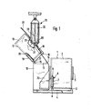
- the housing 1 of the drying drum 2 is pivotally mounted on the base frame 4 of the frame about the joint 3 located below the unloading door 5. On the side 3 opposite the joint, the housing 1 is supported on a base 6 fastened to the base frame 4.
- the piston rod 7 of the pressure medium-piston-cylinder unit 8 is hinged to the base 6, the cylinder of which is articulated to the housing 1 at point 9.
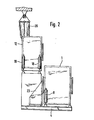
- the drying drum 2 can be pivoted about the joint 3 via the pressure medium-piston-cylinder unit 8 for the purpose of unloading and reloading. In the operating positions shown in FIGS. 1 and 2, the pressure medium piston-cylinder unit 8 clamps the housing 1 of the drying drum 2 onto the pedestal 6 of the base frame 4, so that it is firmly fixed in the frame.
- a supporting frame part 10 is connected to the base frame 4, on the raised surface 11 of which the housing 12 of the washing drum 13 is mounted.
- bases 14, 15 are fastened, which have an off Measures for supporting the bearing pins 16, 17 arranged on the underside of the housing are provided.
- the piston rods of two pressure medium - piston-cylinder units 18, 19 are pivotally mounted, their pivot axes being aligned with the bearing pins 16, 17 of the housing 12 in the operating position of the washing drum shown in FIG. 2.
- the cylinders of the pressure medium piston-cylinder units 18, 19 are pivotally connected to the housing 12 at points 20, 21 shown in FIG. 1.
- the washing drum housing 12 is provided on its side facing the drying drum 2 with a door 22 for filling and reloading.
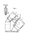
- a slide 23 is connected to the drying drum housing 1 and can be moved from its standby position pushed back in FIG. 1 into the operating position shown in FIG. 4 between the drums pivoted into their reloading position.
- the loading door 24 of the housing 1 is opened for reloading.
- the washing drum housing is first pivoted to the left in the manner shown in FIG. 1 around the pivot pin 17 by the pressure medium piston-cylinder unit 18 and the door 22 is opened.
- the goods to be cleaned are fed through a hanging track 25 running on a ceiling rail in such a way that the lower emptying opening of the transport containers 26 is located above the filling opening of the washing drum 13.
- the transport container 26 consist of bags which are open at the top and bottom and can be closed at their lower end by a clamping device. Only at the moment of unloading into the washing drum 13 the clamping device is opened by a mechanical spreading device which can be actuated, for example, by a compressed air cylinder. the washing drum 13 can be loaded automatically through the bottom opening of the transport container.
- the opening device of the transport container 13 consists of the articulated rods 27, 28, which are moved by a tension spring 29, for example, into their closed position shown in FIG. 4.
- the joint 30 of the linkages 27, 28 is moved downwards by a hydraulic cylinder.
- the textiles fall out of the latter into the washing drum 13, which rotates at an increased speed. This increase in speed during the filling process is necessary in order to obtain sufficient free space in the area of the center of the drum in which the goods can fall. Otherwise a mountain would build up in the middle of the drum, so that the goods could no longer be picked up by the drum.
- the loading door 22 is automatically closed by means not shown.
- the pressure medium-piston-cylinder unit 18 then pivots the washing drum housing into the operating position shown in FIG. 2.
- FIG 2 shows the washing drum housing 12 and the drying drum housing 1 in their operating states. While the filled textiles are cleaned in the washing drum 13, the goods cleaned in the previous washing process are dried in the drying drum 2. Further storage containers 26 with textiles to be cleaned are already waiting on the monorail.
- the pressure medium piston-cylinder units 18, 19 hold the washing drum housing firmly on the upper frame plate or the supports, while the drying drum housing 1 is held on the base frame 4 by the pressure medium piston and cylinder unit 8 is fixed.
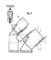
- the drying drum 2 is emptied after tilting the drying drum housing 1 in the manner shown in FIG. 3 and opening the unloading door 5, the cleaned goods expediently falling onto a conveyor belt, not shown, which automatically transports them away.
- Receiving containers can also be placed under the discharge opening of the drying drum housing 1.
- the guard drum 13 Since the cleaning time corresponds approximately to the drying time, during the unloading of the drying drum 2, the guard drum 13 is already pivoted into its reloading position, which can be seen in FIGS. 3 and 4.
- the piston-cylinder unit 19 pivots the washing drum housing 13 around the pivot pin 16.
- the hydraulic cylinder 18 holds the bearing pin 16 in its tilting bearing.
- the tilting bearing can also consist of a roller bearing instead of a bearing journal.
- the loading door 24 of the drying drum housing and the door 22 of the washing drum housing are opened.
- the slide 23 is moved into its operating position so that the transfer can take place.
- the slide 23 is expediently connected to the loading door 24 so that it takes the slide with it when it is opened.
- the drying drum 2 When filling the drying drum 2, it rotates at an increased rate Speed so that when entering the textiles they can immediately lay on the circumference of the drum and the middle area of the drum remains free for filling.
- the washing drum rotates at the cleaning speed and conveys the textiles through their inclined position from bottom to top and to the front, so that they reach the drying drum via the chute 23.
- the drying drum housing 1 is then pivoted into its operating position and the washing drum housing 12 into its filling position, which can be seen in FIG. 1. The processes are then repeated accordingly.
- All loading, transferring and unloading processes can be carried out automatically, so that personnel involved in unpleasant work can be saved and performance can be increased.
Landscapes
- Engineering & Computer Science (AREA)
- Textile Engineering (AREA)
- Cleaning In General (AREA)
- Detail Structures Of Washing Machines And Dryers (AREA)
- Treatment Of Fiber Materials (AREA)
- Drying Of Solid Materials (AREA)
- Detergent Compositions (AREA)
Abstract
Description
- Die Erfindung betrifft eine Trockenreinigungsvorrichtung mit Wasch- und Trockentrommeln mit im Gestell kippbaren Gehäusen.
- Überwiegend werden heute Trockenreinigungsvorrichtungen verwendet, die nur eine Trommel aufweisen. Bei derartigen Eintrommelmaschinen findet in der Trommel zunächst der Waschvorgang statt und nach dessen Beendigung und Absaugen des Lösemittels der Trockenvorgang, bei dem das an der Ware anhaftende Lösungsmittel verdampft und durch dessen Kondensierung wiedergewonnen wird. Eintrommelmaschinen lassen sich sinnvoll nur bei der Verwendung von Lösungsmitteln wie Perchloräthylen und FKW 113 verwenden, weil diese Lösungsmittel bei einer niedrigen Verdunstungszahl nur eine geringe Verdampfungswärme aufweisen. Das Füllverhältnis bei derartigen Eintrommelmaschinen liegt zwischen 1:18 bis 1:20, was bedeutet, daß für jedes kp Ware ein Trommelvolumen von 18 bis 20 1 zur Verfügung steht.
- Da die Leistung von Eintrommelmaschinen nur gering ist, weil während des Trocknungsvorgangs keine Reinigung erfolgen kann, ist es bekannt, Trockenreinigungsvorrichtungen zu verwenden, die über Waschtrommeln zusätzliche Trocknungstrommeln aufweisen. Bei derartigen Maschinen werden die Textilien in der Waschtrommel mit einem Füllverhältnis von 1:10 bis 1:12 im Lösemittel gewaschen bzw. gereinigt. Am Ende des Waschvorgangs wird die Ware durch Schleudern vorgetrocknet und in die Trockentrommel umgeladen. In der Trockentrommel wird das restliche an den Textilien anhaftende Lösemittel verdampft und anschließend in bekannter Weise kondensiert. Dabei erfolgt das Beladen und Entladen der Reinigung- und Trockentrommeln sowie das Umladen zwischen beiden Trommeln manuell. Die Bedienung derartiger Maschinen ist daher nicht nur personalaufwendig, es müssen im Umladebereich auch Absaugeinrichtungen für die Lösemitteldämpfe. vorgesehen werden, um die maximale Arbeitsplatzkonzentration auf den vorgeschriebenen Werten zu halten.
- Aufgabe der Erfindung ist es daher, eine Trockenreinigungsvorrichtung der eingangs angegebenen Art zu schaffen, bei der das Umladen der Textilien zwischen den Wasch- und Trockentrommeln automatisch erfolgt.
- Erfindungsgemäß wird diese Aufgabe dadurch gelöst, daß die Gehäuse um zueinander parallele, quer zu den Trommelachsen verlaufende, bodenseitig angeordnete Achsen schwenkbar im Gestell gelagert sind und die Waschtrommel derart oberhalb der Trockentrommel angeordnet ist, daß die Achsen der um einen spitzen Winkel geschwenkten Trommeln in etwa miteinander fluchten, und daß zwischen der Entladeöffnung im Gehäuse der Waschtrommel und der gegenüberliegenden Füllöffnung im Gehäuse der Trockentrommel eine die Öffnungen verbindende Fördereinrichtung angeordnet ist. Bei der erfindungsgmäßen Trockenreinigungsvorrichtung kann ein Waschvorgang erfolgen, während gleichzeitig der vorige Inhalt der Waschtrommel in der Trockentrommel getrocknet wird. Da beide Vorgänge etwa gleichlang dauern, läßt sich die Leistung gegenüber Eintrommelmaschinen verdoppeln. Die Umfüllung der Ware nach der Beendigung des Waschvorgangs in die zwischenzeitlich entleerte Trockentrommel erfolgt in einfacher Weise durch Schrägstellung der Trommelgehäuse, wobei zwischen die Entlade- und Einfüllöffnungen eine überbrückende Fördereinrichtung eingefahren wird.
- Die Waschtrommel läßt sich in ihrer gekippten Stel-lung in einfacher Weise auch automatisch beladen. Ebenso ist es möglich, die Trockentrommel zum automatischen Entladen zu kippen, so daß das getrocknete Gut beispielsweise auf ein vor dessen Entladeöffnung befindliches Förderband oder dergleichen entleert wird. Das Kippen von Trommelgehäusen zum Zwecke des Entleerens der Trommeln ist bekannt.
- Zweckmäßigerweise ist das Waschtrommelgehäuse um im Abstand voneinander angeordnete parallele Achsen gegensinnig schwenkbar, so daß zum automatischen Befüllen und zum automatischen Umladen der Ware das Waschtrommelgehäuse nur mit einer verschließbaren Öffnung versehen werden braucht.
- Weitere vorteilhafte Ausgestaltungen der Erfindung sind in den Unteransprüchen beschrieben worden. Ein Ausführungsbeispiel der Erfindung wird nachstehend anhand der Zeichnung näher erläutert. In dieser zeigt.
- Fig. 1 eine schematische Seitenansicht der Trockenreinigungsvorrichtung mit in ihre Beladestellung gekippter Waschtrommel Fig. 2 feine schematische Seitenansicht der Trockenreinigungsvorrichtung nach Fig. 1 mit in ihren Betriebsstellungen befindlichen Wasch- und Trockentrommeln,
- Fig. 3 eine schematische Seitenansicht der Trockenreinigungsvorrichtung mit in ihre Entladestellung gekippter Trockentrommel und
- Fig. 4 eine schematische Darstellung der Trockenreinigungsvorrichtung mit in ihre Umladestellungen gekippten Wasch- und Trockentrommeln.
- Das Gehäuse 1 der Trockentrommel 2 ist um das unterhalb der Entladetür 5 befindliche Gelenk 3 schwenkbar auf dem Grundrahmen 4 des Gestells gelagert. Auf der dem Gelenk gegenüberliegenden Seite 3 ist das Gehäuse 1 auf einem auf dem Grundrahmen 4 befestigten Sockel 6 abgestützt. An dem Sockel 6 ist die Kolbenstange 7 der Druckmittel-Kolben-Zylinder-Einheit 8 angelenkt, deren Zylinder im Punkt 9 gelenkig mit dem Gehäuse 1 verbunden ist. Über die Druckmittel-Kolben-Zylinder-Einheit 8 läßt sich die Trockentrommel 2 um das Gelenk 3 zum Zwecke des Entladens und Umladens verschwenken. In den aus den Fig. 1 und 2 ersichtlichen Betriebsstellungen spannt die Druckmittel-Kolben-Zylinder-Einheit 8 das Gehäuse 1 der Trockentrommel 2 auf das Podest 6 des Grundrahmens 4, so daß dieses fest im Gestell fixiert ist.
- Mit dem Grundrahmen 4 ist ein tragendes Gestellteil 10 verbunden auf dessen erhöhter Fläche 11 das Gehäuse 12 der Waschtrommel 13 gelagert ist. Auf den die erhöhte Fläche 11 bildenden Trägern oder Platten sind Sockel 14, 15 befestigt, die mit Ausnehmungen zur Abstützung der an der Unterseite des Gehäuses angeordneten Lagerzapfen 16, 17 versehen sind. An den Podesten 14, 15 sind die Kolbenstangen von zwei Druckmittel-Kolben-Zylinder-Einheiten 18, 19 schwenkbar gelagert, wobei deren Schenkachsen in der aus Fig. 2 ersichtlichen Betriebsstellung der Waschtrommel mit den Lagerzapfen 16, 17 des Gehäuses 12 fluchten. Die Zylinder der Druckmittel-Kolben-Zylinder-Einheiten 18, 19 sind in den aus Fig. 1 ersichtlich Punkten 20, 21 mit dem Gehäuse 12 schwenkbar verbunden.
- Das Waschtrommelgehäuse 12 ist auf seiner der Trockentrommel 2 zugewandten Seite mit einer Tür 22 zum Befüllen und Umladen versehen.
- Mit dem Trockentrommelgehäuse 1 ist eine Rutsche 23 verbunden, die aus ihrer in Fig. 1 zurückgeschobenen Bereitschaftsstellung in die aus Fig. 4 ersichtliche Betriebsstellung zwischen den in ihre Umladestellung geschwenkten Trommeln gefahren werden kann. Zum Umladen wird die Beladetür 24 des Gehäuses 1 geöffnet.
- Zum Beladen der Trockenreinigungsvorrichtung wird zunächst das Waschtrommelgehäuse in der aus Fig. 1 ersichtlichen Weise nach links um den Gelenkzapfen 17 durch die Druckmittel-Kolben-Zylinder-Einheit 18 geschwenkt und die Tür 22 geöffnet. Die zu reinigende Ware wird durch eine auf einer Deckenschiene laufenden Hängebahn 25 in der Weise zugeführt, daß sich die untere Entleerungsöffnung der Transportbehälter 26 oberhalb der Einfüllöffnung der Waschtrommel 13 befindet. Die Transportbehälter 26 bestehen aus Säcken, die oben und unter offen sind und an ihrem unteren Ende durch eine Klemmvorrichtung geschlossen werden können. Erst im Moment des Entladens in die Waschtrommel 13 wird die Klemmvorrichtung durch eine mechanische Spreizeinrichtung, die beisielsweise durch einen Druckluftzylinder betätigt werden kann, geöffnet. durch die bodenseitige Öffnung des Transportbehälters kann die Beladung der Waschtrommel 13 automatisch vorgenommen werden.
- Die Öffnungseinrichtung des Transportbehälters 13 besteht aus den gelenkig miteinander verbundenen Gestängen 27, 28, die durch eine Zugfeder 29 beispielsweise in ihre aus Fig. 4 ersichtliche Schließstellung bewegt werden. Zum Öffnen der Transportbehälter wird das gemeinsame Gelenk 30 der Gestänge 27, 28 durch einen Hydraulikzylinder nach unten bewegt. Nach automatischer Öffnung des Transportbehälters 26 fallen die Textilien aus diesem in die Waschtrommel 13, die mit erhöhter Drehzahl rotiert. Diese Erhöhung der Drehzahl beim Einfüllvorgang ist erforderlich, um im Bereich der Trommelmitte genügend freien Raum zu erhalten, in den die Ware fallen kann. Andernfalls würde sich in der Trommelmitte ein Berg aufbauen, so daß die Ware nicht mehr von der Trommel aufgenommen werden könnte. Nach dem Beladen der Reinigungstrommel 13 wird die Beladetür 22 durch nicht dargestellte Einrichtungen automatisch geschlossen. Die Druckmittel-Kolben-Zylinder-Einheit 18 schwenkt sodann das Waschtrommelghäuse in die aus Fig. 2 ersichtliche Betriebsstellung.
- In Fig. 2 ist das Waschtrommelgehäuse 12 und das Trockentrommelgehäuse 1 in ihren Betriebszuständen gezeigt. Während in der Waschtrommel 13 die eingefüllten Textilien gereinigt werden, erfolgt in der Trockentrommel 2 die Trocknung der im vorhergehenden Waschvorgang gereinigten Ware. An der Hängebahn befinden sich bereits weitere Vorratsbehällter 26 mit zu reinigenden Textilien in Wartestellung.
- In der aus Fig. 2 ersichtlichen Betriebsstellung halten die Druckmittel-Kolben-Zylinder-Einheiten 18, 19 das Waschtrommelgehäuse fest auf der oberen Gestellplatte bzw. den Trägern, während das Trockentrommelgehäuse 1 durch die Druckmittel-Kolben-Zylinder-Einheit 8 auf dem Grundrahmen 4 fixiert ist.
- Am Ende des Trockenvorgangs wird die Trockentrommel 2 nach Kippen des Trockentrommelgehäuses 1 in der aus Fig. 3 ersichtlichen Weise und Öffnen der Entladetür 5 entleert, wobei die gereinigte Ware zweckmäßigerweise auf ein nicht dargestelltes Transportband fällt, das diese automatisch abtransportiert. Unter die Entladeöffnung des Trockentrommelgehäuses 1 können auch Aufnahmebehälter gestellt werden.
- Da die Reinigungszeit etwa der Trockenzeit entspricht, wird während des Entladens der Trockentrommel 2 die Wachtrommel 13 bereits in ihre aus den Fig. 3 und 4 ersichtliche Umladestellung geschwenkt. Hierzu verschwenkt die Kolben-Zylinder-Einheit 19 das Waschtrommelgehäuse 13 um den Gelenkzapfen 16. Während des Schwenkvorgangs hält der Hydraulikzylinder 18 den Lagerzapfen 16 in seinem Kipplager fest. Das Kipplager kann statt aus einem Lagerzapfen auch aus einem Wälzlager bestehen.
- Nachdem der Entladevorgang abgeschlossen und die Entladetür 5 wieder geschlossen ist, werden die Beladetür 24 des Trockentrommelgehäuses und die Tür 22 des Waschtrommelgehäuses geöffnet. Gleichzeitig wird auch die.Rutsche 23 in ihre Betriebsstellung bewegt, so daß die Umfüllung erfolgen kann. Zweckmäßigerweise ist die Rutsche 23 mit der Beladetür 24 verbunden, so daß diese die Rutsche bei ihrer Öffnung mitnimmt.
- Beim Befüllen der Trockentrommel 2 dreht sich diese mit erhöhter Drehzahl, so daß sich beim Eintreten der Textilien diese sofort an dem Umfang der Trommel anlegen können und der mittlere Bereich der Trommel zum Einfüllen frei bleibt. Die Waschtrommel dreht sich mit Reinigungsdrehzahl und fördert die Textilien durch ihre Schräglage von unten nach oben und nach vorne, so daß diese über die Rutsche 23 in die Trockentrommel gelangen.
- Anschließend wird das Trockentrommelgehäuse 1 in seine Betriebsstellung und das Waschtrommelgehäuse 12 in seine aus Fig. 1 ersichtliche Befüllstellung verschwenkt. Die Vorgänge wiederholen sich sodann entsprechend.
- Sämtliche Belade-, Umfüll- und Entladevorgänge können automatisch durchgeführt werden, so daß mit unangenehmen Arbeiten beschäftigtes Personal eingespart und die Leistung erhöht werden kann.
Claims (6)
Priority Applications (1)
| Application Number | Priority Date | Filing Date | Title |
|---|---|---|---|
| AT83106289T ATE22942T1 (de) | 1982-06-28 | 1983-06-28 | Trockenreinigungsvorrichtung. |
Applications Claiming Priority (2)
| Application Number | Priority Date | Filing Date | Title |
|---|---|---|---|
| DE3224043A DE3224043C2 (de) | 1982-06-28 | 1982-06-28 | Trockenreinigungsvorrichtung |
| DE3224043 | 1982-06-28 |
Publications (2)
| Publication Number | Publication Date |
|---|---|
| EP0101823A1 true EP0101823A1 (de) | 1984-03-07 |
| EP0101823B1 EP0101823B1 (de) | 1986-10-15 |
Family
ID=6167021
Family Applications (1)
| Application Number | Title | Priority Date | Filing Date |
|---|---|---|---|
| EP83106289A Expired EP0101823B1 (de) | 1982-06-28 | 1983-06-28 | Trockenreinigungsvorrichtung |
Country Status (10)
| Country | Link |
|---|---|
| US (1) | US4499744A (de) |
| EP (1) | EP0101823B1 (de) |
| JP (1) | JPS5914882A (de) |
| AT (1) | ATE22942T1 (de) |
| CA (1) | CA1196207A (de) |
| DD (1) | DD210090A5 (de) |
| DE (1) | DE3224043C2 (de) |
| HU (1) | HU185520B (de) |
| PL (1) | PL242617A1 (de) |
| SU (1) | SU1194287A3 (de) |
Cited By (2)
| Publication number | Priority date | Publication date | Assignee | Title |
|---|---|---|---|---|
| DE3819532A1 (de) * | 1988-06-08 | 1989-12-14 | Passat Maschinenbau Gmbh | Entwaesserungszentrifuge |
| EP2891741A3 (de) * | 2013-12-26 | 2015-08-19 | Dongbu Daewoo Electronics Corporation | Trommelwaschmaschine |
Families Citing this family (7)
| Publication number | Priority date | Publication date | Assignee | Title |
|---|---|---|---|---|
| JPS60212194A (ja) * | 1984-04-06 | 1985-10-24 | 三菱重工業株式会社 | ドライクリ−ニング装置 |
| JPS6118791U (ja) * | 1984-07-11 | 1986-02-03 | 株式会社 アサヒ製作所 | 連続洗濯処理装置 |
| JPS6118790U (ja) * | 1984-07-11 | 1986-02-03 | 株式会社 アサヒ製作所 | 連続洗濯脱水装置 |
| US4972688A (en) * | 1989-06-20 | 1990-11-27 | Gpl Partnership | Vapor retaining clothes transfer system |
| US4920768A (en) * | 1989-06-20 | 1990-05-01 | Gpl Partnership | Vapor retaining clothes transfer system |
| FI109133B (fi) * | 2000-09-15 | 2002-05-31 | Lindstroem Oy | Menetelmä tekstiilien teolliseen pesemiseen tarvittavan konemoduulin valmistamiseksi ja konemoduuli |
| CN102995358B (zh) * | 2012-12-17 | 2015-04-22 | 江苏海狮机械集团有限公司 | 用于洗涤脱水机的导料装置 |
Citations (3)
| Publication number | Priority date | Publication date | Assignee | Title |
|---|---|---|---|---|
| US3742738A (en) * | 1971-07-26 | 1973-07-03 | Mc Graw Edison Co | Laundry handling system and equipment |
| GB1471980A (en) * | 1973-10-15 | 1977-04-27 | Mc Graw Edison Co | Laundry system |
| DE2704020A1 (de) * | 1977-02-01 | 1978-08-03 | Seco Maschinenbau Gmbh & Co Kg | Verfahren und vorrichtung zum chemisch-reinigen |
Family Cites Families (3)
| Publication number | Priority date | Publication date | Assignee | Title |
|---|---|---|---|---|
| DE1460997C3 (de) * | 1965-11-20 | 1974-08-08 | Fa. H. Krantz, 5100 Aachen | Waschmaschine zum Waschen und Schleudern von Textilgut |
| US3400467A (en) * | 1967-04-04 | 1968-09-10 | Western Laundry & Linen Rental | Laundry processing assembly |
| US3902337A (en) * | 1973-10-15 | 1975-09-02 | Mc Graw Edison Co | Laundry system with drying tumbler |
-
1982
- 1982-06-28 DE DE3224043A patent/DE3224043C2/de not_active Expired
-
1983
- 1983-06-21 PL PL24261783A patent/PL242617A1/xx unknown
- 1983-06-24 SU SU833610992A patent/SU1194287A3/ru active
- 1983-06-27 HU HU832313A patent/HU185520B/hu unknown
- 1983-06-27 DD DD83252413A patent/DD210090A5/de unknown
- 1983-06-27 CA CA000431220A patent/CA1196207A/en not_active Expired
- 1983-06-27 JP JP58115755A patent/JPS5914882A/ja active Pending
- 1983-06-28 AT AT83106289T patent/ATE22942T1/de not_active IP Right Cessation
- 1983-06-28 US US06/508,465 patent/US4499744A/en not_active Expired - Fee Related
- 1983-06-28 EP EP83106289A patent/EP0101823B1/de not_active Expired
Patent Citations (3)
| Publication number | Priority date | Publication date | Assignee | Title |
|---|---|---|---|---|
| US3742738A (en) * | 1971-07-26 | 1973-07-03 | Mc Graw Edison Co | Laundry handling system and equipment |
| GB1471980A (en) * | 1973-10-15 | 1977-04-27 | Mc Graw Edison Co | Laundry system |
| DE2704020A1 (de) * | 1977-02-01 | 1978-08-03 | Seco Maschinenbau Gmbh & Co Kg | Verfahren und vorrichtung zum chemisch-reinigen |
Cited By (3)
| Publication number | Priority date | Publication date | Assignee | Title |
|---|---|---|---|---|
| DE3819532A1 (de) * | 1988-06-08 | 1989-12-14 | Passat Maschinenbau Gmbh | Entwaesserungszentrifuge |
| EP2891741A3 (de) * | 2013-12-26 | 2015-08-19 | Dongbu Daewoo Electronics Corporation | Trommelwaschmaschine |
| US9493898B2 (en) | 2013-12-26 | 2016-11-15 | Dongbu Daewoo Electronics Corporation | Drum type washing machine |
Also Published As
| Publication number | Publication date |
|---|---|
| PL242617A1 (en) | 1984-02-27 |
| US4499744A (en) | 1985-02-19 |
| JPS5914882A (ja) | 1984-01-25 |
| EP0101823B1 (de) | 1986-10-15 |
| ATE22942T1 (de) | 1986-11-15 |
| DE3224043A1 (de) | 1983-12-29 |
| DD210090A5 (de) | 1984-05-30 |
| HU185520B (en) | 1985-02-28 |
| CA1196207A (en) | 1985-11-05 |
| SU1194287A3 (ru) | 1985-11-23 |
| DE3224043C2 (de) | 1984-06-28 |
Similar Documents
| Publication | Publication Date | Title |
|---|---|---|
| DE3224043C2 (de) | Trockenreinigungsvorrichtung | |
| DE69927563T2 (de) | Automatische Waage für Obst und ähnliches | |
| WO2000019039A1 (de) | Autobetonpumpe | |
| EP0486053B1 (de) | Fahrzeug zur Strandreinigung | |
| DE1456715A1 (de) | Eimerkettenfoerderer | |
| DE3312557A1 (de) | Hievkipper zum aufnehmen, liegenden transportieren und stehenden absetzen von behaeltern | |
| EP0358893A1 (de) | Hubkippvorrichtung zum Entleeren von Müllbehältern in ein Sammelfahrzeug | |
| DE2625693B2 (de) | Vorrichtung zum Fördern von Schüttgut | |
| DE4025705A1 (de) | Vorrichtung zum transportieren und entleeren von schuettgutbehaeltern | |
| DE3008090C2 (de) | ||
| DE2937255A1 (de) | Maschine zum entleeren von mit schuettgut gefuellten harassen | |
| DE19829874A1 (de) | Wäsche-Zentrifuge, insbesondere für eine automatische Waschstraße | |
| DE7537105U (de) | Foerdervorrichtung mit achsenbaugruppe, insbesondere schraegfoerderer | |
| DE2212651A1 (de) | Breitbehandlungsmaschine | |
| DE1157149B (de) | Umlauf-Haengefoerderer fuer den Transport von mit einem hakenfoermigen Aufhaengegliedversehenen Guttraegern | |
| DE4219536A1 (de) | Verfahren und Zentrifuge zum Entwaessern in Postenwaschanlagen | |
| DE2046691A1 (de) | Transportvorrichtung fur Gußstucke | |
| DE19547831C2 (de) | Müllsammelfahrzeug | |
| DE3149914C2 (de) | Transportabler Behälter für fließfähige Güter | |
| DE2524622A1 (de) | Geraet zum entleeren oben offener behaelter, insbesondere von sinkschachteimern | |
| DE2441911A1 (de) | Silo fuer schuettgueter | |
| DE1920979C (de) | Vorrichtung zum Umsetzen von als Stapel auf einer Palette aufgenommenen Waren auf eine andere Tragplatte | |
| EP0333192A2 (de) | Vorrichtung zum Entleeren von Behältern | |
| AT16527B (de) | Selbsttätige, ununterbrochen wirkende Beschickungs- oder Entleerungsvorrichtung an Vakuumtrockern. | |
| AT349995B (de) | Anbau-siloentnahmegeraet |
Legal Events
| Date | Code | Title | Description |
|---|---|---|---|
| PUAI | Public reference made under article 153(3) epc to a published international application that has entered the european phase |
Free format text: ORIGINAL CODE: 0009012 |
|
| AK | Designated contracting states |
Designated state(s): AT BE CH FR GB IT LI LU NL SE |
|
| 17P | Request for examination filed |
Effective date: 19840629 |
|
| GRAA | (expected) grant |
Free format text: ORIGINAL CODE: 0009210 |
|
| AK | Designated contracting states |
Kind code of ref document: B1 Designated state(s): AT BE CH FR GB IT LI LU NL SE |
|
| PG25 | Lapsed in a contracting state [announced via postgrant information from national office to epo] |
Ref country code: NL Effective date: 19861015 Ref country code: IT Free format text: LAPSE BECAUSE OF FAILURE TO SUBMIT A TRANSLATION OF THE DESCRIPTION OR TO PAY THE FEE WITHIN THE PRESCRIBED TIME-LIMIT;WARNING: LAPSES OF ITALIAN PATENTS WITH EFFECTIVE DATE BEFORE 2007 MAY HAVE OCCURRED AT ANY TIME BEFORE 2007. THE CORRECT EFFECTIVE DATE MAY BE DIFFERENT FROM THE ONE RECORDED. Effective date: 19861015 Ref country code: FR Free format text: THE PATENT HAS BEEN ANNULLED BY A DECISION OF A NATIONAL AUTHORITY Effective date: 19861015 Ref country code: BE Effective date: 19861015 |
|
| REF | Corresponds to: |
Ref document number: 22942 Country of ref document: AT Date of ref document: 19861115 Kind code of ref document: T |
|
| PG25 | Lapsed in a contracting state [announced via postgrant information from national office to epo] |
Ref country code: SE Effective date: 19861031 |
|
| EN | Fr: translation not filed | ||
| NLV1 | Nl: lapsed or annulled due to failure to fulfill the requirements of art. 29p and 29m of the patents act | ||
| PG25 | Lapsed in a contracting state [announced via postgrant information from national office to epo] |
Ref country code: AT Effective date: 19870628 |
|
| PG25 | Lapsed in a contracting state [announced via postgrant information from national office to epo] |
Ref country code: LU Free format text: LAPSE BECAUSE OF NON-PAYMENT OF DUE FEES Effective date: 19870630 Ref country code: LI Effective date: 19870630 Ref country code: CH Effective date: 19870630 |
|
| PLBE | No opposition filed within time limit |
Free format text: ORIGINAL CODE: 0009261 |
|
| STAA | Information on the status of an ep patent application or granted ep patent |
Free format text: STATUS: NO OPPOSITION FILED WITHIN TIME LIMIT |
|
| 26N | No opposition filed | ||
| REG | Reference to a national code |
Ref country code: CH Ref legal event code: PL |
|
| GBPC | Gb: european patent ceased through non-payment of renewal fee | ||
| PG25 | Lapsed in a contracting state [announced via postgrant information from national office to epo] |
Ref country code: GB Effective date: 19881122 |