EP0101823B1 - Trockenreinigungsvorrichtung - Google Patents
Trockenreinigungsvorrichtung Download PDFInfo
- Publication number
- EP0101823B1 EP0101823B1 EP83106289A EP83106289A EP0101823B1 EP 0101823 B1 EP0101823 B1 EP 0101823B1 EP 83106289 A EP83106289 A EP 83106289A EP 83106289 A EP83106289 A EP 83106289A EP 0101823 B1 EP0101823 B1 EP 0101823B1
- Authority
- EP
- European Patent Office
- Prior art keywords
- drum
- housing
- washing
- drying
- washing drum
- Prior art date
- Legal status (The legal status is an assumption and is not a legal conclusion. Google has not performed a legal analysis and makes no representation as to the accuracy of the status listed.)
- Expired
Links
- 238000005108 dry cleaning Methods 0.000 title claims abstract description 13
- 238000001035 drying Methods 0.000 claims abstract description 41
- 238000005406 washing Methods 0.000 claims abstract description 39
- 238000011049 filling Methods 0.000 claims abstract description 8
- 230000001154 acute effect Effects 0.000 claims abstract 2
- 238000011068 loading method Methods 0.000 description 9
- 239000002904 solvent Substances 0.000 description 7
- 239000004753 textile Substances 0.000 description 7
- 230000032258 transport Effects 0.000 description 7
- 238000004140 cleaning Methods 0.000 description 6
- 238000000034 method Methods 0.000 description 5
- 238000003860 storage Methods 0.000 description 3
- CYTYCFOTNPOANT-UHFFFAOYSA-N Perchloroethylene Chemical group ClC(Cl)=C(Cl)Cl CYTYCFOTNPOANT-UHFFFAOYSA-N 0.000 description 1
- 238000009833 condensation Methods 0.000 description 1
- 230000005494 condensation Effects 0.000 description 1
- 238000001704 evaporation Methods 0.000 description 1
- 230000008020 evaporation Effects 0.000 description 1
- 238000005429 filling process Methods 0.000 description 1
- NJPPVKZQTLUDBO-UHFFFAOYSA-N novaluron Chemical compound C1=C(Cl)C(OC(F)(F)C(OC(F)(F)F)F)=CC=C1NC(=O)NC(=O)C1=C(F)C=CC=C1F NJPPVKZQTLUDBO-UHFFFAOYSA-N 0.000 description 1
- 238000009987 spinning Methods 0.000 description 1
- 238000003892 spreading Methods 0.000 description 1
- 229950011008 tetrachloroethylene Drugs 0.000 description 1
- 238000009834 vaporization Methods 0.000 description 1
- 230000008016 vaporization Effects 0.000 description 1
Images

Classifications
-
- D—TEXTILES; PAPER
- D06—TREATMENT OF TEXTILES OR THE LIKE; LAUNDERING; FLEXIBLE MATERIALS NOT OTHERWISE PROVIDED FOR
- D06F—LAUNDERING, DRYING, IRONING, PRESSING OR FOLDING TEXTILE ARTICLES
- D06F95/00—Laundry systems or arrangements of apparatus or machines; Mobile laundries
Definitions
- the invention relates to a dry cleaning device with washing and drying drums with pivotable housings according to the preamble of claim 1.
- Dry cleaning devices with only one drum are predominantly used today.
- the washing process takes place in the drum first, and after its termination and suctioning off of the solvent, the drying process, in which the solvent adhering to the goods evaporates and is recovered by its condensation.
- Single drum machines can only be used effectively when using solvents such as perchlorethylene and FKW 113, because these solvents have only a low heat of vaporization with a low evaporation rate.
- the filling ratio in such single drum machines is between 1:18 to 1:20, which means that a drum volume of 18 to 201 is available for each kg of goods.
- GB-A-14 71 980 discloses a cleaning device in which the washing drum can be pivoted about the pivot axis 15 through a pneumatic cylinder both backwards for loading and forwards for emptying into the drying drum.
- Significant differences to the subject of the application arise in the known device from the storage of the drying drum, which is displaceable on rails by a pneumatic cylinder in the direction of the washing drum and thereby runs from an inclined ramp-shaped part of the rail in such a way that it tilts backwards and in such a way the forwardly tilted washing drum is aligned so that it can be emptied into the drying drum via an intermediate guide plate.
- the known device is complicated and expensive due to the movable storage of the drying drum and the rail arrangements caused by this. Furthermore, the known device requires more space.
- the object of the invention is therefore to provide a dry cleaning device of the known type, which has a smaller space requirement and in which the reloading pivoting of the washing and drying drums can be achieved with simple handling and with less design effort.
- the space requirement of the device according to the invention is reduced compared to the known one by dispensing with a method of the drying drum during the unloading pivoting. This is achieved in that the washing drum housing, which is mounted on an elevated surface of the housing, can be pivoted about an axis arranged on the bottom side, so that the drums can be brought into their aligned position by tilting them accordingly.
- the handling of the device is simplified in that special locks can be dispensed with because the pressure medium piston-cylinder units fix the respective pivot axes in their bearings in the normal position.
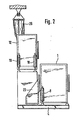
- the housing 1 of the drying drum 2 is pivotally mounted on the base frame 4 of the frame about the joint 3 located below the unloading door 5. On the side opposite the joint, the housing 1 is supported on a base 6 fastened to the base frame 4.
- the piston rod 7 of a pressure medium piston-cylinder unit 8 is articulated to the base 6, the cylinder of which is articulated to the housing 1 at point 9.
- the drying drum 2 can be pivoted about the joint 3 for the purpose of unloading and reloading.
- the pressure-piston-cylinder unit 8 clamps the housing 1 of the drying drum 2 onto the pedestal 6 of the base frame 4, so that it is firmly fixed in the frame.
- a supporting frame part 10 is connected to the base frame 4, on the raised surface 11 of which the housing 12 of the washing drum 13 is mounted.
- bases 14, 15 are fastened, which are provided with recesses for supporting the bearing pins 16, 17 arranged on the underside of the housing.
- the piston rods of two pressure medium-piston-cylinder units 18, 19 are pivotally mounted, their pivot axes being in alignment with the bearing pins 16, 17 of the housing 12 in the operating position of the washing drum shown in FIG. 2.
- the cylinders of the pressure medium piston-cylinder units 18, 19 are pivotally connected to the housing 12 in the points 20, 21 shown in FIG. 1.
- the washing drum housing 12 is provided on its side facing the drying drum 2 with a door 22 for filling and reloading.
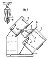
- a slide 23 is connected to the drying drum housing 1 and can be moved from its standby position pushed back in FIG. 1 into the operating position shown in FIG. 4 between the drums pivoted into their reloading position.
- the loading door 24 of the housing 1 is opened for reloading.
- the washing drum housing is first pivoted to the left about the articulated valve 17 by the pressure medium piston-cylinder unit 18 in the manner shown in FIG. 1 and the door 22 is opened.
- the goods to be cleaned are fed through a monorail 25 running on a ceiling rail in such a way that the lower emptying opening of the transport containers 26 is located above the filling opening of the washing drum 13.
- the transport container 26 consist of bags which are open at the top and bottom and can be closed at their lower end by a clamping device. Only at the moment of unloading into the washing drum 13 is the clamping device opened by a mechanical spreading device, which can be actuated, for example, by a compressed air cylinder. the washing drum 13 can be loaded automatically through the bottom opening of the transport container.
- the opening device of the transport container 13 consists of the articulated rods 27, 28, which are moved by a tension spring 29, for example, into their closed position shown in FIG. 4.
- the joint 30 of the linkages 27, 28 is moved downwards by a hydraulic cylinder.
- the textiles fall out of the latter into the washing drum 13, which rotates at an increased speed. This increase in speed during the filling process is necessary in order to obtain sufficient free space in the area of the center of the drum in which the goods can fall. Otherwise a mountain would build up in the middle of the drum, so that the goods could no longer be picked up by the drum.
- the loading door 22 is automatically closed by means not shown.
- the pressure medium-piston-cylinder unit 18 then pivots the washing drum housing into the operating position shown in FIG. 2.
- FIG 2 shows the washing drum housing 12 and the drying drum housing 1 in their operating states. While the filled textiles are cleaned in the washing drum 13, the goods cleaned in the previous washing process are dried in the drying drum 2. Further storage containers 26 with textiles to be cleaned are already waiting on the monorail.
- the pressure medium piston-cylinder units 18, 19 hold the washing drum housing firmly on the upper frame plate or the supports, while the drying drum housing 1 is held on the base frame 4 by the pressure medium piston and cylinder unit 8 is fixed.
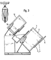
- the drying drum 2 is emptied after tilting the drying drum housing 1 in the manner shown in FIG. 3 and opening the unloading door 5, the cleaned goods expediently falling onto a conveyor belt, not shown, which automatically transports them away.
- Receiving containers can also be placed under the discharge opening of the drying drum housing 1.
- the guard drum 13 Since the cleaning time corresponds approximately to the drying time, during the unloading of the drying drum 2, the guard drum 13 is already pivoted into its reloading position, which can be seen in FIGS. 3 and 4.
- the piston-cylinder unit 19 pivots the washing drum housing 13 around the pivot pin 16.
- the hydraulic cylinder 18 holds the bearing pin 16 in its tilting bearing.
- the tilting bearing can also consist of a roller bearing instead of a bearing journal.
- the loading door 24 of the drying drum housing and the door 22 of the washing drum housing are opened.
- the slide 23 is also moved into its operating position so that the transfer can take place.
- the slide 23 with the Loading door 24 connected so that it takes the slide with it when it opens.
- the drying drum 2 When filling the drying drum 2, it rotates at an increased speed, so that when the textiles enter, they can immediately lay against the circumference of the drum and the middle area of the drum remains free for filling.
- the washing drum rotates at the cleaning speed and conveys the textiles through their inclined position from bottom to top and to the front, so that they reach the drying drum via the chute 23.
- the drying drum housing 1 is then pivoted into its operating position and the washing drum housing 12 into its filling position, which can be seen in FIG. 1. The processes are then repeated accordingly.
- All loading, transferring and unloading processes can be carried out automatically, so that personnel involved in unpleasant work can be saved and performance can be increased.
Landscapes
- Engineering & Computer Science (AREA)
- Textile Engineering (AREA)
- Cleaning In General (AREA)
- Detail Structures Of Washing Machines And Dryers (AREA)
- Treatment Of Fiber Materials (AREA)
- Drying Of Solid Materials (AREA)
- Detergent Compositions (AREA)
Priority Applications (1)
| Application Number | Priority Date | Filing Date | Title |
|---|---|---|---|
| AT83106289T ATE22942T1 (de) | 1982-06-28 | 1983-06-28 | Trockenreinigungsvorrichtung. |
Applications Claiming Priority (2)
| Application Number | Priority Date | Filing Date | Title |
|---|---|---|---|
| DE3224043A DE3224043C2 (de) | 1982-06-28 | 1982-06-28 | Trockenreinigungsvorrichtung |
| DE3224043 | 1982-06-28 |
Publications (2)
| Publication Number | Publication Date |
|---|---|
| EP0101823A1 EP0101823A1 (de) | 1984-03-07 |
| EP0101823B1 true EP0101823B1 (de) | 1986-10-15 |
Family
ID=6167021
Family Applications (1)
| Application Number | Title | Priority Date | Filing Date |
|---|---|---|---|
| EP83106289A Expired EP0101823B1 (de) | 1982-06-28 | 1983-06-28 | Trockenreinigungsvorrichtung |
Country Status (10)
| Country | Link |
|---|---|
| US (1) | US4499744A (ja) |
| EP (1) | EP0101823B1 (ja) |
| JP (1) | JPS5914882A (ja) |
| AT (1) | ATE22942T1 (ja) |
| CA (1) | CA1196207A (ja) |
| DD (1) | DD210090A5 (ja) |
| DE (1) | DE3224043C2 (ja) |
| HU (1) | HU185520B (ja) |
| PL (1) | PL242617A1 (ja) |
| SU (1) | SU1194287A3 (ja) |
Families Citing this family (9)
| Publication number | Priority date | Publication date | Assignee | Title |
|---|---|---|---|---|
| JPS60212194A (ja) * | 1984-04-06 | 1985-10-24 | 三菱重工業株式会社 | ドライクリ−ニング装置 |
| JPS6118791U (ja) * | 1984-07-11 | 1986-02-03 | 株式会社 アサヒ製作所 | 連続洗濯処理装置 |
| JPS6118790U (ja) * | 1984-07-11 | 1986-02-03 | 株式会社 アサヒ製作所 | 連続洗濯脱水装置 |
| DE3819532A1 (de) * | 1988-06-08 | 1989-12-14 | Passat Maschinenbau Gmbh | Entwaesserungszentrifuge |
| US4972688A (en) * | 1989-06-20 | 1990-11-27 | Gpl Partnership | Vapor retaining clothes transfer system |
| US4920768A (en) * | 1989-06-20 | 1990-05-01 | Gpl Partnership | Vapor retaining clothes transfer system |
| FI109133B (fi) * | 2000-09-15 | 2002-05-31 | Lindstroem Oy | Menetelmä tekstiilien teolliseen pesemiseen tarvittavan konemoduulin valmistamiseksi ja konemoduuli |
| CN102995358B (zh) * | 2012-12-17 | 2015-04-22 | 江苏海狮机械集团有限公司 | 用于洗涤脱水机的导料装置 |
| KR101568210B1 (ko) * | 2013-12-26 | 2015-11-12 | 동부대우전자 주식회사 | 드럼 세탁기 |
Family Cites Families (6)
| Publication number | Priority date | Publication date | Assignee | Title |
|---|---|---|---|---|
| DE1460997C3 (de) * | 1965-11-20 | 1974-08-08 | Fa. H. Krantz, 5100 Aachen | Waschmaschine zum Waschen und Schleudern von Textilgut |
| US3400467A (en) * | 1967-04-04 | 1968-09-10 | Western Laundry & Linen Rental | Laundry processing assembly |
| US3742738A (en) * | 1971-07-26 | 1973-07-03 | Mc Graw Edison Co | Laundry handling system and equipment |
| US3902254A (en) * | 1973-10-15 | 1975-09-02 | Mc Graw Edison Co | Laundry system with drying tumbler |
| US3902337A (en) * | 1973-10-15 | 1975-09-02 | Mc Graw Edison Co | Laundry system with drying tumbler |
| DE2704020A1 (de) * | 1977-02-01 | 1978-08-03 | Seco Maschinenbau Gmbh & Co Kg | Verfahren und vorrichtung zum chemisch-reinigen |
-
1982
- 1982-06-28 DE DE3224043A patent/DE3224043C2/de not_active Expired
-
1983
- 1983-06-21 PL PL24261783A patent/PL242617A1/xx unknown
- 1983-06-24 SU SU833610992A patent/SU1194287A3/ru active
- 1983-06-27 HU HU832313A patent/HU185520B/hu unknown
- 1983-06-27 DD DD83252413A patent/DD210090A5/de unknown
- 1983-06-27 CA CA000431220A patent/CA1196207A/en not_active Expired
- 1983-06-27 JP JP58115755A patent/JPS5914882A/ja active Pending
- 1983-06-28 AT AT83106289T patent/ATE22942T1/de not_active IP Right Cessation
- 1983-06-28 US US06/508,465 patent/US4499744A/en not_active Expired - Fee Related
- 1983-06-28 EP EP83106289A patent/EP0101823B1/de not_active Expired
Also Published As
| Publication number | Publication date |
|---|---|
| PL242617A1 (en) | 1984-02-27 |
| US4499744A (en) | 1985-02-19 |
| JPS5914882A (ja) | 1984-01-25 |
| EP0101823A1 (de) | 1984-03-07 |
| ATE22942T1 (de) | 1986-11-15 |
| DE3224043A1 (de) | 1983-12-29 |
| DD210090A5 (de) | 1984-05-30 |
| HU185520B (en) | 1985-02-28 |
| CA1196207A (en) | 1985-11-05 |
| SU1194287A3 (ru) | 1985-11-23 |
| DE3224043C2 (de) | 1984-06-28 |
Similar Documents
| Publication | Publication Date | Title |
|---|---|---|
| DE2545051A1 (de) | Muell-sammel- und transportfahrzeug | |
| DE3224043C2 (de) | Trockenreinigungsvorrichtung | |
| EP0361118A1 (de) | Kannentransportwagen | |
| DE4019104A1 (de) | Verfahren zum ausrichten, anheben und schwenken eines behaelters relativ zu einer vertikalen oeffnung | |
| EP0666209A1 (de) | Transportwagen, insbesondere Rollbehälter, mit einziehbaren Stützbeinen | |
| DE19819389A1 (de) | Lackierwerk für Rotationsdruckmaschinen | |
| DE2803132C2 (de) | Weitgehend automatisch arbeitende Vorrichtung zum beidseitigen Beschichten von Abstandhalterrahmen für Mehrscheibenisolierglas mit einer Dichtmasse und Verfahren zur Steuerung der Vorrichtung | |
| DE3312557C2 (ja) | ||
| CH647196A5 (de) | Vorrichtung zum auswechseln des formzylinders einer tiefdruck-rotationsmaschine. | |
| DE10010056B4 (de) | Druckplattenwechsler | |
| DE19720829A1 (de) | Vorrichtung für eine Spinnkanne auf einem rotierbaren Kannenteller an einer Spinnereivorbereitungsmaschine, z. B. Strecke, Karde | |
| DE2506417A1 (de) | Verfahren und vorrichtung zur zufuehrung einer leeren spulenhuelse aus einer stetigfoerdereinrichtung an die spulstelle einer textilmaschine | |
| DE1531953A1 (de) | Vorrichtung zum Entladen von Stueckgut von einer Palette und zum UEberfuehren desselben zu einem Foerderer | |
| DE2356285A1 (de) | Vorrichtung zum entwaessern von waesche | |
| DE3008090C2 (ja) | ||
| DE4035978A1 (de) | Verfahren und vorrichtung zum laden eines adapters fuer ein leiterplattenpruefgeraet | |
| DE3147653C2 (de) | "Vorrichtung zum Speichern von einer Fülleinrichtung zuzuführenden, aus gestapelten Säcken bestehenden Bündeln" | |
| EP0972728B1 (de) | Anlage für den Transport von Schüttgut | |
| DE1920979C (de) | Vorrichtung zum Umsetzen von als Stapel auf einer Palette aufgenommenen Waren auf eine andere Tragplatte | |
| DE1755253C3 (de) | Vorrichtung zum Festlegen fahrbarer Behälter auf einer Fahrzeugladefläche, insbesondere auf der Ladefläche eines Eisenbahnwagens | |
| DE19547831C2 (de) | Müllsammelfahrzeug | |
| DE2006748C3 (de) | Fahrbare Kehrmaschine mit hochschwenkbarem Schmutzkasten | |
| DE1157149B (de) | Umlauf-Haengefoerderer fuer den Transport von mit einem hakenfoermigen Aufhaengegliedversehenen Guttraegern | |
| EP0333192A2 (de) | Vorrichtung zum Entleeren von Behältern | |
| DE3320256C2 (ja) |
Legal Events
| Date | Code | Title | Description |
|---|---|---|---|
| PUAI | Public reference made under article 153(3) epc to a published international application that has entered the european phase |
Free format text: ORIGINAL CODE: 0009012 |
|
| AK | Designated contracting states |
Designated state(s): AT BE CH FR GB IT LI LU NL SE |
|
| 17P | Request for examination filed |
Effective date: 19840629 |
|
| GRAA | (expected) grant |
Free format text: ORIGINAL CODE: 0009210 |
|
| AK | Designated contracting states |
Kind code of ref document: B1 Designated state(s): AT BE CH FR GB IT LI LU NL SE |
|
| PG25 | Lapsed in a contracting state [announced via postgrant information from national office to epo] |
Ref country code: NL Effective date: 19861015 Ref country code: IT Free format text: LAPSE BECAUSE OF FAILURE TO SUBMIT A TRANSLATION OF THE DESCRIPTION OR TO PAY THE FEE WITHIN THE PRESCRIBED TIME-LIMIT;WARNING: LAPSES OF ITALIAN PATENTS WITH EFFECTIVE DATE BEFORE 2007 MAY HAVE OCCURRED AT ANY TIME BEFORE 2007. THE CORRECT EFFECTIVE DATE MAY BE DIFFERENT FROM THE ONE RECORDED. Effective date: 19861015 Ref country code: FR Free format text: THE PATENT HAS BEEN ANNULLED BY A DECISION OF A NATIONAL AUTHORITY Effective date: 19861015 Ref country code: BE Effective date: 19861015 |
|
| REF | Corresponds to: |
Ref document number: 22942 Country of ref document: AT Date of ref document: 19861115 Kind code of ref document: T |
|
| PG25 | Lapsed in a contracting state [announced via postgrant information from national office to epo] |
Ref country code: SE Effective date: 19861031 |
|
| EN | Fr: translation not filed | ||
| NLV1 | Nl: lapsed or annulled due to failure to fulfill the requirements of art. 29p and 29m of the patents act | ||
| PG25 | Lapsed in a contracting state [announced via postgrant information from national office to epo] |
Ref country code: AT Effective date: 19870628 |
|
| PG25 | Lapsed in a contracting state [announced via postgrant information from national office to epo] |
Ref country code: LU Free format text: LAPSE BECAUSE OF NON-PAYMENT OF DUE FEES Effective date: 19870630 Ref country code: LI Effective date: 19870630 Ref country code: CH Effective date: 19870630 |
|
| PLBE | No opposition filed within time limit |
Free format text: ORIGINAL CODE: 0009261 |
|
| STAA | Information on the status of an ep patent application or granted ep patent |
Free format text: STATUS: NO OPPOSITION FILED WITHIN TIME LIMIT |
|
| 26N | No opposition filed | ||
| REG | Reference to a national code |
Ref country code: CH Ref legal event code: PL |
|
| GBPC | Gb: european patent ceased through non-payment of renewal fee | ||
| PG25 | Lapsed in a contracting state [announced via postgrant information from national office to epo] |
Ref country code: GB Effective date: 19881122 |