EP0102649A1 - Appareil d'enduction du type pistolet-pulvérisation - Google Patents
Appareil d'enduction du type pistolet-pulvérisation Download PDFInfo
- Publication number
- EP0102649A1 EP0102649A1 EP83108833A EP83108833A EP0102649A1 EP 0102649 A1 EP0102649 A1 EP 0102649A1 EP 83108833 A EP83108833 A EP 83108833A EP 83108833 A EP83108833 A EP 83108833A EP 0102649 A1 EP0102649 A1 EP 0102649A1
- Authority
- EP
- European Patent Office
- Prior art keywords
- liquid
- liquid film
- paint
- web
- coating
- Prior art date
- Legal status (The legal status is an assumption and is not a legal conclusion. Google has not performed a legal analysis and makes no representation as to the accuracy of the status listed.)
- Granted
Links
- 238000000576 coating method Methods 0.000 title claims description 39
- 239000011248 coating agent Substances 0.000 title claims description 38
- 239000007921 spray Substances 0.000 title claims description 7
- 239000007788 liquid Substances 0.000 claims abstract description 134
- 239000003973 paint Substances 0.000 claims abstract description 29
- 238000004140 cleaning Methods 0.000 claims abstract description 12
- 238000005507 spraying Methods 0.000 abstract description 7
- XLYOFNOQVPJJNP-UHFFFAOYSA-N water Substances O XLYOFNOQVPJJNP-UHFFFAOYSA-N 0.000 description 17
- 239000000463 material Substances 0.000 description 8
- 238000009503 electrostatic coating Methods 0.000 description 7
- 238000000034 method Methods 0.000 description 5
- 229910052782 aluminium Inorganic materials 0.000 description 4
- XAGFODPZIPBFFR-UHFFFAOYSA-N aluminium Chemical compound [Al] XAGFODPZIPBFFR-UHFFFAOYSA-N 0.000 description 4
- 238000007610 electrostatic coating method Methods 0.000 description 4
- 239000003960 organic solvent Substances 0.000 description 4
- 230000002093 peripheral effect Effects 0.000 description 4
- OKKJLVBELUTLKV-UHFFFAOYSA-N Methanol Chemical compound OC OKKJLVBELUTLKV-UHFFFAOYSA-N 0.000 description 3
- 230000005684 electric field Effects 0.000 description 3
- 239000002904 solvent Substances 0.000 description 3
- 239000000654 additive Substances 0.000 description 2
- 230000015572 biosynthetic process Effects 0.000 description 2
- 230000007547 defect Effects 0.000 description 2
- 229910052751 metal Inorganic materials 0.000 description 2
- 239000002184 metal Substances 0.000 description 2
- 238000013508 migration Methods 0.000 description 2
- 230000005012 migration Effects 0.000 description 2
- 239000012298 atmosphere Substances 0.000 description 1
- 238000010276 construction Methods 0.000 description 1
- 230000003247 decreasing effect Effects 0.000 description 1
- 238000007599 discharging Methods 0.000 description 1
- 238000002474 experimental method Methods 0.000 description 1
- 239000000203 mixture Substances 0.000 description 1
- 239000004033 plastic Substances 0.000 description 1
- 230000001105 regulatory effect Effects 0.000 description 1
- 239000007787 solid Substances 0.000 description 1
- 239000004094 surface-active agent Substances 0.000 description 1
Images

Classifications
-
- B—PERFORMING OPERATIONS; TRANSPORTING
- B05—SPRAYING OR ATOMISING IN GENERAL; APPLYING FLUENT MATERIALS TO SURFACES, IN GENERAL
- B05B—SPRAYING APPARATUS; ATOMISING APPARATUS; NOZZLES
- B05B5/00—Electrostatic spraying apparatus; Spraying apparatus with means for charging the spray electrically; Apparatus for spraying liquids or other fluent materials by other electric means
- B05B5/08—Plant for applying liquids or other fluent materials to objects
- B05B5/14—Plant for applying liquids or other fluent materials to objects specially adapted for coating continuously moving elongated bodies, e.g. wires, strips, pipes
-
- B—PERFORMING OPERATIONS; TRANSPORTING
- B05—SPRAYING OR ATOMISING IN GENERAL; APPLYING FLUENT MATERIALS TO SURFACES, IN GENERAL
- B05B—SPRAYING APPARATUS; ATOMISING APPARATUS; NOZZLES
- B05B14/00—Arrangements for collecting, re-using or eliminating excess spraying material
-
- Y—GENERAL TAGGING OF NEW TECHNOLOGICAL DEVELOPMENTS; GENERAL TAGGING OF CROSS-SECTIONAL TECHNOLOGIES SPANNING OVER SEVERAL SECTIONS OF THE IPC; TECHNICAL SUBJECTS COVERED BY FORMER USPC CROSS-REFERENCE ART COLLECTIONS [XRACs] AND DIGESTS
- Y10—TECHNICAL SUBJECTS COVERED BY FORMER USPC
- Y10S—TECHNICAL SUBJECTS COVERED BY FORMER USPC CROSS-REFERENCE ART COLLECTIONS [XRACs] AND DIGESTS
- Y10S118/00—Coating apparatus
- Y10S118/07—Hoods
Definitions
- the present invention is directed to a spray type coating apparatus in which paint is sprayed on a vertically moving web, and more specifically cally moving web, and more specifically to means for effectively removing the oversprayed paint on both- sides of the moving web
- an electrostatic coating system was empoyoed in which the material to be coated was paint which was atomized in an electric field in a coating chamber.
- a disk-type bell-type or-gun- type electrostatic coating device was provided in the coating chamber and the materials to be coated were hung on hangers moving along a conveyor rail so that the materials were coated with paint which atomized in the electric field by the apparatus .
- Japanese Patent Application No. 28740/1980 discloses an. electrostatic coating method in which a moving web is coated with paint which is atomized in an electric field.
- Japanese Laid-Open Patent Application No. 142558/1980 discloses a technique for providing a coating pattern according to an electrostatic coaling method wherein, in order to improve a conventional circular or annular pattern, a shield plate to which a high voltage is applied and an air-curtain shaped air flow are utilized so that the coating pattern of the atomizer is rendered eliptical by the electrostatic force and by the force of the air flow.
- the coating pattern in order to form a coating which has a uniform thickness along both edge portions of the moving web which is being coated with paint according to the electrostatic coating method, the coating pattern must have a width larger than the width of the belt-shaped material. Thus, a considerable amount of overspray liquid occurs on both sides of the belt.
- Japanese Laid-Open Patent Application No. 104572 discloses a spraying method wherein a belt conveyor is confronted with the peripheral portion of the region to be sprayed so that the belt conveyor receives paint which is sprayed along the peripheral veyor receives paint which is sprayed along the peripheral portion so that the peripheral portion is protected from being sprayed with paint.
- a belt conveyor is confronted with the peripheral portion of the region to be sprayed so that the belt conveyor receives paint which is sprayed along the peripheral veyor receives paint which is sprayed along the peripheral portion so that the peripheral portion is protected from being sprayed with paint.
- the present invention provides a new and improved spray type coating apparatus which is simple in construction and operation and which overcomes all of the afore- mentioned difficulties.
- the present invention provides a new and improved spray type coating apparatus in which the spray coating operation is extremely stable and reliable for a long period of time, thereby providing a uniform coating over the entire length of the moving web.
- the present invention provides a new and improved spray type coating apparatus for spraying paint on a moving web comprising liquid film forming boards disposed on both sides of the vertically mov ⁇ ing web adjacent the both edges thereof, a plurality of parallel protrusions located on said boards and extending in a direction parallel to the direction of movement of the web, and liquid supplying means for dispensing a film of liquid downwardly over the surface of said boards for removing overspraying liquids on opposite surface of the belt.
- the spray coating apparatus illustrated in Figure 1 provides a ring-shaped coating pattern 4.
- the ring-shaped pattern 4 In order to provide a uniform thickness coating on the moving web 1 it is necessary to dimension the ring-shaped pattern 4 so that the diameter thereof is substantially greater than the width of the belt. Thus, an overspray area 5 is formed on both sides of the belt.
- a pair of liquid film forming boards 6 are located along both edges of the web 1, respectively.
- a liquid supplied from the liquid supply unit 7 forms a liquid film 8 on each board 6 which flows down the liquid filming board to intercept the oversprayed liquid-so as to con- tinuously remove the oversprayed liquid.
- the liquids flowing down the board 6 are received by any suitable receptacle 9 located at the bottom of each plate for subsequent disposal by suitable means.
- Water or a solvent such as a conventional paint thinner may be used as the liquid for forming liquid films S which flow down the boards 6 from the supply unit 7.Whenthecoating solution which is sprayed on unit 7.
- the coating solution which is sprayed on the web is a water base paint
- water can be used as the liquid film flowing down the boards.
- a solvent such as a conventional paint thinner may be used as the liquid. The formation of such liquid films which flow down the surfaces of the boards 6 located on both. sides of the web 1 is extremely effective in preventing the build up of coating material along the edges of the web as well as preventing the flow of coating material to the rear surface of the belt.
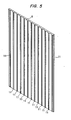
- a plurality of alon- gated protrusions 11 are formed on the surface of each liquid forming board 6 in such a manner that they extend parallel to the direction in which the liquid film flows down the board.
- a cross sectional view of the protrusion 11 is best seen in Figure 6.
- the protrusions 11 are trapezoidal in cross-section, but the configuration of the protrusions is not limited to such a configuration.
- the protrusions 11 may have a semi-circular $ cross-section.
- A. cleaning liquid supplied to each liquid supply unit 7 is uniformly spread in the widthwise direction and discharged to flow evenly down each liquid filming board 6.
- the parallel protrusions 11 formed on the surface of the liquid filming boards 6 hold the liquid therebetween which is flowing down the boards 6.
- the liquid film may be formed by using a surface active agent, water having a water-soluable organic solvent such as methanol added thereto, or an organic solvent only.
- an organic solvent such as a thinner, may. be used.
- the properties of the cleaning liquid such as composition, surface tension, viscosity and den- sity, may be suitably changed according to the purpose of use thereof and the conditions under which it is used.' It is not desirable to use an organic solvent since it may cause a fire or cause a public hazard when disposed of.
- the parallel protrusions 11 are formed on the liquid film forming board in such a manner that they are extended in the direction in which the liquid film flows downward, Accordingly, the cleaning liquid which is spread uniformly in the widthwise direction of the liquid supply unit 7 is regulated in direction and is prevented from moving in a direction perpendicular to the protrusions which damage the coating on the belt adjacent thereto.
- the liquid forming boards 6 are vertically disposed so that the liquid films 3 flow down the boards 6.
- the boards 6 may be inclined depending upon the specific conditions of use.
- a liquid film thickness is provided by the interfaced tension between the protrusions 11 and the liquid, and the liquid film is held to the boards 6 by the force of adhesion of the liquid. Accordingly, no droplets tend to separate from the liquid film.
- an inclined board operates satisfactorily similar to the case where the board is disposed vertically.
- the parallel protrusions 11 help to maintain the liquid film therebetween. Accordingly, the quantity of liquid required for forming the liquid film is considerably reduced.
- the thickness of the liquid film is made at least equal to the height of the parallel protrusions 11. That is, the provision of the parallel protrusions 11 on the surface of the liquid film forming board 6 make it possible to increase the thickness of the liquid film by considerably reducing the quantity of liquid necessary to form a liquid film. Accordingly, a stable liquid film can be formed for a long period of time without any danger of the liquid splash- ing on the moving web.
- the quantity of water may be decreased by suitably changing the properties of the water, such as viscosity and surface tension with additives.
- the equipment and additives are very expensive.
- it is necessary to change the properties of the water at all times it is necessary to provide suitable devices which are extremely intricate and expensive.
- the parallel protrusions which extend in the direction of flow of the liquid film should have a pitch of 1 5 mm, preferably 10 mm or less, and a trapezoidal cross section wherein the sides have a wiath of 5 mm, preferably 3 mm, or less, and a height of 2 mm, preferably 1 mm or less. If the pitch and the foregoing dimensions of the protrusions are increased above the foregoing values, it is difficult to form a liquid film and it is necessary to use a large quantity of liquid to form a liquid film. Furthermore, it is extremely difficult to maintain a staible liquid film without parallel protru ⁇ ' sions 11.
- the material of the liquid film forming board 6 having parallel protrusions thereon is not particularly limited, that is, it may be constructed of metal or plastic material. However, it is desirable that the liquid forming board 5 be made of metal since it is necessary for the parallel protrusions 11 to maintain the liquid film therebetween and when the oversprayed liquid meets the liquid film in an electrostatic coating method, the supply of the liquid might be interrupted.
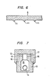
- Figure 7 discloses a sectional view of one example of a liquid supply unit 7 of the type shown in Figures 3 and 4.
- a liquid is supplied to a plenum chamber or manifold 15 through a conduit pipe 14 from a suitable liquid supply.
- the liquid thus supplied is introduced through the overflow holds 17 into chambers 16. Since the cham- b ers 16 have narrow slit-type outlets, the liquid is spread uniformly in the widthwise direction. As a result, the liquid flowing down the liquid film forming boards 6 forms a liquid film between the parallel pro- trusions 11.
- the liquid supply unit 7, as illustrated in Figure 7, is adapted to provide a liquid film on opposite sides of the liquid film forming board since the body 13 would rest on the upper surface of the board. If a liquid film is desired on only one side of the board, a modified supply unit could readily be provided.
- the cover 12 which mates with the body 13 of the supply unit 7 defines the slits for supplying the liquid from the chambers 16.
- a flat plate of SUS-304 was machined into a liquid film forming board with parallel protrusions having a pitch of 8 mm and a trapezoidal cross section having a lower side width of 1 mm, an upper side width of 0.5 mm, and a height of 1 mm.
- a flat plate of SUS-304 was machined into a liquid film forming board with para-lel protrusions having a pitch of 10 mm and a trapezoidal cross section having a lower side width of 3 mm, an upper side width of 1 mm, and a height of 1 mm.
- Water was allowed to flow down the board and when supplied at a flow rate of 4 lieters per minute it was impossible to form a liquid film.
- a stable licuid film was formed. Similar to the previous example, an overspray liquid was allowed to meet the liquid film thus formed.
- the distribution of the coating was such that that product in its entirety was free defects such as a heavy coating at the edge portions with the migration of paint to the rear surface. Furthermore, the liquid film forming board was maintained in a clean condition for a long period of use.
- the coating apparatus allows the formation of a cleaning liquid film of substantial thickness while using a relatively small quantity of cleaning liquid and no drops splash from the cleaning liquid film.
- the liquid. cleaning films are extremely stable for a long period of time, and any overspray liquids are continuously removed thereby preventing any difficulties with respect to the buildup of paint along the edge portions of the web and with respect to the paint migrating to the rear surface of the web.
- the coating according to the present invention is uniform in thickness both in the widthwise direction and in the running direction of the web and such coatings can be obtained not only on one sutface, but also on both surface of the web which is being coated by an electrostatic spray coating operation. Furthermore, the coating apparatus and the area around the coating apparatus are not contaminated by oversprayed liquids and the apparatus and atmosphere around the apparatus are maintained in a clean con- dition at all times.
Landscapes
- Electrostatic Spraying Apparatus (AREA)
- Details Or Accessories Of Spraying Plant Or Apparatus (AREA)
- Application Of Or Painting With Fluid Materials (AREA)
Applications Claiming Priority (2)
| Application Number | Priority Date | Filing Date | Title |
|---|---|---|---|
| JP135660/82U | 1982-09-07 | ||
| JP1982135660U JPS5939664U (ja) | 1982-09-07 | 1982-09-07 | 噴霧塗装装置 |
Publications (2)
| Publication Number | Publication Date |
|---|---|
| EP0102649A1 true EP0102649A1 (fr) | 1984-03-14 |
| EP0102649B1 EP0102649B1 (fr) | 1987-01-28 |
Family
ID=15156958
Family Applications (1)
| Application Number | Title | Priority Date | Filing Date |
|---|---|---|---|
| EP83108833A Expired EP0102649B1 (fr) | 1982-09-07 | 1983-09-07 | Appareil d'enduction du type pistolet-pulvérisation |
Country Status (4)
| Country | Link |
|---|---|
| US (1) | US4520755A (fr) |
| EP (1) | EP0102649B1 (fr) |
| JP (1) | JPS5939664U (fr) |
| DE (1) | DE3369472D1 (fr) |
Families Citing this family (5)
| Publication number | Priority date | Publication date | Assignee | Title |
|---|---|---|---|---|
| US4668358A (en) * | 1986-05-14 | 1987-05-26 | Motor Wheel Corporation | Method and apparatus for use in surface treatment of conveyor supported workholders |
| FI97247C (fi) * | 1994-07-01 | 1998-07-21 | Valmet Paper Machinery Inc | Spraypäällystysmenetelmä sekä spraypäällystin |
| US5849321A (en) * | 1994-07-01 | 1998-12-15 | Valmet Corporation | Method and apparatus for spray-coating a paper or board web |
| US6383568B1 (en) | 1999-08-23 | 2002-05-07 | Andrew L. Gast-Bray | Apparatus and methods for applying a coating material to sheet material |
| JP2002248388A (ja) * | 2001-02-27 | 2002-09-03 | Nippon Paint Co Ltd | ウォーターカーテン形成装置およびそれを有する塗装ブース |
Citations (3)
| Publication number | Priority date | Publication date | Assignee | Title |
|---|---|---|---|---|
| GB1529254A (en) * | 1973-02-12 | 1978-10-18 | Binks Mfg Co | Spray booths |
| GB1589853A (en) * | 1976-09-24 | 1981-05-20 | Atlas Copco Ab | Method and device for collecting surplus spray material at spray coating operations |
| EP0035905A1 (fr) * | 1980-03-11 | 1981-09-16 | Protectaire Systems Company | Cabine de pulvérisation et procédé pour son fonctionnement |
Family Cites Families (6)
| Publication number | Priority date | Publication date | Assignee | Title |
|---|---|---|---|---|
| US1746228A (en) * | 1927-01-24 | 1930-02-04 | Harry R Darling | Process and apparatus for spray coating |
| US2403018A (en) * | 1933-03-03 | 1946-07-02 | Behr Manning Corp | Manufacture of abrasives |
| US3513765A (en) * | 1969-03-26 | 1970-05-26 | Hendrik F Bok | Wet wall spray-coating chamber |
| DE2531748A1 (de) * | 1975-07-16 | 1977-02-03 | Buderus Eisenwerk | Verfahren zum eindicken von lackschlamm |
| JPS52104572A (en) * | 1976-03-01 | 1977-09-02 | Mitsubishi Heavy Ind Ltd | Spraying method |
| JPH104572A (ja) * | 1996-06-14 | 1998-01-06 | Nec Shizuoka Ltd | 無線選択呼出受信機 |
-
1982
- 1982-09-07 JP JP1982135660U patent/JPS5939664U/ja active Granted
-
1983
- 1983-09-07 US US06/530,170 patent/US4520755A/en not_active Expired - Fee Related
- 1983-09-07 EP EP83108833A patent/EP0102649B1/fr not_active Expired
- 1983-09-07 DE DE8383108833T patent/DE3369472D1/de not_active Expired
Patent Citations (3)
| Publication number | Priority date | Publication date | Assignee | Title |
|---|---|---|---|---|
| GB1529254A (en) * | 1973-02-12 | 1978-10-18 | Binks Mfg Co | Spray booths |
| GB1589853A (en) * | 1976-09-24 | 1981-05-20 | Atlas Copco Ab | Method and device for collecting surplus spray material at spray coating operations |
| EP0035905A1 (fr) * | 1980-03-11 | 1981-09-16 | Protectaire Systems Company | Cabine de pulvérisation et procédé pour son fonctionnement |
Also Published As
| Publication number | Publication date |
|---|---|
| JPS5939664U (ja) | 1984-03-13 |
| US4520755A (en) | 1985-06-04 |
| EP0102649B1 (fr) | 1987-01-28 |
| JPS6231174Y2 (fr) | 1987-08-10 |
| DE3369472D1 (en) | 1987-03-05 |
Similar Documents
| Publication | Publication Date | Title |
|---|---|---|
| JPS6138687Y2 (fr) | ||
| US4882107A (en) | Mold release coating process and apparatus using a supercritical fluid | |
| ATE40800T1 (de) | Drehglockenspritzvorrichtung zum duennen beschichten von werkstuecken mit fluessigkeit und verfahren zu ihrer anwendung. | |
| KR101426185B1 (ko) | 페인트 스프레이 부스로부터 페인트 오버스프레이를 제거하는 방법 | |
| JPH0556190B2 (fr) | ||
| US4520755A (en) | Spray type coating apparatus | |
| CA1164787A (fr) | Cabine de pistolage, et mode d'emploi connexe | |
| JPH0326370A (ja) | 液体又は溶融体の塗布方法 | |
| EP0569378A4 (fr) | Procede permettant de diriger un ecoulement allonge de materiaux de revetement, vers un substrat. | |
| JP2796826B2 (ja) | 液体又は溶融体の粒子の生成塗布方法 | |
| JP3081939B2 (ja) | 液体又は溶融体の液膜状塗布方法 | |
| JPS6346139Y2 (fr) | ||
| JPH0459948B2 (fr) | ||
| JPS58104658A (ja) | 物体を噴霧処理する装置 | |
| DE3715776C1 (de) | Verfahren und Vorrichtung zum Benetzen von festen Gegenstaenden mit Troepfchen aus fluessigen,geloesten,emulgierten oder verfluessigten Substanzen | |
| JPS6346140Y2 (fr) | ||
| JPH084136Y2 (ja) | 塗工装置 | |
| JPS5745370A (en) | Method for mixing and spraying different kind of liquid | |
| JP4623338B2 (ja) | 塗布方法 | |
| SU1199703A1 (ru) | Распылитель жидкости | |
| JPS6331570A (ja) | 走行ウエブの塗装方法 | |
| JPH1076218A (ja) | 静電塗装方法 | |
| JPS63185472A (ja) | 塗装装置 | |
| JPH0444205Y2 (fr) | ||
| JP2949725B2 (ja) | 被塗物搬送装置用洗浄装置 |
Legal Events
| Date | Code | Title | Description |
|---|---|---|---|
| PUAI | Public reference made under article 153(3) epc to a published international application that has entered the european phase |
Free format text: ORIGINAL CODE: 0009012 |
|
| AK | Designated contracting states |
Designated state(s): DE FR GB |
|
| 17P | Request for examination filed |
Effective date: 19840718 |
|
| GRAA | (expected) grant |
Free format text: ORIGINAL CODE: 0009210 |
|
| AK | Designated contracting states |
Kind code of ref document: B1 Designated state(s): DE FR GB |
|
| REF | Corresponds to: |
Ref document number: 3369472 Country of ref document: DE Date of ref document: 19870305 |
|
| ET | Fr: translation filed | ||
| PLBE | No opposition filed within time limit |
Free format text: ORIGINAL CODE: 0009261 |
|
| STAA | Information on the status of an ep patent application or granted ep patent |
Free format text: STATUS: NO OPPOSITION FILED WITHIN TIME LIMIT |
|
| 26N | No opposition filed | ||
| PG25 | Lapsed in a contracting state [announced via postgrant information from national office to epo] |
Ref country code: GB Effective date: 19890907 |
|
| GBPC | Gb: european patent ceased through non-payment of renewal fee | ||
| PG25 | Lapsed in a contracting state [announced via postgrant information from national office to epo] |
Ref country code: FR Effective date: 19900531 |
|
| PG25 | Lapsed in a contracting state [announced via postgrant information from national office to epo] |
Ref country code: DE Effective date: 19900601 |
|
| REG | Reference to a national code |
Ref country code: FR Ref legal event code: ST |