EP0121187A2 - Werkzeugträgersynchronisationsanlage für numerisch gesteuerte Geräte - Google Patents
Werkzeugträgersynchronisationsanlage für numerisch gesteuerte Geräte Download PDFInfo
- Publication number
- EP0121187A2 EP0121187A2 EP84103178A EP84103178A EP0121187A2 EP 0121187 A2 EP0121187 A2 EP 0121187A2 EP 84103178 A EP84103178 A EP 84103178A EP 84103178 A EP84103178 A EP 84103178A EP 0121187 A2 EP0121187 A2 EP 0121187A2
- Authority
- EP
- European Patent Office
- Prior art keywords
- tool
- command
- synchronizing
- circuit
- tool support
- Prior art date
- Legal status (The legal status is an assumption and is not a legal conclusion. Google has not performed a legal analysis and makes no representation as to the accuracy of the status listed.)
- Granted
Links
Images


Classifications
-
- G—PHYSICS
- G05—CONTROLLING; REGULATING
- G05B—CONTROL OR REGULATING SYSTEMS IN GENERAL; FUNCTIONAL ELEMENTS OF SUCH SYSTEMS; MONITORING OR TESTING ARRANGEMENTS FOR SUCH SYSTEMS OR ELEMENTS
- G05B19/00—Program-control systems
- G05B19/02—Program-control systems electric
- G05B19/18—Numerical control [NC], i.e. automatically operating machines, in particular machine tools, e.g. in a manufacturing environment, so as to execute positioning, movement or co-ordinated operations by means of program data in numerical form
- G05B19/19—Numerical control [NC], i.e. automatically operating machines, in particular machine tools, e.g. in a manufacturing environment, so as to execute positioning, movement or co-ordinated operations by means of program data in numerical form characterised by positioning or contouring control systems, e.g. to control position from one programmed point to another or to control movement along a programmed continuous path
- G05B19/195—Controlling the position of several slides on one axis
-
- G—PHYSICS
- G05—CONTROLLING; REGULATING
- G05B—CONTROL OR REGULATING SYSTEMS IN GENERAL; FUNCTIONAL ELEMENTS OF SUCH SYSTEMS; MONITORING OR TESTING ARRANGEMENTS FOR SUCH SYSTEMS OR ELEMENTS
- G05B19/00—Program-control systems
- G05B19/02—Program-control systems electric
- G05B19/18—Numerical control [NC], i.e. automatically operating machines, in particular machine tools, e.g. in a manufacturing environment, so as to execute positioning, movement or co-ordinated operations by means of program data in numerical form
- G05B19/416—Numerical control [NC], i.e. automatically operating machines, in particular machine tools, e.g. in a manufacturing environment, so as to execute positioning, movement or co-ordinated operations by means of program data in numerical form characterised by control of velocity, acceleration or deceleration
- G05B19/4163—Adaptive control of feed or cutting velocity
-
- G—PHYSICS
- G05—CONTROLLING; REGULATING
- G05B—CONTROL OR REGULATING SYSTEMS IN GENERAL; FUNCTIONAL ELEMENTS OF SUCH SYSTEMS; MONITORING OR TESTING ARRANGEMENTS FOR SUCH SYSTEMS OR ELEMENTS
- G05B2219/00—Program-control systems
- G05B2219/30—Nc systems
- G05B2219/41—Servomotor, servo controller till figures
- G05B2219/41249—Several slides along one axis
-
- G—PHYSICS
- G05—CONTROLLING; REGULATING
- G05B—CONTROL OR REGULATING SYSTEMS IN GENERAL; FUNCTIONAL ELEMENTS OF SUCH SYSTEMS; MONITORING OR TESTING ARRANGEMENTS FOR SUCH SYSTEMS OR ELEMENTS
- G05B2219/00—Program-control systems
- G05B2219/30—Nc systems
- G05B2219/50—Machine tool, machine tool null till machine tool work handling
- G05B2219/50008—Multiple, multi tool head, parallel machining
-
- G—PHYSICS
- G05—CONTROLLING; REGULATING
- G05B—CONTROL OR REGULATING SYSTEMS IN GENERAL; FUNCTIONAL ELEMENTS OF SUCH SYSTEMS; MONITORING OR TESTING ARRANGEMENTS FOR SUCH SYSTEMS OR ELEMENTS
- G05B2219/00—Program-control systems
- G05B2219/30—Nc systems
- G05B2219/50—Machine tool, machine tool null till machine tool work handling
- G05B2219/50235—Select tools, slides, spindles to work synchronized, independent
Definitions
- the present invention relates to tool support synchronizing systems for a numerical control apparatus.
- the invention is applicable to complex machine tools with multiple spindles.
- Figure 1 shows a tape 1 on which is recorded a program using a known numerical control language; a reading circuit 2; a buffer memory 3; a command decode processing circuit 4; a precalculation circuit 5; a control circuit 6; a spindle-shifting-amount outputting circuit 7; a pulse distribution circuit 8; a detector 11; a main-spindle rotation detector 12: a programmable controller 13 (hereinafter referred to simply as a PC); and a machine tool 14 to be controlled.
- a PC programmable controller
- the program content of the tape 1 is read by the reading circuit and temporarily stored in the buffer memory 3, and then decoded by the command decode processing circuit 4.
- Preprocessing for necessary numerical calculations is executed by the precalculation circuit 5, and the resulting data is transmitted to the control circuit 6, thereby to effect on-line control.
- the control circuit 6 outputs the data to the spindle-rotation amount outputting circuit 7 when the data is a spindle shifting command, and to the PC 13 when the data is other than a spindle shifting command. Upon the completion of execution of these commands, the control circuit outputs to the reading circuit 2 a signal for reading the next block in the program. More specifically, the amount of shifting of the spindle of the tool machine 14 is supplied to the spindle-shifting amount outputting circuit 7 for each block of the program 1 to output a pulse from the pulse distribution circuit 8, thereby to actuate the servo unit 9 for shifting the spindle using the motor 10.
- the detector 11 is mounted on the motor 10 to detect the amount of rotation of the motor 10, and the detected rotation amount is fed back to the servo unit 9 to drive the motor 10 by a predetermined amount.
- the main-spindle rotation detector 12 is mounted on the main spindle for the purpose of detecting the rotational speed of the rotating workpiece or rotating tool, and the detected rotational speed of the main spindle is fed back to the pulse distribution circuit 8 so as to make the rotational speed of the motor 10 the same as the rotational speed of the main spindle.
- the PC 13 is a sequencer used for controlling operations except for the spindle shaft shifting of the tool machine 14 such as oil-pressure control, exchange of tools, and auxiliary control of the spindle. Signals are transmitted between the programmable controller 13 and the control circuit 6 to effect such control operations.
- FIG. 2 the conventional synchronizing system for a numerical control apparatus (hereinafter referred to simply as an NC apparatus) having two tool supports as the tool machine 14 is shown.
- NC apparatus numerical control apparatus
- lA, 2A, 3A, 4A, 5A, 6A, 7A, 8A, 9A, 10A, 11A and 13A respectively designate a work program, a reading circuit, buffer memory, a command decode processing circuit, a precalculation circuit, a control circuit, a spindle-shifting-amount outputting circuit, a pulse distribution circuit, a servo unit, a motor, a detector, and a PC of a first tool support.
- 1B, 2B, 3B, 4B, 5B, 6B, 10B, 11B and 13B respectively designate a working program, a reading circuit, a buffer memory, a command decode processing circuit, a precalculation circuit, a control circuit, a spindle-shifting-amount outputting circuit, a pulse distribution circuit, a servo unit, a motor, a detector, and a PC of a second tool support.
- M10 designates the synchronizing command.
- the first and second work programs for the tool supports are shown in left- and right-hand columns, respectively, of the Table.
- the work program for the first tool support is started simultaneously with the program for the second.tool support, and the sequence number (N003) of the work program for the second tool support is synchronized (N007) of the work program for the first tool support.
- the sequence number (NO11) of the work program for the second tool support is synchronized with the sequence number (N012) of the work program for the first tool support.
- Fig. 3 shows a timing chart for the execution of the work programs in Table 1.
- a numerical value subsequent to the M command is converted to BCD code and outputted from the control circuits 6A and 6B to the PCs 13A and 13B.
- the next work program is executed after receiving a completion signal from the PCs 13A and 13B. Therefore, the synchronizing command M10 is also outputted from the control circuit 6A or 6B to the PC 13A or PC 13B.
- the PCs 13A and 13B are synchronized with each other in such a manner that one of the PCs 13A and 13B does not output a completion signal to the control circuit during the period from receipt of the synchronizing command M10 to the receipt of the synchronizing signal M10 by the other PC.
- a relay circuit of the PCs 13A and 13B is shown.
- M10A and M10B are relays actuated in accordance with the BCD code decoded from the synchronizing command M10.
- FINA and FINB are signals fed back to the control circuits 6A and 6B, respectively, of F ig. 2 as completion signals.
- the FINA and FINB signals are used for obtaining synchronization of the actuation of the relays M10A and M10B. Further in Fig.
- MFA and MFB are control signals outputted from the control circuits 6A and 6B, respectively, which are low-truth signals outputted from the control circuits slightly later than the BCD code of the M command and the completion signals FINA and FINB from the PCs 13A and PC 13B.
- the auxiliary command (M command) is utilized, and the PCs 13A and 13B effect synchronization control in response to the M command.
- M command auxiliary command
- An object of-the present invention is at least partially to eliminate the above-mentioned disadvantages of the conventional synchronizing system and to provide precise synchronization of the start of a particular block of a work program.
- Another object of the present invention is to provide a tool support synchronizing system in which a plurality of tool supports can be operated simultaneously without interference.
- a further object of the present invention is to provide a system in which a synchronizing command code can be easily discriminated from a work program.
- a particular command code used for synchronization and a synchronization controlling circuit is adapted to read this command code and process it with precise synchronization by programing a synchronizing command at the portion requiring synchronization.
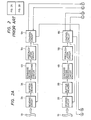
- Fig. 5 is a block diagram showing a preferred embodiment of a numerical control apparatus of the invention, in which 6C denotes a synchronization controlling circuit, a detailed example of which is shown in Fig. 6.
- 6C denotes a synchronization controlling circuit, a detailed example of which is shown in Fig. 6.
- a synchronizing command composed of one character or symbol, such as "!, is used, which synchronizing command is not used in the conventional work program.
- T 1 is an input terminal for receiving the pulse-like signal of the synchronizing command "! for the work program of the first tool support outputted from the command decoding circuit 4A in Fig. 5
- T 2 is an input terminal receiving the pulse-like signal of the synchronizing command "! of the work program of the second tool support outputted from the command decoding circuit 4B in Fig. 5
- T 3 and T 4 are output terminals for the synchronization controlling signals outputted to the control circuits 6A and 6B of Fig. 5.
- a "0" on the output terminals T 3 and T 4 means execution and a "1" means awaiting execution.
- the pulse-like signal is applied to the input terminal T 2 from the command decoding processing circuit 4B in Fig. 5 by the synchronizing command "! of the sequence number (N003) of the work program of the second tool support.
- the terminal T l is in the OFF-state, and therefore the AND gate AND 2 outputs a "1" and the flip-flop F 2 is set thereby to make the output Q equal to "1".
- the output T 3 of the flip-flop F 3 is "0" and the work program of the first tool support is being executed so that the AND gate AND 5 outputs a "1" and the flip-flop F 4 is set.
- the signal on the output terminal T 4 is thus set to "1", thereby to place the execution of the work program of the second tool support in the waiting state.
- the work program of the first tool post is sequentially executed up to the sequence number (N007), whereupon the pulse-like signal is applied to the terminal T1 of Fig. 6 from the command decoding processing circuit 4A of Fig. 5 by the synchronizing command "1".
- the signal on the terminal T l is ON
- the signal on the terminal T 2 is OFF so that the AND gate AND 1 outputs a "1" and the flip-flop F 1 is set, thereby to output from the terminal Q thereof a "1".
- the output T 4 of the flip-flop F 4 is a "1" and the work program for the second tool support is held in the waiting state so that the AND gate AND 3 outputs a "0", the AND gate AND 4 outputs a "1”, and the flip-flop F 4 is reset so that its output T 4 is a "0", thereby releasing the waiting state of the work program of the second tool post.
- the synchronization waiting command is programmed in the work program for the first tool post prior to the work program for the second tool post.
- synchronization control can be performed by having one of the two tool supports put in a waiting state and then starting its operation from a desired time instant in synchronism with the other.
- Fig. 7 an embodiment of the command decoding circuit 4A is shown.
- the code pattern "! is supplied to the input terminal T 5 of the coincidences-circuit, to the other terminal T 6 thereof of which the work program code inputted from the buffer memories 3A and 3B in Fig. 5 is applied.
- the coincidence circuit outputs "1" to the terminal T 7 upon coincidence of the two inputs, and outputs "1" to the terminal T 8 when coincidence is not established.
- the outputs of the flip-flops F 5 and F 6 and the AND gate AND 7 are "1" during the synchronizataion period of the clock signal applied to the input terminal CL of the flip-flop F 5 and F 6 when the output from the terminal T 7 becomes "1".
- Such can be realized by a simple circuit composed of a single AND gate.
- the synchronizing command code " ! " is used as a synchronizing command, but the present invention is not limited to any particular character or symbol, and a symbol such as "#" which is distinctive from the others used in the work program can be used. Further, the number of tool supports may be more than two.
- the present invention has an advantage that initiation of blocks of the work program can be precisely synchronized with the initiation of other program blocks since a code composed of a single character or symbol is used as a synchronizing command, a control circuit is provided with a synchronizing controller, and each tool support is driven in accordance with the work program after the synchronizing command within each work program is detected.
- work programs for a plurality of tool supports can be independently and simultaneously executed and the execution of a particular work block can be initiated at a designated portion within the programs.
Landscapes
- Engineering & Computer Science (AREA)
- Human Computer Interaction (AREA)
- Manufacturing & Machinery (AREA)
- Physics & Mathematics (AREA)
- General Physics & Mathematics (AREA)
- Automation & Control Theory (AREA)
- Numerical Control (AREA)
Applications Claiming Priority (2)
| Application Number | Priority Date | Filing Date | Title |
|---|---|---|---|
| JP58047478A JPS59172013A (ja) | 1983-03-22 | 1983-03-22 | 数値制御装置の刃物台同期方式 |
| JP47478/83 | 1983-03-22 |
Publications (4)
| Publication Number | Publication Date |
|---|---|
| EP0121187A2 true EP0121187A2 (de) | 1984-10-10 |
| EP0121187A3 EP0121187A3 (en) | 1986-09-03 |
| EP0121187B1 EP0121187B1 (de) | 1990-07-18 |
| EP0121187B2 EP0121187B2 (de) | 1994-11-17 |
Family
ID=12776242
Family Applications (1)
| Application Number | Title | Priority Date | Filing Date |
|---|---|---|---|
| EP84103178A Expired - Lifetime EP0121187B2 (de) | 1983-03-22 | 1984-03-22 | Werkzeugträgersynchronisationsanlage für numerisch gesteuerte Geräte |
Country Status (4)
| Country | Link |
|---|---|
| US (1) | US4631684A (de) |
| EP (1) | EP0121187B2 (de) |
| JP (1) | JPS59172013A (de) |
| DE (1) | DE3482718D1 (de) |
Cited By (3)
| Publication number | Priority date | Publication date | Assignee | Title |
|---|---|---|---|---|
| DE3627658A1 (de) * | 1985-08-15 | 1987-02-26 | Mitsubishi Electric Corp | Numerische steuervorrichtung fuer zwei werkzeuge |
| US5097575A (en) * | 1987-04-17 | 1992-03-24 | Yamazaki Mazak Corporation | Complex machining machine tool |
| EP0223857B1 (de) * | 1985-05-18 | 1993-02-03 | Fanuc Ltd. | Kompilierungsverfahren von numerisch gesteuerten programmen für eine vier-achsen-drehbank |
Families Citing this family (18)
| Publication number | Priority date | Publication date | Assignee | Title |
|---|---|---|---|---|
| JPS62237504A (ja) * | 1986-04-08 | 1987-10-17 | Fanuc Ltd | 数値制御装置 |
| JPH0769729B2 (ja) * | 1987-01-28 | 1995-07-31 | オークマ株式会社 | 複数可動部材を有する工作機械の数値制御装置における同期待合せ方式 |
| US5175914A (en) * | 1987-04-28 | 1993-01-05 | Yamazaki Mazak Corporation | Machine tool having dual spindles and tool rests |
| JP2590336B2 (ja) * | 1987-06-22 | 1997-03-12 | 三菱電機株式会社 | 制御プログラム表示装置 |
| JPS6453208A (en) * | 1987-08-24 | 1989-03-01 | Toshiba Machine Co Ltd | Parallel synchronization control system for machine tool control system |
| JP2735209B2 (ja) * | 1988-02-02 | 1998-04-02 | 三菱電機株式会社 | 数値制御装置 |
| JPH01205901A (ja) * | 1988-02-09 | 1989-08-18 | Yamazaki Mazak Corp | 複合加工工作機械における加工制御方法 |
| JP2534305B2 (ja) * | 1988-03-09 | 1996-09-11 | ファナック株式会社 | 数値制御装置 |
| US5225989A (en) * | 1988-05-19 | 1993-07-06 | Fanuc Ltd. | Apparatus and method for performing simultaneous control of control axes of a machine tool |
| JP2895071B2 (ja) * | 1988-10-11 | 1999-05-24 | ファナック株式会社 | Nc加工方法 |
| EP0385459A3 (de) * | 1989-03-02 | 1990-11-14 | Toyoda Koki Kabushiki Kaisha | Gerät zur Synchronisierkontrolle |
| JP2692011B2 (ja) * | 1990-02-09 | 1997-12-17 | 三菱電機株式会社 | 数値制御自動プログラミング装置 |
| US5222017A (en) * | 1990-11-23 | 1993-06-22 | The University Of British Columbia | Control system to synchronize slave computers |
| JP2820185B2 (ja) * | 1993-01-21 | 1998-11-05 | 三菱電機株式会社 | 複数モータの制御方法および制御システム |
| US5459915A (en) * | 1994-04-15 | 1995-10-24 | Devlieg-Bullard, Inc. | High accuracy machining station for a multiple spindle rotary indexing machine tool |
| JPH08161022A (ja) * | 1994-12-07 | 1996-06-21 | Fanuc Ltd | Cncの多系統待ち合わせ方式 |
| GB2375060B (en) * | 1997-09-12 | 2003-01-29 | Bridgeport Machines Ltd | Lifting and lowering mechanism for use with a tool carousel wheel |
| JP6916234B2 (ja) * | 2018-03-30 | 2021-08-11 | ファナック株式会社 | プログラム作成装置 |
Family Cites Families (4)
| Publication number | Priority date | Publication date | Assignee | Title |
|---|---|---|---|---|
| NL7511705A (nl) * | 1975-10-06 | 1977-04-12 | Philips Nv | Numerieke besturing voor een multigereedschap- machine. |
| US4163183A (en) * | 1975-10-28 | 1979-07-31 | Unimation, Inc. | Programmable automatic assembly system |
| JPS5731003A (en) * | 1980-08-01 | 1982-02-19 | Fanuc Ltd | Numerical control system |
| US4414495A (en) * | 1981-10-27 | 1983-11-08 | Kashifuji Works, Ltd. | Synchronism equipment for gear cutting machines |
-
1983
- 1983-03-22 JP JP58047478A patent/JPS59172013A/ja active Pending
-
1984
- 1984-03-22 EP EP84103178A patent/EP0121187B2/de not_active Expired - Lifetime
- 1984-03-22 US US06/592,205 patent/US4631684A/en not_active Expired - Lifetime
- 1984-03-22 DE DE8484103178T patent/DE3482718D1/de not_active Expired - Lifetime
Cited By (3)
| Publication number | Priority date | Publication date | Assignee | Title |
|---|---|---|---|---|
| EP0223857B1 (de) * | 1985-05-18 | 1993-02-03 | Fanuc Ltd. | Kompilierungsverfahren von numerisch gesteuerten programmen für eine vier-achsen-drehbank |
| DE3627658A1 (de) * | 1985-08-15 | 1987-02-26 | Mitsubishi Electric Corp | Numerische steuervorrichtung fuer zwei werkzeuge |
| US5097575A (en) * | 1987-04-17 | 1992-03-24 | Yamazaki Mazak Corporation | Complex machining machine tool |
Also Published As
| Publication number | Publication date |
|---|---|
| EP0121187B1 (de) | 1990-07-18 |
| EP0121187A3 (en) | 1986-09-03 |
| US4631684A (en) | 1986-12-23 |
| EP0121187B2 (de) | 1994-11-17 |
| JPS59172013A (ja) | 1984-09-28 |
| DE3482718D1 (de) | 1990-08-23 |
Similar Documents
| Publication | Publication Date | Title |
|---|---|---|
| EP0121187B1 (de) | Werkzeugträgersynchronisationsanlage für numerisch gesteuerte Geräte | |
| US5157595A (en) | Distributed logic control system and method | |
| US4631465A (en) | Tool display system of automatic tool changing apparatus | |
| US4590572A (en) | System for modifying a synchronized control program for plural tool bases by adding standby data | |
| EP0089193B1 (de) | Verfahren und Gerät zum Anzeigen von Leiterdiagrammen | |
| US4197490A (en) | Numerical control system for a machine tool having a plurality of saddles | |
| US20090271017A1 (en) | Machine tool and its program conversion method | |
| EP0025666A2 (de) | Verfahren und System zur numerischen Steuerung | |
| EP0327285B1 (de) | Numerische Steuerungseinrichtung | |
| EP0373224A1 (de) | Numerische steuerung | |
| EP0120473B1 (de) | Numerisch gesteuertes Gerät für Werkzeuge | |
| GB2083247A (en) | A programmable machine | |
| US5189604A (en) | Distributed logic control system and method | |
| JPS60193012A (ja) | 数値制御装置における刃物台同期方法 | |
| US4090120A (en) | Method and means for controlling energization by commands | |
| KR910007052B1 (ko) | 수치제어장치 | |
| EP0092312B1 (de) | Verfahren und Gerät zum Anzeigen von Leiterdiagrammen | |
| JPS6149206A (ja) | 工程運転方法 | |
| EP0328649A1 (de) | Gerät zur verarbeitung des mst-funktionsbefehlscodes | |
| JP2649801B2 (ja) | 数値制御装置における表示切換方法 | |
| JPS626245B2 (de) | ||
| JPS63136107A (ja) | Ncデ−タ入力制御装置 | |
| JPS603926B2 (ja) | 放電加工制御方法 | |
| JP3849100B2 (ja) | 同期動作制御ic | |
| JPH01100607A (ja) | 数値制御装置 |
Legal Events
| Date | Code | Title | Description |
|---|---|---|---|
| PUAI | Public reference made under article 153(3) epc to a published international application that has entered the european phase |
Free format text: ORIGINAL CODE: 0009012 |
|
| AK | Designated contracting states |
Designated state(s): DE FR GB |
|
| PUAL | Search report despatched |
Free format text: ORIGINAL CODE: 0009013 |
|
| AK | Designated contracting states |
Kind code of ref document: A3 Designated state(s): DE FR GB |
|
| 17P | Request for examination filed |
Effective date: 19870302 |
|
| 17Q | First examination report despatched |
Effective date: 19880902 |
|
| GRAA | (expected) grant |
Free format text: ORIGINAL CODE: 0009210 |
|
| AK | Designated contracting states |
Kind code of ref document: B1 Designated state(s): DE FR GB |
|
| REF | Corresponds to: |
Ref document number: 3482718 Country of ref document: DE Date of ref document: 19900823 |
|
| ET | Fr: translation filed | ||
| PLBI | Opposition filed |
Free format text: ORIGINAL CODE: 0009260 |
|
| 26 | Opposition filed |
Opponent name: ROBERT BOSCH GMBH Effective date: 19910418 |
|
| PGFP | Annual fee paid to national office [announced via postgrant information from national office to epo] |
Ref country code: FR Payment date: 19930309 Year of fee payment: 10 |
|
| PGFP | Annual fee paid to national office [announced via postgrant information from national office to epo] |
Ref country code: GB Payment date: 19930312 Year of fee payment: 10 |
|
| PG25 | Lapsed in a contracting state [announced via postgrant information from national office to epo] |
Ref country code: GB Effective date: 19940322 |
|
| PGFP | Annual fee paid to national office [announced via postgrant information from national office to epo] |
Ref country code: DE Payment date: 19940323 Year of fee payment: 11 |
|
| PUAH | Patent maintained in amended form |
Free format text: ORIGINAL CODE: 0009272 |
|
| STAA | Information on the status of an ep patent application or granted ep patent |
Free format text: STATUS: PATENT MAINTAINED AS AMENDED |
|
| GBPC | Gb: european patent ceased through non-payment of renewal fee |
Effective date: 19940322 |
|
| 27A | Patent maintained in amended form |
Effective date: 19941117 |
|
| AK | Designated contracting states |
Kind code of ref document: B2 Designated state(s): DE FR GB |
|
| PG25 | Lapsed in a contracting state [announced via postgrant information from national office to epo] |
Ref country code: FR Effective date: 19941130 |
|
| REG | Reference to a national code |
Ref country code: FR Ref legal event code: ST |
|
| EN3 | Fr: translation not filed ** decision concerning opposition | ||
| PG25 | Lapsed in a contracting state [announced via postgrant information from national office to epo] |
Ref country code: DE Effective date: 19951201 |