EP0128763A2 - Positionierungssystem für Roboter - Google Patents
Positionierungssystem für Roboter Download PDFInfo
- Publication number
- EP0128763A2 EP0128763A2 EP84303906A EP84303906A EP0128763A2 EP 0128763 A2 EP0128763 A2 EP 0128763A2 EP 84303906 A EP84303906 A EP 84303906A EP 84303906 A EP84303906 A EP 84303906A EP 0128763 A2 EP0128763 A2 EP 0128763A2
- Authority
- EP
- European Patent Office
- Prior art keywords
- arm members
- workpiece
- movement
- arm
- positioning system
- Prior art date
- Legal status (The legal status is an assumption and is not a legal conclusion. Google has not performed a legal analysis and makes no representation as to the accuracy of the status listed.)
- Ceased
Links
Images


Classifications
-
- B—PERFORMING OPERATIONS; TRANSPORTING
- B25—HAND TOOLS; PORTABLE POWER-DRIVEN TOOLS; MANIPULATORS
- B25J—MANIPULATORS; CHAMBERS PROVIDED WITH MANIPULATION DEVICES
- B25J9/00—Program-controlled manipulators
- B25J9/16—Program controls
- B25J9/1679—Program controls characterised by the tasks executed
- B25J9/1692—Calibration of manipulator
-
- B—PERFORMING OPERATIONS; TRANSPORTING
- B25—HAND TOOLS; PORTABLE POWER-DRIVEN TOOLS; MANIPULATORS
- B25J—MANIPULATORS; CHAMBERS PROVIDED WITH MANIPULATION DEVICES
- B25J13/00—Controls for manipulators
- B25J13/08—Controls for manipulators by means of sensing devices, e.g. viewing or touching devices
-
- B—PERFORMING OPERATIONS; TRANSPORTING
- B25—HAND TOOLS; PORTABLE POWER-DRIVEN TOOLS; MANIPULATORS
- B25J—MANIPULATORS; CHAMBERS PROVIDED WITH MANIPULATION DEVICES
- B25J13/00—Controls for manipulators
- B25J13/08—Controls for manipulators by means of sensing devices, e.g. viewing or touching devices
- B25J13/088—Controls for manipulators by means of sensing devices, e.g. viewing or touching devices with position, velocity or acceleration sensors
-
- B—PERFORMING OPERATIONS; TRANSPORTING
- B25—HAND TOOLS; PORTABLE POWER-DRIVEN TOOLS; MANIPULATORS
- B25J—MANIPULATORS; CHAMBERS PROVIDED WITH MANIPULATION DEVICES
- B25J15/00—Gripping heads and other end effectors
- B25J15/0095—Gripping heads and other end effectors with an external support, i.e. a support which does not belong to the manipulator or the object to be gripped, e.g. for maintaining the gripping head in an accurate position, guiding it or preventing vibrations
-
- B—PERFORMING OPERATIONS; TRANSPORTING
- B25—HAND TOOLS; PORTABLE POWER-DRIVEN TOOLS; MANIPULATORS
- B25J—MANIPULATORS; CHAMBERS PROVIDED WITH MANIPULATION DEVICES
- B25J19/00—Accessories fitted to manipulators, e.g. for monitoring, for viewing; Safety devices combined with or specially adapted for use in connection with manipulators
- B25J19/0004—Braking devices
-
- B—PERFORMING OPERATIONS; TRANSPORTING
- B25—HAND TOOLS; PORTABLE POWER-DRIVEN TOOLS; MANIPULATORS
- B25J—MANIPULATORS; CHAMBERS PROVIDED WITH MANIPULATION DEVICES
- B25J9/00—Program-controlled manipulators
- B25J9/02—Program-controlled manipulators characterised by movement of the arms, e.g. cartesian coordinate type
- B25J9/04—Program-controlled manipulators characterised by movement of the arms, e.g. cartesian coordinate type by rotating at least one arm, excluding the head movement itself, e.g. cylindrical coordinate type or polar coordinate type
- B25J9/046—Revolute coordinate type
-
- B—PERFORMING OPERATIONS; TRANSPORTING
- B25—HAND TOOLS; PORTABLE POWER-DRIVEN TOOLS; MANIPULATORS
- B25J—MANIPULATORS; CHAMBERS PROVIDED WITH MANIPULATION DEVICES
- B25J9/00—Program-controlled manipulators
- B25J9/16—Program controls
- B25J9/1602—Program controls characterised by the control system, structure, architecture
- B25J9/161—Hardware, e.g. neural networks, fuzzy logic, interfaces, processor
-
- G—PHYSICS
- G05—CONTROLLING; REGULATING
- G05B—CONTROL OR REGULATING SYSTEMS IN GENERAL; FUNCTIONAL ELEMENTS OF SUCH SYSTEMS; MONITORING OR TESTING ARRANGEMENTS FOR SUCH SYSTEMS OR ELEMENTS
- G05B2219/00—Program-control systems
- G05B2219/30—Nc systems
- G05B2219/37—Measurements
- G05B2219/37134—Gyroscope
-
- G—PHYSICS
- G05—CONTROLLING; REGULATING
- G05B—CONTROL OR REGULATING SYSTEMS IN GENERAL; FUNCTIONAL ELEMENTS OF SUCH SYSTEMS; MONITORING OR TESTING ARRANGEMENTS FOR SUCH SYSTEMS OR ELEMENTS
- G05B2219/00—Program-control systems
- G05B2219/30—Nc systems
- G05B2219/37—Measurements
- G05B2219/37404—Orientation of workpiece or tool, surface sensor
-
- G—PHYSICS
- G05—CONTROLLING; REGULATING
- G05B—CONTROL OR REGULATING SYSTEMS IN GENERAL; FUNCTIONAL ELEMENTS OF SUCH SYSTEMS; MONITORING OR TESTING ARRANGEMENTS FOR SUCH SYSTEMS OR ELEMENTS
- G05B2219/00—Program-control systems
- G05B2219/30—Nc systems
- G05B2219/39—Robotics, robotics to robotics hand
- G05B2219/39002—Move tip of arm on straight line
-
- G—PHYSICS
- G05—CONTROLLING; REGULATING
- G05B—CONTROL OR REGULATING SYSTEMS IN GENERAL; FUNCTIONAL ELEMENTS OF SUCH SYSTEMS; MONITORING OR TESTING ARRANGEMENTS FOR SUCH SYSTEMS OR ELEMENTS
- G05B2219/00—Program-control systems
- G05B2219/30—Nc systems
- G05B2219/39—Robotics, robotics to robotics hand
- G05B2219/39468—Changeable hand, tool, code carrier, detector
-
- G—PHYSICS
- G05—CONTROLLING; REGULATING
- G05B—CONTROL OR REGULATING SYSTEMS IN GENERAL; FUNCTIONAL ELEMENTS OF SUCH SYSTEMS; MONITORING OR TESTING ARRANGEMENTS FOR SUCH SYSTEMS OR ELEMENTS
- G05B2219/00—Program-control systems
- G05B2219/30—Nc systems
- G05B2219/50—Machine tool, machine tool null till machine tool work handling
- G05B2219/50353—Tool, probe inclination, orientation to surface, posture, attitude
Definitions
- the present invention relates to a robotic positioning system and, more particularly, to a new and improved robotic system having a plurality of interconnected arm members which are movable one relative to another for positioning, with a high degree of accuracy, a functional member, particularly a tool electrode in an electrical machining centre, which is carried at a distal end of the system.
- a robotic system comprises a base portion and a plurality of interconnected arm members mounted thereon.
- a mechanical hand is carried at a distal end of the arm assembly to grip a functional member such as a welding torch or spray gun.
- the interconnected arm members are moved by respective actuators or motors under command signals of a control unit so that the functional member may reach a desired spacial position within the limits of these arm movements.
- An error or deviation of movement of a portion of a member from a movement command can be corrected through a usual sensor and feedback means as has been done in the art. It has been found, however, that such corrections do not correct but may even give rise to an error in the direction in which that member or the eventual functioned member must be oriented.
- the present invention seeks to provide a new, improved robotic positioning system in which an error in the orientation of a movable member is reliably ascertained and corrected so that an ultimate functional member may assume both a position and a posture as accurate as commanded.
- the present invention seeks to provide means in a robotic positioning system which provides a reference direction which once set is invariable irrespective of changes in the orientation of a movable member in the system.
- a robotic positioning system which comprises: a base portion; a plurality of interconnected arm members mounted on the base portion and having respective axes of movement; a hand member carried at a distal end of said arm members for supporting a functional member; a plurality of drive means associated respectively with the said plurality of arm members and operable by respective drive signals for moving the arm members along their respective axes so that the functional member reaches a target spacial position and there assumes a target spacial orientation; and a gyro assembly having a frame mounted for joint movement with one of the said members and a gyro rotor supported in the frame to rapidly spin about an axis set to orient in a predetermined direction, which is invariable relative to the said base portion, whereby to provide a directional reference for monitoring a spacial orientation assumed by the said one member upon a movement along the corresponding axis of movement.
- the functional member may be a tool electrode in an electrical machining system for electroerosively machining a conductive workpiece and the distal one of said arm members which carries the hand member comprises an axial member positionable in alignment with a preselected direction with respect to a reference surface of the workpiece, the axial member being, upon the arm members reaching their respective target positions, movable axially along the said direction to displace the tool electrode towards and into said workpiece to advance erosive material removal from the latter.
- the said predetermined direction is preferably parallel to the said preselected direction.
- brake means is preferably associated with each of the arm members for locking it against movement in response to a signal indicating its arrival at its target position.
- the machining system includes a first positioning member for mounting the workpiece fixedly thereon and a second positioning member detachably mounted on the tool electrode to be parallel to the first positioning member, the first positioning means having a plurality of pins projecting therefrom and parallel to each other and to the said preselected direction and the second positioning member having a like plurality of holes arranged to be capable of accepting the pins to confirm that said tool electrode positioned on the robotic system is properly positioned with respect to said workpiece.
- the robotic positioning system comprises, sensing means responsive to an orientation of said one arm member relative to said set spinning axis to provide a sensory signal and control means responsive to sensory signal for modifying said drive signals therewith so as to enable said one arm member upon reaching its preset target spacial position to assume its target spacial orientation.
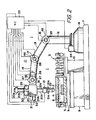
- FIGS. 1 and 2 there is shown a robotic positioning system 1 forming part of an electrical discharge machining (EDM) centre.
- the robotic system 1 is shown carrying a selected tool electrode 2 which it has transferred from a tool (electrode) storage magazine 3 (FIG. 2) for positioning it accurately with respect to a workpiece 4 in a work zone.
- the work zone is defined in a worktank 5 supplied with a dielectric liquid 6 and mounted on a base 7.
- the worktank 5 is normally carried by a cross-table 8 movably on a platform 9 which is securely mounted on the base 7.
- the tool storage magazine is shown as provided on a separate platform 10 mounted in a side- by-side relationship with the platform 9 on the base 8.
- the machining centre further includes an EDM power supply for electrically energizing the tool electrode 2 and the workpiece 4 and an automatic workpiece handing unit for automatically loading and unloading workpieces in the worktank 5.
- the robotic positioning system in the illustrated embodiment makes use of an articulated arm assembly 11 including successive arm members 12, 13, 14 and 15 pivotally interconnected at joints 16, 17 and 18.
- the distal arm member 15 carries a further or extremity arm section 20 which in turn carries a hand section 21 with mechanical fingers 21a grasping the electrode holder 2a.
- the extremity arm section 20 comprises a shaft 20a having the hand section 21 secured to its one end, the shaft being axially displaceable through a collar 20b which is, rotatably about its axis, mounted in a block 20c, which in turn is mounted on the arm member 15 pivotally about its axis 15a.
- the extremity arm section 20 is capable of tilt in a plane (vertical as shown) which is orthogonal to the axis 15a (horizontal as shown), in addition to having an ability to tilt in a vertical plane containing the axis 15a.
- the hand section 21 has an actuator 21b accommodated therein and operable by command signals furnished from a control unit 23 to actuate the mechanical fingers 20a to hold and release the tool electrode 2 as required.
- the first arm member 12 in the form of a vertical stand is, rotatably about its vertical axis, carried on the base section 19 and rotatable by a motor 24 mounted thereon.
- the second, third and fourth arm members 13, 14 and 15 are rotatable in a common plane about the joints 16, 17 and 18 with respect to the first, second and third arm members 12, 13 and 14 by means of motors or actuators 25, 26 and 27, respectively.
- the motors or actuators 24, 25, 26 and 27 are operable by respective command signals from the control unit 23.
- the fourth arm member 15 when rotated, tilts the further arm section 20 and hence the hand section 21 about the joint 18 in the vertical plane in which the arm members 13, 14 and 15 are rotated.
- a further motor 28 is carried on the arm member 15 to operate by a command signal from the control unit 23 to achieve a tilting of block 20c and hence the hand section 21 about the axis 15a.
- the collar 20b in the extremity arm section 20 carries a motor 29 operable by a command signal from the control unit 23 to axially displace the shaft 20a.
- the block 20c carries a motor 30 operable by a command signal from the control unit 23 to rotate the collar 20b about its axis with respect to the block 20c.
- the hand section 21 and hence the tool electrode 2 can, in principle, take any desired spacial position with their inclination and angular position with respect to a surface (e.g. upper) of the workpiece 4.
- the fourth arm member 15 may be positioned to extend horizontally with its axis 15a spaced from the workpiece surface by a prescribed distance and a centre of the block 20c located vertically above a reference point on the workpiece surface. The block 20c may then be positioned to locate the axis of the shaft 20a to lie in alignment with the vertical line on that reference point.
- the collar 20a may be rotationally positioned to make the shaped surface of the electrode 2 assume a prescribed angular position about that vertical line. Then, the shaft 20a may be axially moved to establish an initial vertical position of the tool electrode 2 for electroerosively machining the workpiece 4.
- the motor 29 is driven to controlledly advance the shaft 20a so that the tool electrode 2 moves downwards following erosive stock removal from the workpiece 4 while maintaining a small gap spacing therewith until a prescribed depth of machining is achieved in the workpiece 4.
- the robotic positioning system 1 further includes a gyroscope assembly 31 which provides a directional reference for monitoring the accuracy of a spacial orientation assumed by any one arm member, hand member or tool electrode upon achieving a predetermined movement.
- the gyro assembly 31 is shown as mounted on the shaft 20a in FIG. 1 and on the block 20c in FIG. 2.
- the assembly 1 has a conventional gyro structure comprising a rotor or wheel and axle which are diagrammatically. illustrated in FIG. 3 and designated at 31a and 31b, and a frame 31c for accommodating it.
- the gyro structure 31a, 31b is supported on a support 31d fixed in relation to the frame 31c, and is, as well known, set in rapid rotation or spinning with its axis 31e in a desired direction.
- the frame 31 is securely positioned on a movable member (i.e. the shaft 20a in FIG. 1 and on the block 20c in FIG. 2) for joint movement therewith in the robotic system.
- a movable member i.e. the shaft 20a in FIG. 1 and on the block 20c in FIG. 2
- the gyro frame 31c rotationally moves as a result of the rotational movements of arm members 12, 13, 14, 15 and the block 20c in FIG. 2 and further of the collar 20b in FIG. 1. Since each unit rotational movement may entail an error, such errors may accumulate so that even a greater error may develop from a target spacial orientation of the shaft 20a and the tool electrode 2 as commanded by the drive signals from the control unit 23. Under these circumstances, the gyro assembly 31 provides a highly accurate and reliable directional reference.
- the axle 31b in the gyro assembly 31 can be set to be precisely vertical or parallel to that vertical line. It is desirable to monitor if the shaft 20a upon movement to reach a target position is really oriented to be truly vertical.
- a sensing unit 32 is associated with the gyro assembly 31 as mounted on the shaft 20b in FIG. 1 and the block 20c in FIG. 2 for sensing an orientation of the shaft 20b or the block 20c with respect to the reference vertical axis 31e established in the gyro assembly 31.
- the sensing unit 32 may make use of any conventional principle for optically electrically or magnetically sensing a deflection of an axial body.
- an optical sensing unit 32 may comprise a pair of light sources 33, 34 and a pair of double light sensors 35, 36, all fixed in position with respect to the frame 31a in the gyro assembly 31.
- These elements 33-36 are arranged for X and Y axes around the axle 31b in such a way that the shadow caused by the axle 31b uniformly covers sensor halves 35a, 35b; 36a, 36b when the orientation of the movable member (20a, 20c) on which the gyro assembly 31 is mounted is in alignment with the set direction 31e.
- differential signals which develop at terminals 37 and 38 are representative of respective deviations of orientation along the axes X and Y. These signals are applied to the control unit to modify the drive signals applied to the motors or actuators 24, 25, 27 and/or 28 so that the differential valves are reduced to nil.
- FIG. 1 the electrical machining system is also shown as provided with an electrode- positioning jig unit 40.
- This unit 40 includes a first positioning plate 41 having the workpiece 4 securely mounted thereon.
- a plurality of positioning pins 42 projects on the plate 41.
- a second positioning plate 43 is detachably mounted on the electrode holder 2a and has a plurality of holes 44 bored therein.
- the pins 42 and the holes 44 are arranged so that when the electrode surface of the tool electrode 2 is properly positioned with respect to the workpiece, the holes 44 are capable of accepting the pins 42.
- the articulated arm assembly 11 is also shown as provided with braking units 45, 46 and 47 at joints 16, 17 and 18.
- the control unit 23 Upon ascertaining that all of the movable members in the robotic system have been moved as required to locate the tool electrode 2 at a predetermined positioning prior to initiation of an EDM operation, the control unit 23 provides a signal which actuates the braking units 45, 46 and 47 thereby to lock the arm members 13, 14 and 15 against any movement.
Landscapes
- Engineering & Computer Science (AREA)
- Robotics (AREA)
- Mechanical Engineering (AREA)
- Human Computer Interaction (AREA)
- Automation & Control Theory (AREA)
- Physics & Mathematics (AREA)
- Artificial Intelligence (AREA)
- Evolutionary Computation (AREA)
- Fuzzy Systems (AREA)
- Mathematical Physics (AREA)
- Software Systems (AREA)
- Manipulator (AREA)
Applications Claiming Priority (6)
| Application Number | Priority Date | Filing Date | Title |
|---|---|---|---|
| JP100953/83 | 1983-06-08 | ||
| JP10095383A JPS59227377A (ja) | 1983-06-08 | 1983-06-08 | ロボツト装置 |
| JP10772983A JPS59232732A (ja) | 1983-06-17 | 1983-06-17 | 電気加工装置 |
| JP107729/83 | 1983-06-17 | ||
| JP15789683A JPS6052233A (ja) | 1983-08-31 | 1983-08-31 | 電気加工用マシニングセンタ |
| JP157896/83 | 1983-08-31 |
Publications (2)
| Publication Number | Publication Date |
|---|---|
| EP0128763A2 true EP0128763A2 (de) | 1984-12-19 |
| EP0128763A3 EP0128763A3 (de) | 1986-09-10 |
Family
ID=27309351
Family Applications (1)
| Application Number | Title | Priority Date | Filing Date |
|---|---|---|---|
| EP84303906A Ceased EP0128763A3 (de) | 1983-06-08 | 1984-06-08 | Positionierungssystem für Roboter |
Country Status (2)
| Country | Link |
|---|---|
| US (1) | US4562391A (de) |
| EP (1) | EP0128763A3 (de) |
Cited By (4)
| Publication number | Priority date | Publication date | Assignee | Title |
|---|---|---|---|---|
| EP0206930A1 (de) * | 1985-06-21 | 1986-12-30 | Commissariat A L'energie Atomique | Raupenfahrzeug mit veränderbarer Geometrie |
| EP0504590A1 (de) * | 1991-03-19 | 1992-09-23 | BODENSEEWERK GERÄTETECHNIK GmbH | Verfahren zum Kalibrieren von hochgenauen Robotern |
| EP2412468A3 (de) * | 2010-07-29 | 2012-06-13 | Leistritz Turbomaschinen Technik GmbH | Verfahren zur Herstellung eines Metallbauteils |
| CN109811821A (zh) * | 2017-11-20 | 2019-05-28 | 迪尔公司 | 液压锤 |
Families Citing this family (25)
| Publication number | Priority date | Publication date | Assignee | Title |
|---|---|---|---|---|
| GB2164752B (en) * | 1984-09-22 | 1987-12-16 | Wiederaufarbeitung Von Kernbre | Monitoring remotely operable remote handling apparatus |
| EP0177901B1 (de) * | 1984-10-11 | 1989-04-05 | Kabushiki Kaisha Toshiba | Vorrichtung zum Ermitteln von Winkeln eines Roboterteiles |
| US4813125A (en) * | 1987-06-08 | 1989-03-21 | Utica Enterprises, Inc. | Method and apparatus for establishing the position of a datum reference from an object having dimensional variations within a tolerance range |
| US4782274A (en) * | 1987-07-23 | 1988-11-01 | Westinghouse Electric Corp. | End effector for robotic system |
| US4831549A (en) * | 1987-07-28 | 1989-05-16 | Brigham Young University | Device and method for correction of robot inaccuracy |
| US4887016A (en) * | 1987-09-21 | 1989-12-12 | Viking Systems International, Inc. | Portable robot with automatic set-up |
| US4949026A (en) * | 1987-12-07 | 1990-08-14 | Mead John A | Robot arm space stabilizer |
| US4919586A (en) * | 1988-05-25 | 1990-04-24 | Grasp, Inc. | Mechanical closed loop robotic arm end effector positioning system |
| JPH0366589A (ja) * | 1989-05-31 | 1991-03-22 | An Ey-Rang | ロボットの駆動制御回路 |
| JP2849939B2 (ja) * | 1990-05-07 | 1999-01-27 | 本田技研工業株式会社 | Sohc型内燃機関 |
| US5083070A (en) * | 1990-05-10 | 1992-01-21 | Accubilt, Inc. | Index table with center mounted robot arm |
| DE4306492C1 (de) * | 1993-03-03 | 1994-07-21 | Wolfram Dr Ing Rennau | Schweißzangenregelung |
| US5594434A (en) * | 1994-10-04 | 1997-01-14 | Rockwell International Corporation | Angular sensing system |
| US5655412A (en) * | 1994-10-24 | 1997-08-12 | Luik; Ilmar | Machine tool free of jerks and vibrations caused by the newtonian reaction forces |
| DE19525701A1 (de) * | 1995-07-14 | 1997-01-16 | Bayerische Motoren Werke Ag | Verfahren zur Bearbeitung eines Werkstückes |
| US6310312B1 (en) * | 1999-07-02 | 2001-10-30 | United Technologies Corporation | Method and apparatus for testing electrodes in an EDM process |
| JP2003187434A (ja) * | 2001-12-20 | 2003-07-04 | Fuji Photo Film Co Ltd | フレキシブル媒体への磁気転写方法 |
| EP1877693A4 (de) * | 2004-12-13 | 2010-05-26 | Optical Alchemy Inc | Mehrachsige kardanische aufhängung mit ineinandergeschachtelten schalen |
| FR2879949B1 (fr) * | 2004-12-24 | 2008-08-01 | Framatome Anp Sas | Procede et dispositif d'usinage a distance par electroerosion d'une zone d'une paroi metallique d'une piece |
| US8069004B2 (en) * | 2005-05-24 | 2011-11-29 | Nxp B.V. | System comprising a generating device and a comparing device |
| US9731392B2 (en) * | 2014-08-05 | 2017-08-15 | Ati Industrial Automation, Inc. | Robotic tool changer alignment modules |
| DE102014218169B4 (de) | 2014-09-11 | 2022-01-20 | MTU Aero Engines AG | Elektrochemische Bearbeitung eines Werkstücks |
| JP5975129B1 (ja) | 2015-03-02 | 2016-08-23 | 株式会社安川電機 | ロボット |
| JP6812095B2 (ja) * | 2015-10-22 | 2021-01-13 | キヤノン株式会社 | 制御方法、プログラム、記録媒体、ロボット装置、及び物品の製造方法 |
| CN110788873A (zh) * | 2018-08-03 | 2020-02-14 | 台达电子工业股份有限公司 | 机械手臂的自动对位系统及方法 |
Family Cites Families (12)
| Publication number | Priority date | Publication date | Assignee | Title |
|---|---|---|---|---|
| US3212651A (en) * | 1962-06-12 | 1965-10-19 | American Mach & Foundry | Manipulator |
| JPS5350224Y2 (de) * | 1973-09-25 | 1978-12-01 | ||
| US4156835A (en) * | 1974-05-29 | 1979-05-29 | Massachusetts Institute Of Technology | Servo-controlled mobility device |
| US4052654A (en) * | 1975-09-22 | 1977-10-04 | The Charles Stark Draper Laboratory, Inc. | Gyro stabilized inertial reference system with gimbal lock prevention means |
| FR2357942A1 (fr) * | 1976-07-09 | 1978-02-03 | Renault | Procede d'apprentissage pour robot et appareil en faisant application |
| GB1587787A (en) * | 1977-04-18 | 1981-04-08 | Inoue Japax Res | Electroerosion machining apparatus and methods |
| DE2851063A1 (de) * | 1978-11-25 | 1980-06-04 | Cloos Gmbh Carl | Vorrichtung zur automatischen fuehrung einer schweisspistole laengs einer vorprogrammierten schweissnaht |
| US4221997A (en) * | 1978-12-18 | 1980-09-09 | Western Electric Company, Incorporated | Articulated robot arm and method of moving same |
| US4412293A (en) * | 1981-03-30 | 1983-10-25 | Kelley Robert B | Robot system which acquires cylindrical workpieces from bins |
| US4403281A (en) * | 1981-04-03 | 1983-09-06 | Cincinnati Milacron Industries, Inc. | Apparatus for dynamically controlling the tool centerpoint of a robot arm off a predetermined path |
| US4409736A (en) * | 1981-07-31 | 1983-10-18 | The Charles Stark Draper Laboratory, Inc. | Null seeking system for remote center compliance device |
| JPS58125110A (ja) * | 1982-01-21 | 1983-07-26 | Fanuc Ltd | ロボツト制御方式 |
-
1984
- 1984-06-07 US US06/618,191 patent/US4562391A/en not_active Expired - Fee Related
- 1984-06-08 EP EP84303906A patent/EP0128763A3/de not_active Ceased
Cited By (6)
| Publication number | Priority date | Publication date | Assignee | Title |
|---|---|---|---|---|
| EP0206930A1 (de) * | 1985-06-21 | 1986-12-30 | Commissariat A L'energie Atomique | Raupenfahrzeug mit veränderbarer Geometrie |
| EP0504590A1 (de) * | 1991-03-19 | 1992-09-23 | BODENSEEWERK GERÄTETECHNIK GmbH | Verfahren zum Kalibrieren von hochgenauen Robotern |
| DE4108939A1 (de) * | 1991-03-19 | 1992-09-24 | Bodenseewerk Geraetetech | Verfahren zum kalibrieren von hochgenauen robotern |
| EP2412468A3 (de) * | 2010-07-29 | 2012-06-13 | Leistritz Turbomaschinen Technik GmbH | Verfahren zur Herstellung eines Metallbauteils |
| CN109811821A (zh) * | 2017-11-20 | 2019-05-28 | 迪尔公司 | 液压锤 |
| US11446805B2 (en) | 2017-11-20 | 2022-09-20 | Deere & Company | Hydraulic hammer |
Also Published As
| Publication number | Publication date |
|---|---|
| US4562391A (en) | 1985-12-31 |
| EP0128763A3 (de) | 1986-09-10 |
Similar Documents
| Publication | Publication Date | Title |
|---|---|---|
| US4562391A (en) | Robotic positioning system | |
| US4523100A (en) | Optical vernier positioning for robot arm | |
| US4919586A (en) | Mechanical closed loop robotic arm end effector positioning system | |
| KR960000294B1 (ko) | 용접 로보트 | |
| KR100200334B1 (ko) | 부품조립장치 | |
| US10391559B2 (en) | Machine tool | |
| US4617504A (en) | Positioning device | |
| SE464855B (sv) | Foerfarande vid en industrirobot foer kalibrering av en sensor | |
| WO2000078494A1 (fr) | Procede de soudage | |
| KR102016907B1 (ko) | 와이어 방전 시스템 및 상대 위치 산출 방법 | |
| US5035554A (en) | Method for determining the radius described by a tool | |
| EP0149682A1 (de) | Verfahren zur bestimmung der referenzortung eines industriellen roboters | |
| KR100441306B1 (ko) | 생산위치결정시스템 | |
| EP0194314A1 (de) | Regelsystem für die ortung eines werkzeugs | |
| US5570609A (en) | Industrial robot provided with means for setting reference positions for respective axes | |
| EP1177846B1 (de) | Werkzeugpositioniermethode, werkzeugpositioniervorrichtung und mechanische zuführeinrichtung zum positionieren eines werkzeuges | |
| CN110248759A (zh) | 电弧点调节杆安装结构、多关节焊接机器人以及焊接装置 | |
| US4816729A (en) | Closed loop machining system calibration | |
| CN114303109B (zh) | 数控机床的操作方法以及用于实施这样的方法的检测装置 | |
| JPH0463663A (ja) | 放電加工用電極の位置決め装置 | |
| JPH06142967A (ja) | レーザロボットのレーザヘッド補正方法 | |
| JPS6258850B2 (de) | ||
| JPH03193295A (ja) | 自動加工装置 | |
| JP2021019172A (ja) | ロボットハンド、ロボット、及び固定装置 | |
| GB2154163A (en) | Cylindrical grinding machine having position detection probe |
Legal Events
| Date | Code | Title | Description |
|---|---|---|---|
| PUAI | Public reference made under article 153(3) epc to a published international application that has entered the european phase |
Free format text: ORIGINAL CODE: 0009012 |
|
| AK | Designated contracting states |
Designated state(s): DE FR GB IT |
|
| PUAL | Search report despatched |
Free format text: ORIGINAL CODE: 0009013 |
|
| AK | Designated contracting states |
Kind code of ref document: A3 Designated state(s): DE FR GB IT |
|
| 17P | Request for examination filed |
Effective date: 19861024 |
|
| 17Q | First examination report despatched |
Effective date: 19880720 |
|
| STAA | Information on the status of an ep patent application or granted ep patent |
Free format text: STATUS: THE APPLICATION HAS BEEN REFUSED |
|
| 18R | Application refused |
Effective date: 19891201 |
|
| RIN1 | Information on inventor provided before grant (corrected) |
Inventor name: INOUE, KIYOSHI |