EP0136639A1 - Pikiermaschine mit quer zueinander sich bewegendem Werkstückträger und Nähmaschinenkopf - Google Patents
Pikiermaschine mit quer zueinander sich bewegendem Werkstückträger und Nähmaschinenkopf Download PDFInfo
- Publication number
- EP0136639A1 EP0136639A1 EP84111346A EP84111346A EP0136639A1 EP 0136639 A1 EP0136639 A1 EP 0136639A1 EP 84111346 A EP84111346 A EP 84111346A EP 84111346 A EP84111346 A EP 84111346A EP 0136639 A1 EP0136639 A1 EP 0136639A1
- Authority
- EP
- European Patent Office
- Prior art keywords
- carriage
- cloth
- quilting machine
- sewing head
- machine according
- Prior art date
- Legal status (The legal status is an assumption and is not a legal conclusion. Google has not performed a legal analysis and makes no representation as to the accuracy of the status listed.)
- Granted
Links
- 239000004744 fabric Substances 0.000 title claims abstract description 40
- 238000009958 sewing Methods 0.000 title claims abstract description 33
- 238000005192 partition Methods 0.000 claims description 5
- 230000002441 reversible effect Effects 0.000 claims 1
- 230000004048 modification Effects 0.000 description 2
- 238000012986 modification Methods 0.000 description 2
- 230000002411 adverse Effects 0.000 description 1
- 238000006073 displacement reaction Methods 0.000 description 1
- 230000000694 effects Effects 0.000 description 1
- 230000035515 penetration Effects 0.000 description 1
- 239000000700 radioactive tracer Substances 0.000 description 1
- 238000005096 rolling process Methods 0.000 description 1
- 125000006850 spacer group Chemical group 0.000 description 1
Images


Classifications
-
- D—TEXTILES; PAPER
- D05—SEWING; EMBROIDERING; TUFTING
- D05B—SEWING
- D05B11/00—Machines for sewing quilts or mattresses
Definitions
- This invention relates to a quilting machine with relatively moving cloth holder carriage and sewing head in mutually orthogonal directions.
- One type such as disclosed in UK Patent No. 1,207,451, comprises a first carriage, on which a cloth to be quilted is held, arranged to run linearly on a second carriage. The latter carriage runs, also linearly, on an orthogonal plane to that of the first carriage.
- Both carriages are driven to move under a stationary sewing head along a path determined by a template or other costraint.
- Another type of a quilting machine such as disclosed in French Patent No. 1,550,051, operates in precisely the opposite way, i.e. with the sewing head moving along orthogonal axes over a stationary carriage holding a cloth to be quilted.
- a further quilting machine type comprises one or more sewing heads which are driven back-and-forth relatively to a cloth which is being fed continuously lengthwise thereunder.
- the first two of the types mentioned above can provide elaborate sewing.
- the carriage drive poses on account of the inertia masses involved, somewhat narrow limits on operation, and the unavoidable shaking encountered adversely affects the quilting operation accuracy.
- the quilting machine of the third type finds application for just repeatitive quilting of an inferior class.
- a further object of this invention is to provide a quilting machine which is highly flexible in operation, in connection with its ability to perform elaborate seam. lines.
- a quilting machine which is characterized in that it comprises a cloth holder carriage whereon a cloth to be quilted is stretched on a horizontal plane and which is movable along a rectilinear path, above said cloth there being arranged at least one sewing head guided in an orthogonal direction to the carriage travel direction, and a means being provided for driving said carriage and sewing head along respective runways to cause the seam line to follow a preset pattern.
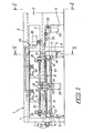
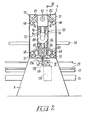
- an overhead frame comprising an upper horizontal beam 2 and lower horizontal beam 3 which are supported at the opposed ends thereof by two floor- standing pillars 4,5.
- the lower beam 3 is supported by a third pillar 6 located intermediately between the pillars 4,5-but shifted toward the latter.
- the beams 2,3 have, when viewed in cross-section, the shape of two U's opening toward each other.
- brackets 10,11 which protrude from said pillars in horizontal alignment and to which two respective horizontal longitudinal stringers 12,13 are attached which extend parallel to each other and perpendicularly to the frame 1.
- the longitudinal stringers 12,13 extend through the opening 8 to overhang on opposed sides of the frame 1.
- the ends of the longitudinal stringers 12,13 stand on the floor through substantially vertical adjustable height feet, 14 thereby enabling said longitudinal stringers to be supported on a truly horizontal plane.
- the longitudinal stringers have spacers 15 attached thereto to which are in turn attached two cylindrical bars 16,17 which serve as runways for a carriage 18 whereon a cloth to be quilted should be stretched.
- the carriage 18 comprises a rectangular frame formed by lengthwise 19 and crosswise 20 sectional members, having at its corners four idle wheels 21 which are grooved circumferentially and enable the carriage 18 to travel along the bars 16,17.
- the crossmembers 20 have the horizontal portions of two pairs of right-angled elements 22,23 attached thereto.
- the shaft 26 is driven rotatively via a center reduction gear 28 which receives its motion from a motor 29 through a drive belt 30 and respective pulleys 28a,29a keyed on the output shafts of the reduction gear and motor.
- the motor 29 and reduction gear 28 are mounted on a box-like bracket 31 attached to the crossmember 20.
- the links of the chains 34,35 comprise juxtaposed arms 40,41 (see Figure 5) which project in opposed directions and carry blocks 42,43 bristling with outwardly facing needles 44,45.
- blocks 42,43 Keyed on the shaft 26, adjacently to, and rotating concurrently with, the blocks 42,43, are disks 46,47 the outer diameter whereof is larger than that defined by the ends of the needles.
- the needles have the purpose of holding the cloth to be quilted along two longitudinal edges. Penetration of the needles into the cloth is achieved by means of a pair of circular brushes 48 carried rotatably in arms 49 articulated to the ends of extensions 50 of the pair of right-angled elements 23.
- the brushes 48 are coplanar with the needles 44, 45 and held against the latter by pneumatic jacks 51 interposed between the tops of said pair of right-angled elements 23 and oscillating arms 49.
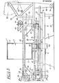
- the cloth which should be stretched between the needles 44,45 is picked up by a roll 52 supported on a frame 5 3 which is attached to the carriage 18 through a hinge 54.
- the frame 53 has two feet 55 comprising rotatable wheels 56 which run on a pair of rails 57 secured on the surface and parallel with the rails 16,17.
- the motion of the carriage 18 is derived from a gear motor 58 suspended, through brackets 59, from the lower beam 3 of the frame 1.
- the gear motor 58 drives a shaft 60 which is supported, at its opposed ends, on shoulders 61,62 projecting downwards from the beam 3.
- pinion gears 63,64 Keyed to the ends of the shaft 60 projecting beyond the shoulders 61,62 are pinion gears 63,64.
- the pairs of gear wheels 65,66 keep trained at a certain angle around the pinion gears 63,64 two chains 67 stretched between the front and rear crossmembers 20 of the carriage 18 to form two racks which are in mesh engagement with said pinion gears 63,64.
- the chains 34,35 are passed through the opening 7 as the carriage frame moves through the opening 8, thereby the beam 3 is located under the chains 34,35 and over the longitudinal stringers 19.
- the bars 68,69 have a square cross-section and are positioned edgewise on the sidewalls of the beams 2,3 by means of diagonal elements 71,72 whereto they are attached.
- the carriage 70 comprises two planeparallel plates 73,74 identical to each other and shaped like a "C" with two horizontal portions 75,76 which extend into the beams 2,3 and are connected through vertical portions 77 (see Figure 4).
- the plates 73,74 are interconnected by partitions interposed between the upper portions 75 and partitions 79 interposed between the lower portions 76.
- Attached to the outer faces of the plates 73,74 are pairs of small blocks 81,82,83 and 84, of which the first pair are rigid with the upper portions 75 and the second pair with the lower portions 76.
- Cantilevered from each block 81-84 are a pair of small rollers 85 having their rotation axes arranged at 90° to each other and in tangential rolling engagement with the juxtaposed faces of the bars 68,69.
- Mounted between the vertical portions 77 of the carriage 70 is a bracket 86 which projects from the vertical portions 77 in the opposite direction to the horizontal portions 76.
- the pulley 91 is keyed to a shaft 92 which is journaled within, and carried rotatably in between two partitions 78 and extending on the centerplane of the carriage between the upper portions 75 over nearly the full length of the latter.
- a positive drive sprocket wheel 93 Keyed to the shaft 92, beside the pulley 91, is a positive drive sprocket wheel 93 which, through a toothed belt 94, transmits the motion to a second sprocket wheel 95 rotatively keyed to a shaft 96 journalled at the partitions 79.
- the shaft 96 is parallel to the upper shaft 92 and extends between the horizontal lower portions 76, of the carriage 70.
- a plate 97 Fastened between the upper portions 75 is a plate 97 having slots 98 extending parallel to the shaft 92.
- a sewing head 101 of conventional design Suspended from the plate 97, by means of brackets 99, 100 is a sewing head 101 of conventional design, which receives its motion from the shaft 92 through a drive including two sprocket wheels 102,103 and a corresponding toothed belt 104.
- the pulley 102 is rotatively rigid with a splined portion 105 of the shaft 92 and has a circumferentially grooved side bushing 106, with which there engages a yoke 107 presented at the top of the bracket 100.
- each of the sewing heads 101,111 Cooperating with each of the sewing heads 101,111 are respective "hook" devices 115,116 mounted on respective plates 117,118 interposed between the ' carriage lower portions 76.
- the hook device 115 can be shifted across the plate 117 to proceed the displacement of the sewing head, whereas the device 116 is stationary.
- the device 115 receives its motion from the shaft 96 via a belt drive 119 which is trained around a pulley 120 keyed to the shaft 96 and a pulley 121 keyed to a shaft suitably journaled within the hook device 115.
- the device 116 is juxtaposed to the device 115, in order to extend the lateral bounds of the sewing machine working range and improve access to the cops thereby facilitating their replacement.
- a reversing gear which comprises two gear wheels 122,123 accommodated in the device and meshing together, of which the wheel 122 drives the hook and the other wheel 123 is secured on the axle carrying the pulley 124 which receives its motion from the shaft 96 through the belt 125 and pulley 126.
- the shaft 96 is divided into two sections which may be coupled together by means of an axially sliding splined bushing 127.
- the bushing 127 is in constant rotary engagement with the end of one section and can overlap the end of the adjacent section to rotatively engage the latter on operation of a yoke lever 128 journalled between the portions 76.
- the movement of the carriage 70 along the guides 68, 69 is generated by a gear motor 130 having a sprocket wheel 131 around which a chain 132 is trained.
- the lower run of the chain 132 extends below the beam 3 through openings in the pillars 4 and 6 and is passed around a sprocket wheel 133 journalled axially in a support 134 attached to the outside of the pillar 4.
- the upper run of the chain 132 extends into the beam 3 and is deflected away from the axis of said sprocket wheel 131 by an idle roller 135, thereby defining a horizontal tra jeo- tory, parallel to said lower run.
- One point on the chain upper run is secured to the carriage 70 by means of a small plate 136 ( Figure 2).
- the quilting machine described hereinabove operates as follows. First, the cloth is positioned on the carriage 18. To accomplish this, the cloth is unwound from the roll 52 and deflected horizontally by a roller 137 on the frame 53 ( Figure 3) under the brushes 48 which drive its edges onto the needles 44, 45. The driving of the chains 34,35 generated by means of the motor 29 causes the desired length of cloth to be fed a corresponding distance under the sewing heads and over the respective hook devices.
- the sewing step begins with the actuation of the motor 88 which powers the sewing heads 101,111 and hook devices 115,116.
- the motors 58 and 130 are operated to move the cloth holding carriage 18 along the rails 16, 17, and respectively, the carriage 70 along the bars 68,69.
- the orthogonal reciprocating movements of the carriages 18 and 70 enable the effectuation of any seam lines and, hence, of an indefinite range of patterns.
- the carriage drive motors are suitably controlled by a microprocessor or the like electronic processor. It is possible, however, to perform the quilting operations by controlling the carriages through a tracer point arranged to follow a template.
- a fresh cloth section paid out from the roll 52 can be stretched between the chains 34,35,whilst the completed quilted cloth section is simultaneously ejected from the carriage 18.
- Disengagement of the needles 44,45 is accomplished by the disks 46,47 which, having a larger diameter, than that defined by the ends of said needles, will raise the cloth edges off the needles as the cloth is on the point of leaving the carriage.
- the machine may be equipped with a cutter device to sever the completed quilted cloth section from the remaining cloth.
- the invention fully achieves its objects.
- the cloth to be quilted is only allowed to move in one direction, thus greatly reducing the margin for errors due to the carriage being stopped and restarted.
- the invention as disclosed is susceptible to many modifications and changes.
- One of these envisages, for instance, that a frame be used instead of the chains 34,35 whereon the cloth would be stretched and held down by suitable clamps.
- Another modification provides for the roll of cloth to be either supported directly, on the carriage or held stationary on the floor.
- the quantity of rolls may vary according to the number of layers composed within the manufactured article.
Landscapes
- Engineering & Computer Science (AREA)
- Textile Engineering (AREA)
- Sewing Machines And Sewing (AREA)
Applications Claiming Priority (2)
| Application Number | Priority Date | Filing Date | Title |
|---|---|---|---|
| IT357483 | 1983-09-30 | ||
| IT03574/83A IT1195422B (it) | 1983-09-30 | 1983-09-30 | Macchina trapuntatrice con carrello portapanni e testa cucitrice mobili fra di loro in direzioni ortogonali |
Publications (2)
| Publication Number | Publication Date |
|---|---|
| EP0136639A1 true EP0136639A1 (de) | 1985-04-10 |
| EP0136639B1 EP0136639B1 (de) | 1989-12-13 |
Family
ID=11109981
Family Applications (1)
| Application Number | Title | Priority Date | Filing Date |
|---|---|---|---|
| EP84111346A Expired EP0136639B1 (de) | 1983-09-30 | 1984-09-24 | Pikiermaschine mit quer zueinander sich bewegendem Werkstückträger und Nähmaschinenkopf |
Country Status (5)
| Country | Link |
|---|---|
| US (1) | US4669405A (de) |
| EP (1) | EP0136639B1 (de) |
| DE (1) | DE3480723D1 (de) |
| ES (1) | ES536746A0 (de) |
| IT (1) | IT1195422B (de) |
Cited By (7)
| Publication number | Priority date | Publication date | Assignee | Title |
|---|---|---|---|---|
| DE3513627A1 (de) * | 1985-04-16 | 1986-10-16 | Badenia GmbH Steppdeckenfabrik, 7632 Friesenheim | Verfahren zum kontinuierlichen steppen |
| GB2203760A (en) * | 1987-04-24 | 1988-10-26 | Brother Ind Ltd | Sewing machine |
| EP0275017A3 (de) * | 1987-01-09 | 1989-07-26 | RESTA COMMERCIALE S.r.l. | Absteppmaschine mit werkstücktragendem Zylinder mit einstellbarer Länge |
| EP0275016A3 (de) * | 1987-01-09 | 1989-08-02 | RESTA COMMERCIALE S.r.l. | Vorrichtung zum automatischen Führen eines abzusteppenden Werkstücks zu einem werkstücktragenden Zylinder einer Absteppmaschine |
| US5040473A (en) * | 1989-07-03 | 1991-08-20 | Aktiengesellschaft Adolph Saurer | Method of, and apparatus for, processing textile material webs, particularly for manufacturing quilts and the like |
| US8042478B2 (en) | 2007-09-10 | 2011-10-25 | Atlanta Attachment Co. | Automatic panel cutting and seaming system |
| ITMI20131892A1 (it) * | 2013-11-14 | 2015-05-15 | Alberto Landoni | Macchina trapuntatrice multiaghi e relativo metodo di trapuntatura |
Families Citing this family (18)
| Publication number | Priority date | Publication date | Assignee | Title |
|---|---|---|---|---|
| DE3819277C1 (de) * | 1988-06-07 | 1989-12-28 | Duerkoppwerke Gmbh, 4800 Bielefeld, De | |
| US4876976A (en) * | 1988-07-18 | 1989-10-31 | Td Quilting Machinery | Automatic quilting machine and method for specialized quilting of patterns which can be controlled by a remote joystick and monitored on a video screen including pattern duplication through a reprogrammable computer |
| US4860675A (en) * | 1988-07-18 | 1989-08-29 | Td Quilting Machinery | Automatic quilting machine for specialized quilting of patterns which can be controlled by a remote joy stick and monitored on a video screen |
| US4953485A (en) * | 1989-04-10 | 1990-09-04 | Td Quilting Machinery | Automatic quilting machine for specialized quilting of patterns which can be created by utilizing computer graphics in conjunction with a reprogrammable computer |
| IT1233775B (it) * | 1989-04-21 | 1992-04-17 | Resta Commerciale | Macchina trapuntatrice con telaio portapanno stazionario e teste cucitrici mobili in direzioni ortogonali |
| US4953483A (en) * | 1989-08-04 | 1990-09-04 | Td Quilting Machinery | Automatic quilting machine and method for specialized quilting of patterns with separate computers to control the stitching and table movement functions |
| IT1248781B (it) * | 1990-08-17 | 1995-01-28 | Resta Commerciale Srl Ora Rest | Apparecchiatura per effettuare la trapuntatura di panni in genere. |
| US5506487A (en) * | 1991-03-28 | 1996-04-09 | General Electric Company | Systems and methods for driving a compressor with a motor |
| US5423192A (en) * | 1993-08-18 | 1995-06-13 | General Electric Company | Electronically commutated motor for driving a compressor |
| US5287820A (en) * | 1991-05-02 | 1994-02-22 | Nahmaschinenfabrik Emil Stutznacker Gmbh & Co., Kg | Movable and relatively positionable sewing units for sewing stationary material |
| US5675231A (en) * | 1996-05-15 | 1997-10-07 | General Electric Company | Systems and methods for protecting a single phase motor from circulating currents |
| JP2000245985A (ja) * | 1999-02-26 | 2000-09-12 | Tokai Ind Sewing Mach Co Ltd | ミシンの動力伝達装置 |
| KR100419893B1 (ko) * | 2001-05-30 | 2004-03-04 | 썬스타 특수정밀 주식회사 | 다두식 자수기의 구동장치 |
| US6631688B1 (en) | 2002-04-24 | 2003-10-14 | John D. Maag | Quilting rack for sewing machines |
| JP2004049481A (ja) * | 2002-07-18 | 2004-02-19 | Tokai Ind Sewing Mach Co Ltd | 多頭ミシン |
| JP2006340737A (ja) * | 2003-08-05 | 2006-12-21 | Tokai Ind Sewing Mach Co Ltd | ミシンフレーム |
| US6932007B1 (en) | 2003-08-30 | 2005-08-23 | Kevin Beauchamp | Variable pattern making jig for a quilting machine |
| US11180878B1 (en) | 2021-01-08 | 2021-11-23 | Mark S. Meier | Quilting machine with tilting sewing assembly |
Citations (3)
| Publication number | Priority date | Publication date | Assignee | Title |
|---|---|---|---|---|
| US1946868A (en) * | 1930-10-20 | 1934-02-13 | Carlin Comforts Inc | Sewing mechanism for quilts and the like |
| DE1119092B (de) * | 1956-05-30 | 1961-12-07 | E Stutznaecker Fa | Vielnadelnaehmaschine zur Erzeugung von Zierstichen auf polsterartigem Naehgut |
| US3837305A (en) * | 1973-08-17 | 1974-09-24 | Cash Machine Co | Dual head border panel manufacturing machine |
Family Cites Families (12)
| Publication number | Priority date | Publication date | Assignee | Title |
|---|---|---|---|---|
| US3125047A (en) * | 1964-03-17 | Pattern controlled driving mechanism for quilting machine | ||
| US2059845A (en) * | 1934-05-16 | 1936-11-03 | Joseph W Bowersox | Machine for quilting mattress borders |
| US3046921A (en) * | 1960-01-05 | 1962-07-31 | Schwarzberger Arthur | Follower units for quilting machines |
| DE1485519A1 (de) * | 1961-10-14 | 1969-06-19 | Zangs Ag Maschf | Vorrichtung zum Umsetzen eines in einem Stickrahmen einer Stickmaschine bestickten Stoffeldes einer Stoffbahn |
| US3180293A (en) * | 1964-01-09 | 1965-04-27 | Cash Machine Co James | Quilting machine |
| FR1550051A (de) * | 1964-10-09 | 1968-12-20 | ||
| US3417645A (en) * | 1965-07-06 | 1968-12-24 | Richard A Burnette | Apparatus for sensing and cutting along the edge of a thickened portion of a traveling web |
| US3354850A (en) * | 1965-08-25 | 1967-11-28 | Wayne G Story | Feed control mechanism for quilting machine arrangement |
| FR1544182A (fr) * | 1967-09-21 | 1968-10-31 | Roubane Ets | Machine à piquer ou broder à multiples aiguilles |
| GB1207451A (en) * | 1968-02-20 | 1970-10-07 | Improvements in or relating to guide tracks | |
| US4233916A (en) * | 1978-01-10 | 1980-11-18 | Emb-Tex Corporation | Process and apparatus for producing continuous embroidered fabrics |
| JPS6043145B2 (ja) * | 1982-02-23 | 1985-09-26 | プリンスミシン株式会社 | 布団等のミシン装置 |
-
1983
- 1983-09-30 IT IT03574/83A patent/IT1195422B/it active
-
1984
- 1984-09-24 US US06/653,794 patent/US4669405A/en not_active Expired - Lifetime
- 1984-09-24 DE DE8484111346T patent/DE3480723D1/de not_active Expired - Lifetime
- 1984-09-24 EP EP84111346A patent/EP0136639B1/de not_active Expired
- 1984-09-28 ES ES536746A patent/ES536746A0/es active Granted
Patent Citations (3)
| Publication number | Priority date | Publication date | Assignee | Title |
|---|---|---|---|---|
| US1946868A (en) * | 1930-10-20 | 1934-02-13 | Carlin Comforts Inc | Sewing mechanism for quilts and the like |
| DE1119092B (de) * | 1956-05-30 | 1961-12-07 | E Stutznaecker Fa | Vielnadelnaehmaschine zur Erzeugung von Zierstichen auf polsterartigem Naehgut |
| US3837305A (en) * | 1973-08-17 | 1974-09-24 | Cash Machine Co | Dual head border panel manufacturing machine |
Cited By (8)
| Publication number | Priority date | Publication date | Assignee | Title |
|---|---|---|---|---|
| DE3513627A1 (de) * | 1985-04-16 | 1986-10-16 | Badenia GmbH Steppdeckenfabrik, 7632 Friesenheim | Verfahren zum kontinuierlichen steppen |
| EP0275017A3 (de) * | 1987-01-09 | 1989-07-26 | RESTA COMMERCIALE S.r.l. | Absteppmaschine mit werkstücktragendem Zylinder mit einstellbarer Länge |
| EP0275016A3 (de) * | 1987-01-09 | 1989-08-02 | RESTA COMMERCIALE S.r.l. | Vorrichtung zum automatischen Führen eines abzusteppenden Werkstücks zu einem werkstücktragenden Zylinder einer Absteppmaschine |
| GB2203760A (en) * | 1987-04-24 | 1988-10-26 | Brother Ind Ltd | Sewing machine |
| GB2203760B (en) * | 1987-04-24 | 1991-05-01 | Brother Ind Ltd | Sewing machine |
| US5040473A (en) * | 1989-07-03 | 1991-08-20 | Aktiengesellschaft Adolph Saurer | Method of, and apparatus for, processing textile material webs, particularly for manufacturing quilts and the like |
| US8042478B2 (en) | 2007-09-10 | 2011-10-25 | Atlanta Attachment Co. | Automatic panel cutting and seaming system |
| ITMI20131892A1 (it) * | 2013-11-14 | 2015-05-15 | Alberto Landoni | Macchina trapuntatrice multiaghi e relativo metodo di trapuntatura |
Also Published As
| Publication number | Publication date |
|---|---|
| ES8600794A1 (es) | 1985-10-16 |
| DE3480723D1 (de) | 1990-01-18 |
| ES536746A0 (es) | 1985-10-16 |
| EP0136639B1 (de) | 1989-12-13 |
| IT1195422B (it) | 1988-10-19 |
| US4669405A (en) | 1987-06-02 |
| IT8303574A0 (it) | 1983-09-30 |
Similar Documents
| Publication | Publication Date | Title |
|---|---|---|
| EP0136639B1 (de) | Pikiermaschine mit quer zueinander sich bewegendem Werkstückträger und Nähmaschinenkopf | |
| US4777706A (en) | Apparatus for manufacturing endless needled paper machine felts | |
| US6945018B2 (en) | Wrapping machine and top foil wrapping machine | |
| US4463483A (en) | Fabric napping apparatus | |
| CN109837728B (zh) | 一种自动切割出预定形状片的装置 | |
| GB1420577A (en) | Automatic stacking machine for the stacking of layers of bars in particular rolled shapes | |
| US5491877A (en) | Apparatus for vertically displacing a shiftable bottom of a coiler can | |
| CN115125718B (zh) | 自动折衣机 | |
| US3354850A (en) | Feed control mechanism for quilting machine arrangement | |
| US5938400A (en) | Loading and unloading apparatus, in particular for loading and unloading presses | |
| US4477065A (en) | Belt feed apparatus for cloth spreading machine | |
| US6868765B2 (en) | Contour-cutting machine having a light-weight knife carrier | |
| US5325802A (en) | Sewing machine for large-surface, frame clamped material | |
| US3791177A (en) | Circular knitting machines | |
| DE2023186C3 (de) | ||
| US5079800A (en) | Bale supporting device for a fiber bale opener | |
| US6966743B2 (en) | Device for pushing a stack of printed products from a table | |
| CN206986483U (zh) | 人造草坪簇绒机机架 | |
| JPS606040Y2 (ja) | 延反機用原反供給装置 | |
| US4587813A (en) | Apparatus for applying treatment material to a textile material | |
| JPH0671720B2 (ja) | ウォータジェット加工機 | |
| JPH0780576A (ja) | 自動送り装置 | |
| GB1589565A (en) | Apparatus for cleaning fabrics | |
| CN219044748U (zh) | 一种用于布料处理装置的落布装置 | |
| CN223467990U (zh) | 一种码布机布料张紧装置 |
Legal Events
| Date | Code | Title | Description |
|---|---|---|---|
| PUAI | Public reference made under article 153(3) epc to a published international application that has entered the european phase |
Free format text: ORIGINAL CODE: 0009012 |
|
| AK | Designated contracting states |
Designated state(s): CH DE FR GB LI |
|
| 17P | Request for examination filed |
Effective date: 19851003 |
|
| 17Q | First examination report despatched |
Effective date: 19870915 |
|
| GRAA | (expected) grant |
Free format text: ORIGINAL CODE: 0009210 |
|
| AK | Designated contracting states |
Kind code of ref document: B1 Designated state(s): CH DE FR GB LI |
|
| ET | Fr: translation filed | ||
| REF | Corresponds to: |
Ref document number: 3480723 Country of ref document: DE Date of ref document: 19900118 |
|
| PLBE | No opposition filed within time limit |
Free format text: ORIGINAL CODE: 0009261 |
|
| STAA | Information on the status of an ep patent application or granted ep patent |
Free format text: STATUS: NO OPPOSITION FILED WITHIN TIME LIMIT |
|
| 26N | No opposition filed | ||
| REG | Reference to a national code |
Ref country code: GB Ref legal event code: IF02 |
|
| PGFP | Annual fee paid to national office [announced via postgrant information from national office to epo] |
Ref country code: FR Payment date: 20030828 Year of fee payment: 20 |
|
| PGFP | Annual fee paid to national office [announced via postgrant information from national office to epo] |
Ref country code: GB Payment date: 20030912 Year of fee payment: 20 |
|
| PGFP | Annual fee paid to national office [announced via postgrant information from national office to epo] |
Ref country code: DE Payment date: 20031017 Year of fee payment: 20 |
|
| PGFP | Annual fee paid to national office [announced via postgrant information from national office to epo] |
Ref country code: CH Payment date: 20031104 Year of fee payment: 20 |
|
| PG25 | Lapsed in a contracting state [announced via postgrant information from national office to epo] |
Ref country code: LI Free format text: LAPSE BECAUSE OF EXPIRATION OF PROTECTION Effective date: 20040923 Ref country code: GB Free format text: LAPSE BECAUSE OF EXPIRATION OF PROTECTION Effective date: 20040923 Ref country code: CH Free format text: LAPSE BECAUSE OF EXPIRATION OF PROTECTION Effective date: 20040923 |
|
| REG | Reference to a national code |
Ref country code: GB Ref legal event code: PE20 |
|
| REG | Reference to a national code |
Ref country code: CH Ref legal event code: PL |