EP0139018A1 - Assemblage de têtes transductrices magnétiques d'un seul type de pôles magnétiques pour enregistrement perpendiculaire - Google Patents
Assemblage de têtes transductrices magnétiques d'un seul type de pôles magnétiques pour enregistrement perpendiculaire Download PDFInfo
- Publication number
- EP0139018A1 EP0139018A1 EP84901220A EP84901220A EP0139018A1 EP 0139018 A1 EP0139018 A1 EP 0139018A1 EP 84901220 A EP84901220 A EP 84901220A EP 84901220 A EP84901220 A EP 84901220A EP 0139018 A1 EP0139018 A1 EP 0139018A1
- Authority
- EP
- European Patent Office
- Prior art keywords
- magnetic
- recording
- magnetic pole
- reproducing
- main magnetic
- Prior art date
- Legal status (The legal status is an assumption and is not a legal conclusion. Google has not performed a legal analysis and makes no representation as to the accuracy of the status listed.)
- Granted
Links
Images



Classifications
-
- G—PHYSICS
- G11—INFORMATION STORAGE
- G11B—INFORMATION STORAGE BASED ON RELATIVE MOVEMENT BETWEEN RECORD CARRIER AND TRANSDUCER
- G11B5/00—Recording by magnetisation or demagnetisation of a record carrier; Reproducing by magnetic means; Record carriers therefor
- G11B5/127—Structure or manufacture of heads, e.g. inductive
- G11B5/1278—Structure or manufacture of heads, e.g. inductive specially adapted for magnetisations perpendicular to the surface of the record carrier
Definitions
- the present invention relates to a complex magnetic transducer head of a single magnetic pole type for perpendicular mode recording suitable for use as a recording and reproducing head of a flexible disc apparatus in which, for example, a flexible disc is used as a magnetic recording medium.
- a flexible disc apparatus which uses a flexible magnetic disc as a magnetic recording medium.
- the flexible disc apparatus uses one magnetic transducer head to carry out both the recording and playback.
- Such flexible disc apparatus has a disadvantage of mis-tracking caused by a little displacement of a magnetic .recording medium upon installing (chucking), contraction and expansion of the magnetic recording medium due to the. change of temperature and humidity of the environment. Particularly when the re-recording is carried out, the previously recorded data can not be fully erased due to the mis-tracking and so on. There is then a disadvantage that upon reproducing, accurate data can not be obtained.
- a magnetic transducer . head for perpendicular recording mode previously proposed by the present applicant in the publicated document of the Japanese patent application unexamined No. 153216/1983 can be used, which is capable of carrying out the high density magnetic recording (short wavelength recording) and which can easily be produced as shown in Fig. 1.
- a magnetic transducer head H for perpendicular mode recording disclosed therein is formed such that a main magnetic pole 1 made of a thin film of soft magnetic material having a predetermined width to oppose at its one end a magnetic recording medium is sandwiched by guard blocks 2, 2' and integrated therewith.
- the guard blocks 2, 2' are respectively formed of non-magnetic guard members 3, 3' extended from the contact surface with the magnetic recording medium to a predetermined position and magnetic core members 4, 4' bonded to the lower surfaces thereof and extended to the rear sides thereof.
- magnetic core members 4, 4' there are formed auxiliary pole members 6, 6' bonded to the main magnetic pole 1 and wound therearound a coil 5 and grooves 8, 8' for magnetically separating the auxiliary pole members 6, 6' with return path portions 7, 7', each of which becomes a return path of a magnetic flux of the main magnetic pole 1.
- the coil 5 is wound around the main magnetic pole 1 through the auxiliary magnetic pole members 6, 6'. According to such magnetic transducer head for perpendicular mode recording, it is possible to carry out the high density magnetic recording.
- the present invention is to provide a magnetic transducer head for perpendicular mode recording in which even when the displacement of track is caused by the displacement of the magnetic recording medium upon mounting and the contraction and expansion of the magnetic recording medium due to the change of temperature and humidity, upon rewriting, it is possible to prevent the previously recorded data from not being erased completely, thus the accurate data being obtained upon reproducing.
- a complex magnetic transducer head of single magnetic pole type for perpendicular mode recording comprises a perpendicular mode magnetic recording and reproducing head portion which includes a recording and reproducing main magnetic pole having a predetermined width made of a thin film of soft magnetic material and confronting at its one end a magnetic recording medium, a non-magnetic guard member for sandwiching the recording and reproducing main magnetic pole at its both sides on a contact surface with the magnetic recording medium, a magnetic core portion integrated with the non-magnetic material guard member, contacting with at least one surface of the recording and reproducing main magnetic pole and disposed at the position remote backward from the magnetic recording medium by a predetermined distance and grooves formed in the magnetic core portion for separating a first auxiliary magnetic pole portion contacting with the recording and reproducing main magnetic pole and a return path portion which becomes a return path of magnetic flux from the recording and reproducing main magnetic pole, this perpendicular mode magnetic recording and reproducing head portion having a coil wound around the recording and reproducing main magnetic pole
- reference numeral 10 designates a main magnetic pole for recording and reproducing made of a thin film of soft magnetic material and in which its one end in contact with a magnetic recording medium 11 is made to have a predetermined width.
- the main magnetic pole 10 for recording and reproducing is integrally sandwiched at its both sides by non-magnetic guard members 12a and 12b having a predetermined thickness, and a magnetic core 13a and a non-magnetic member 13b are bonded to the lower surfaces of the non-magnetic guard members 12a and 12b so as to integrally sandwich the main magnetic pole 10 for recording and reproducing at its both sides.
- the magnetic core 13a formed behind the non-magnetic guard member 12a constructs a return path of a magnetic flux generated from the main magnetic pole for recording and reproducing 10.
- a groove 15 On the side of the magnetic core 13a contacting with the non-magnetic member 12a and in the vicinity of the main magnetic pole 10 for recoding and reproducing, there is formed a groove 15 which separates an auxiliary magnetic pole member 14a disposed near the main magnetic pole 10 for recording and reproducing from a return path member 14b which becomes a return path of the magnetic flux generated from the main magnetic pole 10 for recording and reproducing.
- a predetermined groove 16 is formed on the non-magnetic member 13b at its side contacting with the non-magnetic guard member 12b.
- the magnetic recording medium 11 used here is formed such that on a substrate lla made of, for example, synthetic resin is formed a high magnetic permeability material layer llb on which a perpendicular magnetic recording layer llc is further formed.
- the magnetic cores 13a and 13c may be formed of non-magnetic material at their sides remote from the magnetic recording medium.
- Reference numerals 18a and 18b respectively designate main magnetic poles for tunnel erase made of a thin film of soft magnetic material and which are disposed at the down stream from the main magnetic pole 10 for recording and reproducing.
- the main magnetic poles 18a and 18b for erasing, working for so-called tunnel erase are disposed to have a spacing smaller than the width of the main magnetic pole 10 for recording and reproducing.
- the main magnetic poles 18a and 18b for tunnel erase are respectively formed on a surface opposite to the surface with the spacing along a width direction of the recording and reproducing main magnetic pole smaller than the width of the main magnetic pole 10 for recording and playback in which the main magnetic pole 10 for recording and playback is bonded to the non-magnetic guard member 12b and the non-magnetic member 13b. Then, the main magnetic poles 18a, 18b for erasing are sandwiched at their both sides by the non-magnetic guard member 12b, the non-magnetic member 13b and the non-magnetic guard member 12c, the magnetic core 13c bonded to its rear surface.
- the magnetic core 13c constructs the return path of the magnetic fluxes generated from the main magnetic poles 18a, 18b for tunnel erase.
- a groove 20 which separates an auxiliary magnetic pole member 19a formed near the main magnetic poles 18a, 18b for tur.nel erase from a return path member 19a of the magnetic flux generated from the main magnetic poles 18a, 18b for turnel erase.
- a coil 21 for erasing is wound around the main magnetic poles 18a, 18b for tunnel erase.
- Fig. 4A A manufacturing method for producing the complex magnetic transducer head of single magnetic pole type for perpendicular mode recording will hereinafter be described with reference to Fig. 4 and the followings.
- the non-magnetic block members 22 and 23 are made of material which is desired to be dense, with a'thermal expansion coefficient similar to ferrite and hard (for example, non-magnetic ferrite such as Zn- ferrite and the like, forsterite, photo ceram, crystallized glass, barium titanate, calcium titanate, Al 2 O 3 -TiC series or ZrO 2 -series ceramic and so on).
- non-magnetic block member 22 On one non-magnetic block member 22 are formed grooves 24 which will become the winding apertures 16 with a spacing of a predetermined dimension (Fig. 4B).
- the surface on which the grooves are formed is mirror-polished, while the other non-magnetic block member 23 is mirror-polished.
- the two non-magnetic block members are bonded together by melt bonding by glass, organic adhesive agent such as epoxy resin and so on, inorganic adhesive agent such as water-glass and so on (Fig. 4C).
- the non-magnetic block members are cut out at the intermediate portion of the grooves 24 and in parallel to the groove 24 and the cut-out surface is mirror-polished.
- the thicknesses (Wl and W2) of the cores at the winding aperture 16 give the diameter of the windings, they are important.
- the diameter of the winding is made as small as possible, thus the thickness of the core being preferably made as thin as possible. Therefore, as far as the mechnical strength permits or as far as the work technique permits, it is desired that the thickness of the core is made as thin as possible. It is desirable that such thickness is selected to be less than, for example, 100 ⁇ m or 50 ⁇ m, if possible. It is desired to reduce the thickness of particularly the recording and reproducing winding side which requires the sensitivity severely.
- the tunnel erase side is not required to have so high sensitivity as the recording and reproducing side is, in order to keep the strength as a whole, it may be considered that the thickness of the recording and reproducing side is reduced, while that of the tunnel erase side is increased more than the thickness of the recording and reproducing side.
- the mirror-polished surface and the side surface are formed to have a right angle with high precision and a broken-off of the edge portion is reduced so as to form a correct edge portion. If the front surface as, for example, shown in Fig. 4B is mirror-polished in advance and then the grooves are formed at a right angle with high accuracy, such condition can be realized relatively easily.
- the recording and reproducing main magnetic pole 10 and the main magnetic poles 18a, 18b for tunnel erase are formed on the mirror-polished surface.
- a layer made of Si0 2 , Si 3 N 4 , Al 2 O 3 , Zro 2 and the like is deposited on both mirror-polished surfaces by sputtering, vacuum evaporation, ion plating and so on to have a thickness of about 0.1 to 1.0 pm. It is desired that the layer is formed under the condition capable of forming a layer as dense as possible. It is possible to omit the above layer but this layer can improve the magnetic characteristic of a magnetic thin film which is deposited on the above layer.
- a magnetic thin film (a magnetic film having a high magnetic permeability such as permalloy, sendust alloy, an amorphous magnetic film, for example, Co-Zr, Co-Zr-Nb and so on) so as to have a thickness of about 0.05 pm to 3 pm by sputtering, vacuum evaporation, ion plating, plating and so on. This thickness is determined in consideration of resolution, recording and reproducing sensitivity and so on, and the thickness ranging from about 0.1 ⁇ m to 0.5 pm is practical.
- this magnetic film is subjected to etching process (wet or dry system) using a photolithography technique so as to make a stripe pattern of a predetermined track width and a spacing.
- etching process wet or dry system
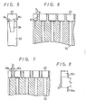
- the stripe is formed at a predetermined position from the reference end portion. It is possible that the shape of the magnetic film is not limited to the stripe shape but the portion lower than the bonded portion may be formed wider as shown in Fig. 6, thus a high sensitivity being achieved.
- a hard film made of Si0 2 , Si 3 N 4 Al 2 O 3 , ZrO 2 or the like so as to have a thickness of about 0.1 ⁇ m to 3 ⁇ m by sputtering, vacuum evaporation, ion plating or the like as a protection film.
- the magnetic thin film is etched by using a photolithography technique to be a stripe-shaped magnetic film with a predetermined width and making a pair in correspondence with the respective recording and reproducing magnetic films. Further, on the above magnetic film is deposited a hard film such as Si0 2 , Si 3 N 4 , Al 2 O 3 , Zro 2 and so on to have a thickness of about 0.1 pm to 3 ⁇ m by sputtering, vacuum evaporation, ion plating or the like as a protection film.
- the shape of the magnetic film for tunnel erase may be formed as shown in Fig. 7.
- Fig. 8 shows a mutual positional relation between the recording and reproducing main magnetic pole 10 and the main magnetic poles 18a, 18b for tunnel erase.
- the width Tl of the recording and reproducing main magnetic pole 10 is made wider than the spacing between the main magnetic poles 18a and 18b for tunnel erase.
- the track end is erased by the main magnetic poles 18a, 18b for tunnel erase.
- the track width finally recorded becomes equal to the spacing To between the main magnetic poles 18a, 18b for tunnel erase the positioning between the recording and reproducing main magnetic pole 10 and the main magnetic poles 18a, 18b for tunnel erase must be carried out with high precision.
- the recording and reproducing main magnetic pole 10 is positioned from the end portion of the substrate with high precision and then, the main magnetic poles 18a, 18b for tunnel erase are positioned on the basis of the reference end.
- the reference side surface has to have a right angle and the edge thereof must be sharp.
- a transparent substrate it is sufficient that any one of the non-magnetic block member-22 or 23 is transparent
- the second patterning of the magnetic pole is carried out, the position of the pattern is confirmed from the back side so as to carry out the positioning.
- a non-magnetic plate shape block 31 and a magnetic material block 32 are prepared. While as the non-magnetic plate block 31 a material similar to the non-magnetic block 23 as shown in Fig. 4 is used, the material for the non-magnetic plate block is not limited particularly if the non-magnetic material is hard, dense and has an thermal expansion coefficient substantially same as that of ferrite. Further, the magnetic material block 32 can be constructed by Mn-Zn series ferrite, Ni-Zn-series ferrite and the like. Each one surface of the non-magnetic plate shape block 31 and the magnetic material block 32 is mirror-polished.
- grooves 33 are formed on the mirror-polished surface 32a of the magnetic material block 32 with a predetermined spacing. Under this condition, the mirror-polished surface 31a of the non-magnetic plate block 31 is opposed to and then bonded to the mirror-polished surface 32a of the magnetic material block 32.
- melt bonding by glass organic bonding agent such as an epoxy adhesives or the like, or inorganic bonding agent 34 such as a water glass and so on
- melt bonding by glass Since the melt bonding by glass is sometimes carried out again in the later process, glass having so high melting temperature as not to be melted by the second melt bonding is employed.
- a bonded member 35 formed of the non-magnetic plate shape block 31 and the magnetic material block 32 is cut out along the surfaces shown by one-dot chain lines ml, m2,m3 ... across the non-magnetic plate shape block 31 and the magnetic material block 32 to have a predetermined thickness, thus one complex block 36 being produced.
- this complex block 36 is mirror-polished. At that time, in order to achieve high sensitivity, it is desirable that similarly to the case of Fig. 4D, the thickness of the portion which will become an auxiliary core 36b is made as thin as possible so far as mechanical strength upon manufacturing is permitted.
- This complex block is bonded to the both mirror-polished surfaces shown in Fig. 4E by melt bonding by glass, organic adhesive agent such as epoxy resin and so on, inorganic adhesive agent such as water glass and the like (Fig. 4G). Thereafter,'the complex block is cut into each magnetic transducer head and the contact surface thereof is polished and a winding is wound thereof, thus the magnetic transducer head as shown in Fig. 2 being produced.
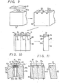
- the patterning of the magnetic pole is carried out on both sides'of the central block, it is possible that the recording and reproducing main magnetic pole 10 and the main magnetic poles 18a, 18b for tunnel erase are respectively patterned on the sides of the complex blocks bonded to the both sides and then they are bonded to the central block which was formed in Fig. 4D. In this case, it is difficult to match the recording and reproducing main magnetic pole 10 and the main magnetic poles 18a, 18b for tunnel erase to one another in position.
- Fig. 10 is a cross-sectional view illustrating such magnetic transducer head.
- the central block with the thin film of magnetic material is the same as_that in Fig. 4 and the blocks at both sides are formed as shown in Fig. 11.
- Other manufacturing procedures are the same as those of Fig. 4.
- the main magnetic pole 10 for recording and reproducing must reduce the thickness of the magnetic pole and the spacing between the magnetic transducer head and the magnetic tape must be made as small as possible.
- the magnetic pole for tunnel erase can carry out the DC erase, the thickness of its magnetic pole can be increased and the problem of the spacing is not so important as the main magnetic pole 10 for recording and reproducing. Therefore, such a magnetic transducer head is considered that a main magnetic pole for recording and reproducing is disposed in the central portion which provides a satisfactory contact with the magnetic tape (Fig. 12).
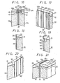
- the center block is formed such that the winding aperture and the cut-out are inclined as shown in Fig. 13.
- the blocks at both sides of the center block can be formed in accordance with Fig. 11.
- the impedance of the coil is as small as possible.
- the impedance of the coil greatly depends on the cross section area of the ferrite core within the coil.
- the width (in the track width direction) of the ferrite core within the coil is equal to the thickness of the magnetic transducer head.
- the portion of the auxiliary core which is required in practice is the portion opposing to the main magnetic pole film.
- the center block can be formed by the following method other than the method shown in Fig. 4. As shown in Fig. 14, a winding groove 24 is formed on the non-magnetic material block 22 and the upper portion thereof is filled with glass 25 (after the groove 24 is covered with a non-magnetic material plate 26 of the same quality, a glass rod 25a is inserted thereinto and melt by heat so as to form a bridge by glass). Then, the center block is cut into respective blocks and the side surface of each block is mirror-polished and thus the central block being formed.
- the characteristic of this block lies in that the surfaces to be mirror-polished are made of the same material and the bonded portion thereof is never exposed to the mirror-polished surface unlike the center block as shown in Fig. 4.
- FIG. 15 is a cross-sectional view illustrating a magnetic transducer head which is provided by this central block . Since the glass 25 is exposed on the contact surface, this magnetic transducer head has a defect that this glass portion is concaved little and is apt to be scratched. Consequently, the contact surface must be mirror-polished with great care.
- the complex magnetic transducer head of single magnetic pole type for perpendicular mode recording is used as the record and reproduce magnetic head of, for example, the flexible disc apparatus to carry out the recording on the magnetic recording medium 11
- a record signal is supplied to the coil 17 of the main magnetic pole 10 and the magnetic recording is carried out by the main magnetic pole 10
- an erase current (DC) is supplied to the erasing coil 21 of the main magnetic poles 18a, 18b for tunnel erase to thereby erase the both sides of the record track.
- the portions which need the-mirror-polishing are formed on the common plane at all times (for example, there is required no process for mirror-polishing two parallel surfaces which have a step therebetween) so that the manufacturing process becomes easier.
- the bonded surface is always formed on the common plane, the bonded film can be made extremely thin and the bonding thereof is very easy.
- the main magnetic pole made of magnetic thin film is formed by sputtering, vacuum evaporation, ion plating, plating and the like, its thickness can be controlled easily.
- the track width of the track can be made narrow with ease and can be manufacuured with high precision.
- the recording and reproducing main magnetic pole 10 and the tunnel erase main magnetic poles 18a, 18b can be matched in position with ease.
- the following magnetic transducer head is considered in which the spacing a between the recording and reproducing main magnetic pole 10 and the tunnel erase main magnetic poles 18a, 18b is made smaller to enhance the .xecording and reproducing characteristics.
- This magnetic transducer head will hereinafter be described with reference to Figs. 16 to 27.
- Figs. 16 to 27 like parts corresponding to those in Figs. 1 to 15 are marked with the same references and will not be described in detail.
- reference numeral 37 designates a non-magnetic material member, and the width of the non-magnetic material member 37 in the running direction of the magnetic recording medium is made narrow as compared with the aforementioned example. Accordingly, as shown in Fig. 8, the spacing a between the recording and reproducing main magnetic pole 10 and the tunnel erase main magnetic poles 18a, 18b which are disposed at the both sides of the non-magnetic material member 37 become narrow.
- Reference numeral 18b' designates an auxiliary magnetic pole member which is magnetically connected to the tunnel erase main magnetic poles 18a, 18b at the position remote backwards from the surface on which the magnetic recording medium is transported so as to form a magnetic path curved to the downstream side of the magnetic recording medium.
- the manufacturing process of this embodiment will be described. Similarly to the manufacturing process of the embodiment shown in Fig. 10, the complex block as shown in Fig. 11 is produced. Thereafter, the left-hand side and right-hand side portions of the magnetic transducer head shown in Fig. 16'is produced via the following process.
- a protection film made of SiO 2 , Si 3 N 4 , Al 2 O 3 , Zro 2 and the like is formed on the surface to which the tunnel erase main magnetic pole films are formed so as to have a thickness of about 0.1 pm to 1 ⁇ m by sputtering, vacuum evaporation, ion plating and the like. This protection film is to prevent the permeation of impurity from the substrate.
- the tunnel erase main magnetic pole film permalloy, sendust alloy, an amorphous magnetic alloy such as Co-Zr, Co-Zr-Nb and so on or the like is deposited on the surface by sputtering, vacuum evaporation, ion plating, plating and the like and then subjected to etching treatment using photolithography technique to have a predetermined dimension or the thickness of about 0.1 pm to 5 pm to thereby form the main magnetic poles 18a, 18b.
- the masking is carried out in such a manner that the tunnel erase main magnetic poles 18a, 18b are positioned at the predetermined position from the.high precision surface.
- a protection film 38 a film made of SiO 2 , Si 3 N 4 , Al 2 O 3 , ZrO 2 and the like is deposited thereon to have a thickness of about 0.5 pm to 3 pm by sputtering, vacuum evaporation, ion plating and so on. Then, the non-magnetic material member 37 is bonded thereon so as to isolate the recording and reproducing main magnetic pole 10 and the tunnel erase main magnetic poles 18a, 18b from one another as shown in Fig. 18. preferably, this non-magnetic material member 37 is made of the same material as that of the non-magnetic material guard members 12a, 12c and has a thickness of about 50 pm to 200 ⁇ m.
- the magnetic transducer head of this embodiment becomes the same as that shown in Fig. 10. It may be possible that the non-magnetic material member 37 having a thickness of 50 ⁇ m to 200 ⁇ m is bonded directly or the non-magnetic material member 37 of, for example, 500 ⁇ m thick is bonded and then abraded and polished so as to have a predetermined thickness. Then, there is formed a groove 39 for the tunnel erase coil 21 and the recording and reproducing coil 17 with a predetermined dimension as shown in Fig. 19.
- the magnetic material portion 18' which is formed by the previously formed groove 33 and the groove 39 forms a part of the tunnel erase main magnetic poles.
- the thickness thereof is about 200 ⁇ m to 300 ⁇ m. If the thickness is thinner, the core will be cracked upon forming the groove, while the thickness is too large, the diameter of the erase coil 21 becomes large so that the coil impedance is increased and the recording and reproducing efficiency grows worse.
- a'manufacturing method for producing the left-hand side portion namely, the portion on the side of the recording and reproducing main magnetic pole.
- a high permeability magnetic material film such as permalloy, sendust alloy, amorphous magnetic alloy such as Co-Zr, Co-Zr-Nb and so on which becomes the recording and reproducing main magnetic pole 10 is deposited on the mirror-polished surface and then subjected to etching by using photolithography technique so as to have a predeter- . mined dimension.
- the bonded surface of the magnetic core 13a and the non-magnetic material guard member 12a forms an acute angle relative to the main magnetic pole 10.
- the side surface of the magnetic material block 32 is mirror-polished and further the main magnetic pole surface and the side surface of the magnetic material block are adapted to form a right angle with high precision. Then, the position of the recording and reproducing main magnetic pole 10 is determined in advance in order that when the reference surfaces of the left and right complex blocks are contacted to each other, they are arranged at a predetermined position.
- the two blocks thus made are bonded together by melt bonding by glass, organic adhesive agent such as epoxy resin and the like, inorganic adhesive agent such as water glass and the like (Fig. 21). Then, the contact surface with the magnetic record medium is cylindrically polished to make the magnetic pole film have a predetermined length and the complex block is separately cut into respective magnetic block members. Thereafter, the magnetic block is bonded to a base substrate and subjected to the recording and reproducing wiring treatment and the tunnel erase winding treatment, thus the complex magnetic transducer head of single magnetic pole type for perpendicular mode recording being provided.
- the magnetic path which is magnetically connected to the tunnel erase main magnetic poles 18a, 18b and curved from the tunnel erase main magnetic poles to the downstream of the magnetic recording medium, is formed to secure the winding spacing, it is possible to reduce the distance or spacing between the recording and reproducing main magnetic pole and the tunnel erase main magnetic poles without deteriorating excellent electromagnetic transducer characteristic.
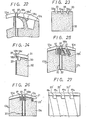
- the magnetic material portion 18b' in the above embodiment is formed as the smooth shape as shown in Fig. 22.
- the magnetic material portion is preferably reinforced by, for example, glass 18c.
- the leakage magnetic flux is decreased and it is possible to alleviate the decline of efficiency which is caused by the fact that the tip end portion of the erase main magnetic pole (portion contacting with the record medium) does not exist on the extension of the center of the coil 21.
- the groove 33 is formed, an edge portion 33a of the groove is cut by the predetermined shape as shown in Fig. 23.
- the reinforcing glass 18c can be simultaneously provided therebetween.
- such smooth shape may be cylindrical shape.
- the portion of the coil 21 of the tunnel erase main magnetic pole is inclined as shown in Fig. 25.
- F ig. 26 shows other embodiment of this invention.
- the groove 33 for the winding of the tunnel erase main magnetic pole in the example shown in Fig. 16 is formed as a cut-out groove 33'.
- the other portions are formed similarly to those in the example shown in Fig. 16.
- This embodiment can achieve the same action and effect as those of the example in Fig. 16 and in addition, there is an advantage that the winding becomes easy.
- the coil on the erase side is formed as a thin film coil on the interface between the magnetic core portion and the guard member of the contact surface and the erasing main magnetic pole is magnetically connected to the magnetic core portion at the center of the thin film coil.
Landscapes
- Engineering & Computer Science (AREA)
- Manufacturing & Machinery (AREA)
- Magnetic Heads (AREA)
Abstract
Applications Claiming Priority (4)
| Application Number | Priority Date | Filing Date | Title |
|---|---|---|---|
| JP4766683A JPS59175013A (ja) | 1983-03-22 | 1983-03-22 | 垂直記録用単磁極型複合磁気ヘツド |
| JP47666/83 | 1983-03-22 | ||
| JP52157/83 | 1983-03-28 | ||
| JP5215783A JPS59177719A (ja) | 1983-03-28 | 1983-03-28 | 垂直記録用単磁極型複合磁気ヘツド |
Publications (3)
| Publication Number | Publication Date |
|---|---|
| EP0139018A1 true EP0139018A1 (fr) | 1985-05-02 |
| EP0139018A4 EP0139018A4 (fr) | 1987-04-28 |
| EP0139018B1 EP0139018B1 (fr) | 1990-06-13 |
Family
ID=26387831
Family Applications (1)
| Application Number | Title | Priority Date | Filing Date |
|---|---|---|---|
| EP84901220A Expired EP0139018B1 (fr) | 1983-03-22 | 1984-03-16 | Assemblage de têtes transductrices magnétiques d'un seul type de pôles magnétiques pour enregistrement perpendiculaire |
Country Status (4)
| Country | Link |
|---|---|
| US (1) | US4858048A (fr) |
| EP (1) | EP0139018B1 (fr) |
| DE (1) | DE3482515D1 (fr) |
| WO (1) | WO1984003788A1 (fr) |
Cited By (1)
| Publication number | Priority date | Publication date | Assignee | Title |
|---|---|---|---|---|
| EP0228688A3 (fr) * | 1985-12-23 | 1988-03-30 | Matsushita Electric Industrial Co., Ltd. | Tête magnétique pour l'enregistrement perpendiculaire |
Families Citing this family (8)
| Publication number | Priority date | Publication date | Assignee | Title |
|---|---|---|---|---|
| US5353170A (en) * | 1993-05-19 | 1994-10-04 | International Business Machines Corporation | Error recovery data storage system and method with two position read verification |
| US20020171975A1 (en) * | 2001-05-15 | 2002-11-21 | Plumer Martin L. | Writing element with no return path |
| JP4519393B2 (ja) * | 2002-04-10 | 2010-08-04 | 新科實業有限公司 | 垂直磁気記録ヘッドおよびその製造方法、ならびに磁気記録装置 |
| US7038882B2 (en) * | 2002-10-03 | 2006-05-02 | Seagate Technology | Low moment-high moment write pole with non-magnetic layer for establishing a magnetic path discontinuity between layers of the write pole |
| US8085498B2 (en) * | 2009-09-17 | 2011-12-27 | Headway Technologies, Inc. | PMR write with flux choking area |
| US8072706B2 (en) * | 2009-10-15 | 2011-12-06 | Tdk Corporation | Magnetic head for perpendicular magnetic recording and method of manufacturing same |
| US8134802B2 (en) * | 2009-10-29 | 2012-03-13 | Headway Technologies, Inc. | Writer and reader arrangements for shingled writing |
| US8295008B1 (en) * | 2011-07-22 | 2012-10-23 | Headway Technologies, Inc. | Magnetic head for perpendicular magnetic recording having a main pole and a shield |
Family Cites Families (5)
| Publication number | Priority date | Publication date | Assignee | Title |
|---|---|---|---|---|
| US4058846A (en) * | 1976-06-21 | 1977-11-15 | International Business Machines Corporation | Grounded transducer for magnetic record disks |
| JPS57162114A (en) * | 1981-03-30 | 1982-10-05 | Sony Corp | Magnetic head |
| JPS58171711A (ja) * | 1982-03-31 | 1983-10-08 | Matsushita Electric Ind Co Ltd | 垂直磁化ヘツド |
| JPS58203612A (ja) * | 1982-05-21 | 1983-11-28 | Seiko Epson Corp | 磁気ヘツド |
| US4541026A (en) * | 1982-07-20 | 1985-09-10 | Vertimag Systems Corporation | Hybrid read-write head for perpendicular recording media |
-
1984
- 1984-03-16 WO PCT/JP1984/000110 patent/WO1984003788A1/fr not_active Ceased
- 1984-03-16 EP EP84901220A patent/EP0139018B1/fr not_active Expired
- 1984-03-16 DE DE8484901220T patent/DE3482515D1/de not_active Expired - Lifetime
-
1987
- 1987-08-10 US US07/085,322 patent/US4858048A/en not_active Expired - Fee Related
Cited By (1)
| Publication number | Priority date | Publication date | Assignee | Title |
|---|---|---|---|---|
| EP0228688A3 (fr) * | 1985-12-23 | 1988-03-30 | Matsushita Electric Industrial Co., Ltd. | Tête magnétique pour l'enregistrement perpendiculaire |
Also Published As
| Publication number | Publication date |
|---|---|
| EP0139018A4 (fr) | 1987-04-28 |
| US4858048A (en) | 1989-08-15 |
| EP0139018B1 (fr) | 1990-06-13 |
| DE3482515D1 (de) | 1990-07-19 |
| WO1984003788A1 (fr) | 1984-09-27 |
Similar Documents
| Publication | Publication Date | Title |
|---|---|---|
| US4635153A (en) | Magnetic transducer head | |
| US4858048A (en) | Complex magnetic transducer head of single magnetic pole type for perpendicular mode recording | |
| JPH0334114A (ja) | 浮上型磁気ヘッド | |
| US4768121A (en) | Magnetic head formed by composite main pole film and winding core for perpendicular magnetic recording | |
| JPH0785289B2 (ja) | 磁気ヘッドの製造方法 | |
| KR900004743B1 (ko) | 수직 자기기록용 자기헤드 및 그 제조방법 | |
| JPH0773411A (ja) | データカートリッジ用磁気ヘッド装置 | |
| EP0602486B1 (fr) | Tête magnétique flottante | |
| EP0175800A1 (fr) | Tête de transducteur magnétique | |
| KR900004741B1 (ko) | 수직 자기기록용 자기헤드 및 그 제조방법 | |
| KR940004485B1 (ko) | 복합형 자기헤드와 그 제조방법 | |
| JPS59175013A (ja) | 垂直記録用単磁極型複合磁気ヘツド | |
| JP2887204B2 (ja) | 狭トラック磁気ヘッドの製造方法 | |
| EP0137049A1 (fr) | Tete d'enregistrement magnetique perpendiculaire | |
| JPS634243B2 (fr) | ||
| JPS59201209A (ja) | 複合型磁気ヘツド | |
| JPS62257609A (ja) | 磁気ヘツドの補強構造 | |
| JPH1074303A (ja) | 磁気ヘッドの製造方法及び磁気ヘッド | |
| JPS59177719A (ja) | 垂直記録用単磁極型複合磁気ヘツド | |
| JPS60191406A (ja) | 垂直記録再生磁気ヘツド | |
| JPS6226618A (ja) | 薄膜磁気ヘツド | |
| JPS59177714A (ja) | 垂直記録用単磁極型複合磁気ヘツド | |
| JPS6247810A (ja) | 磁気コアおよびその製造方法 | |
| JPS60119610A (ja) | 垂直記録用単磁極型磁気ヘツド | |
| JPS6216209A (ja) | 単磁極型磁気ヘツド |
Legal Events
| Date | Code | Title | Description |
|---|---|---|---|
| PUAI | Public reference made under article 153(3) epc to a published international application that has entered the european phase |
Free format text: ORIGINAL CODE: 0009012 |
|
| 17P | Request for examination filed |
Effective date: 19841209 |
|
| AK | Designated contracting states |
Designated state(s): DE FR GB NL |
|
| A4 | Supplementary search report drawn up and despatched |
Effective date: 19870428 |
|
| 17Q | First examination report despatched |
Effective date: 19881024 |
|
| GRAA | (expected) grant |
Free format text: ORIGINAL CODE: 0009210 |
|
| AK | Designated contracting states |
Kind code of ref document: B1 Designated state(s): DE FR GB NL |
|
| REF | Corresponds to: |
Ref document number: 3482515 Country of ref document: DE Date of ref document: 19900719 |
|
| ET | Fr: translation filed | ||
| PLBE | No opposition filed within time limit |
Free format text: ORIGINAL CODE: 0009261 |
|
| STAA | Information on the status of an ep patent application or granted ep patent |
Free format text: STATUS: NO OPPOSITION FILED WITHIN TIME LIMIT |
|
| 26N | No opposition filed | ||
| PGFP | Annual fee paid to national office [announced via postgrant information from national office to epo] |
Ref country code: FR Payment date: 19940310 Year of fee payment: 11 |
|
| PGFP | Annual fee paid to national office [announced via postgrant information from national office to epo] |
Ref country code: GB Payment date: 19940315 Year of fee payment: 11 |
|
| PGFP | Annual fee paid to national office [announced via postgrant information from national office to epo] |
Ref country code: NL Payment date: 19940331 Year of fee payment: 11 |
|
| PGFP | Annual fee paid to national office [announced via postgrant information from national office to epo] |
Ref country code: DE Payment date: 19940530 Year of fee payment: 11 |
|
| PG25 | Lapsed in a contracting state [announced via postgrant information from national office to epo] |
Ref country code: GB Effective date: 19950316 |
|
| PG25 | Lapsed in a contracting state [announced via postgrant information from national office to epo] |
Ref country code: NL Effective date: 19951001 |
|
| GBPC | Gb: european patent ceased through non-payment of renewal fee |
Effective date: 19950316 |
|
| PG25 | Lapsed in a contracting state [announced via postgrant information from national office to epo] |
Ref country code: FR Free format text: LAPSE BECAUSE OF NON-PAYMENT OF DUE FEES Effective date: 19951130 |
|
| NLV4 | Nl: lapsed or anulled due to non-payment of the annual fee |
Effective date: 19951001 |
|
| PG25 | Lapsed in a contracting state [announced via postgrant information from national office to epo] |
Ref country code: DE Effective date: 19951201 |
|
| REG | Reference to a national code |
Ref country code: FR Ref legal event code: ST |