EP0147619A2 - Strangführer für eine Verlegevorrichtung zum Aufwickeln von Kabeln auf einer Trommel mit Endflanschen - Google Patents
Strangführer für eine Verlegevorrichtung zum Aufwickeln von Kabeln auf einer Trommel mit Endflanschen Download PDFInfo
- Publication number
- EP0147619A2 EP0147619A2 EP84114024A EP84114024A EP0147619A2 EP 0147619 A2 EP0147619 A2 EP 0147619A2 EP 84114024 A EP84114024 A EP 84114024A EP 84114024 A EP84114024 A EP 84114024A EP 0147619 A2 EP0147619 A2 EP 0147619A2
- Authority
- EP
- European Patent Office
- Prior art keywords
- cable
- reel
- guiding device
- guide
- traverse arm
- Prior art date
- Legal status (The legal status is an assumption and is not a legal conclusion. Google has not performed a legal analysis and makes no representation as to the accuracy of the status listed.)
- Granted
Links
Images


Classifications
-
- B—PERFORMING OPERATIONS; TRANSPORTING
- B65—CONVEYING; PACKING; STORING; HANDLING THIN OR FILAMENTARY MATERIAL
- B65H—HANDLING THIN OR FILAMENTARY MATERIAL, e.g. SHEETS, WEBS, CABLES
- B65H54/00—Winding, coiling, or depositing filamentary material
- B65H54/02—Winding and traversing material on to reels, bobbins, tubes, or like package cores or formers
- B65H54/28—Traversing devices; Package-shaping arrangements
- B65H54/2848—Arrangements for aligned winding
- B65H54/2851—Arrangements for aligned winding by pressing the material being wound against the drum, flange or already wound material, e.g. by fingers or rollers; guides moved by the already wound material
Definitions
- This invention relates to a guiding device for a distributor for winding a cable on a flanged reel, which guiding device comprises
- U .S. Patent Specification 3,951,355 discloses a distributor which is provided with a guiding device for guiding the winding of a cable.
- the guiding device comprises a traverse arm supported by a traversing device, whereby the cable passes along one side of said arm towards the end thereof.
- a number of rolls provided with peripheral grooves and serving as supporting means are mounted for the cable at the end of the traverse arm. The support rolls are pressed against the cable from opposite sides, thus determining the path of movement of the cable.
- a press roll is mounted at the end of the traverse arm, which roll presses the cable sideways against the flange of the reel or the preceding cable revolution.
- a detector of a capacitance type is provided at the end of the traverse arm, which detector detects the vicinity of the flange without contacting said flange and sends electrically proper guiding impulses to the traversing device for the traverse arm.
- the most important disadvantage of the known guiding device is that the guiding head of the device is of a complex construction as well as liable to damage.
- the rolls guiding the cable must be accurately mounted on the traverse arm without any clearance and each cable size requires roll provided with peripheral grooves of a corresponding size.
- Both the rolls and the detector project from the side of the traverse arm towards the flange of the reel. This causes a risk that a protruding board or other distortion of the flange of a deformed wooden reel may hit the set of rolls during the rotation of the reel, thus causing damage to the rolls and the detector.
- the object of this invention is to provide a guiding device which avoids the above disadvantages and enables regular winding of a cable even on a deformed reel.
- This object is achieved by means of a guiding device according to the invention, which is characterized in that the guiding means of the traverse arm comprises at least one guide surface eccentrically positioned with respect to said path of movement for contacting the flange of the reel, whereby the horizontal distance of said guide surface from said path of movement equals to one and a half times the diameter of the cable to be wound in a first rotated position of the traverse arm and to half the diameter of the cable in a second rotated position of the traverse arm.
- the invention is based on the idea that the flange itself guides the traverse arm by means of a mechanical contact between said arm and said flange in the vicinity of each of the two flanges of the reel.
- the contact between the traverse arm and the flange is maintained not only during the first revolution of the cable i.e. the revolution nearest the flange, but also during the following revolution, whereby the traverse arm can be spaced apart from the flange a distance equal to the diameter of the cable by means of said guide surface so that when the first revolution has been completed, the cable can be positively displaced so as to be wound accurately beside the first revolution.
- the traverse arm follows the flange by means of a mechanical contact, it is ensured that the cable is guided to run accurately along the desired path with respect to the flange also in deformed reels, and, further, to be displaced up on the correct revolution at such difficult points as mentioned above. Consequently, the guiding device does not require any detector nor any electric circuit or sensing of the angle movement of the reel in order to guide the cable in the vicinity of the flanges.
- the traverse arm is capable of following also a deformed twisted flange and the guide surface of said arm is not susceptible to pushes or strikes, because it does not comprise any projecting parts and because the surface of the required eccentric element can be bevelled where necessary.
- the traverse arm is formed by a tube, in which the cylindrical hole of the tube forms a guideway for the cable to be wound. No rolls which are difficult to manufacture are thus required for guiding the cable winding but a simple tube will suffice.
- Such simple tubes having different diameters and corresponding simple eccentric elements can without any major costs be kept in storage for cables of different sizes. Replacing one guide tube with another is an extremely simple operation.
- Figure 1 of the drawings illustrates a distributor which comprises a base 1, in which a vertically displaceable adjusting column 2 is mounted, which column supports a horizontally displaceable traversing carriage 3.
- Said carriage supports a feeding device 4 for a cable 5 to be wound and a guiding device 6, which is pivotable around both a vertical 7 and a horizontal 8 shaft in a manner similar to a universal joint.
- the guiding device guides the cable to be wound on a reel 9 comprising a drum 10 and two flanges 11, 12.
- the guiding device 6 comprises a sleeve-like support 13, which is mounted on the carriage 3 by means of a fork-like retainer 14. Said retainer is pivotable around the vertical axle 7 by means of a pressure medium cylinder 15.
- a supporting bushing 16 is rotatably mounted inside the support and a traverse tube 17 is fastened to said bushing co-axially with the axis of rotation of the supporting bushing.
- An external tooth ring 18 is fastened to said supporting bushing and a rotating motor 19 is mounted on the support 13 in engagement with said tooth ring.
- a guide head 20 is fastened at the outer end of the traverse tube, said guide head comprising an eccentric element 21 which is provided with a guide hole 22 co-axial with the traverse tube.
- the diameter D of said hole corresponds to the diameter of the axial hole 23 of the traverse tube.
- Said eccentric element further comprises a cylindrical guide surface 24, the radius R of which equals to one and a half times the diameter of the guide hole and the centre of which is displaced from the centre of the guide hole by a distance essentially equal to the diameter of the guide hole so that the guide surface nearly contacts the outer periphery of the guide hole with a small wall thickness.
- the eccentric element thus forms two diametrally opposite guide cams 25, 26. Both ends of the eccentric element are formed with bevelled surfaces.
- the diameter of the axial hole of the traverse tube exceeds the diameter of the cable to be wound only so much that it is possible for the cable to slide easily through the tube.
- the centre line of the hole of the tube thus forms the path of movement L along which the axis of the cable to be wound moves during the winding operation.
- the winding of the cable is carried out as follows:
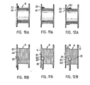
- the traversing device raises the traverse tube by the height of the diameter of the cable, whereby the position of the guide head remains unchanged, as shown in Figures 10A-10B.
- the cable is thus guided up on the last revolution A1 to form the first revolution B1 of the second layer B so that said first revolution is positioned close to the flange.
- the rotating motor rotates the traverse tube over an angle of 90 0 back to the normal winding position.
- One guide cam 25 of the eccentric element is thereby turned against the flange to force the guide head to move in the horizontal plane away from the flange so that the guide hole is positioned at a distance equal to the diameter of the cable from the preceding position.
- the new position II of the guide head is shown in Figures 11A-11B. The guide head thereby deviates the cable sidewaros an amount equal to the diameter of the cable so that the cable is not wound up on said first revolution B1 but beside it to form the second revolution B2 of the second layer B.
- the traversing device again displaces the guide head a distance equal to the diameter of the cable away from the flange, whereby the guide head is released from contact with the flange.
- the revolutions of the second layer have thus been properly started and the guide head continues the guiding operation by means of the normal distribution control of the traversing device, as shown in Figures 12A-12B.
- the rotating motor again rotates the guide head over an angle of 90° but this time in such a direction that the guide hole of the guide head is positioned towards the other flange 12. Thereafter, the operation is similar to that described above, and in the vicinity of the flange, the other guide cam 26 of the eccentric body is pressed against the flange 12 when the second revolution of the third layer is to be deviated to a distance equal to the diameter of the cable away from the flange.
- the guide head according to the invention may vary within the scope of the claims. Accordingly, the traverse tube can be made expansive so as to enable a cable with an uneven surface to pass through the tube.
Landscapes
- Guides For Winding Or Rewinding, Or Guides For Filamentary Materials (AREA)
- Storage Of Web-Like Or Filamentary Materials (AREA)
- Pens And Brushes (AREA)
- Credit Cards Or The Like (AREA)
- Medicines Containing Antibodies Or Antigens For Use As Internal Diagnostic Agents (AREA)
- Winding Filamentary Materials (AREA)
Priority Applications (1)
| Application Number | Priority Date | Filing Date | Title |
|---|---|---|---|
| AT84114024T ATE40543T1 (de) | 1983-11-22 | 1984-11-20 | Strangfuehrer fuer eine verlegevorrichtung zum aufwickeln von kabeln auf einer trommel mit endflanschen. |
Applications Claiming Priority (2)
| Application Number | Priority Date | Filing Date | Title |
|---|---|---|---|
| FI834272 | 1983-11-22 | ||
| FI834272A FI67350C (fi) | 1983-11-22 | 1983-11-22 | Styranordning foer en foerdelningsapparat foer spolning av en kabel pao en flaensfoersedd trumma |
Publications (3)
| Publication Number | Publication Date |
|---|---|
| EP0147619A2 true EP0147619A2 (de) | 1985-07-10 |
| EP0147619A3 EP0147619A3 (en) | 1986-08-20 |
| EP0147619B1 EP0147619B1 (de) | 1989-02-01 |
Family
ID=8518108
Family Applications (1)
| Application Number | Title | Priority Date | Filing Date |
|---|---|---|---|
| EP84114024A Expired EP0147619B1 (de) | 1983-11-22 | 1984-11-20 | Strangführer für eine Verlegevorrichtung zum Aufwickeln von Kabeln auf einer Trommel mit Endflanschen |
Country Status (6)
| Country | Link |
|---|---|
| US (1) | US4592521A (de) |
| EP (1) | EP0147619B1 (de) |
| JP (1) | JPS60188274A (de) |
| AT (1) | ATE40543T1 (de) |
| DE (1) | DE3476532D1 (de) |
| FI (1) | FI67350C (de) |
Cited By (4)
| Publication number | Priority date | Publication date | Assignee | Title |
|---|---|---|---|---|
| EP0176227A3 (de) * | 1984-08-23 | 1987-04-29 | Taliana S.A. | Verfahren und Vorrichtung zum Aufwickeln eines Haarflordichtungsstreifens |
| WO1995018058A1 (en) * | 1993-12-29 | 1995-07-06 | Skaltek Ab | Guiding device for winding or unwinding a line, e.g. a cable or a rope, onto or from a reel |
| CN104555565A (zh) * | 2014-09-30 | 2015-04-29 | 太仓市上阳机械有限公司 | 一种简易收线装置 |
| WO2015113763A1 (de) * | 2014-01-28 | 2015-08-06 | Gabo Systemtechnik Gmbh | Verlegearm für eine vorrichtung zum wickeln eines strangförmigen wickelguts |
Families Citing this family (11)
| Publication number | Priority date | Publication date | Assignee | Title |
|---|---|---|---|---|
| AU7588287A (en) * | 1986-06-10 | 1988-01-11 | Robert L. Schneider | Service lubricating of metal haulage cables |
| GB8614605D0 (en) * | 1986-06-16 | 1986-07-23 | Mackie & Sons Ltd J | Yarn winding machines |
| DE3728995A1 (de) * | 1987-08-29 | 1989-03-09 | Lapp Kg U I | Vorrichtung zum herstellen von ringbunden aus draht oder dergleichen |
| SE466602B (sv) * | 1990-06-15 | 1992-03-09 | Maillefer Nokia Holding | Anordning vid en upprullningsmaskin foer en kabel eller liknande straengformat gods |
| DE4243595A1 (de) * | 1992-12-22 | 1994-06-23 | Mag Masch App | Verfahren und Vorrichtung zum Aufwickeln von Rundmaterial auf eine mit Endflanschen versehene Spule |
| IT1302793B1 (it) * | 1998-11-04 | 2000-09-29 | Danieli & C Ohg Sp | Dispositivo per formare le spire in una macchinarocchettatrice di prodotti laminati |
| US20030006034A1 (en) * | 2001-07-05 | 2003-01-09 | Heartland Rig International, Llc | Coiled tubing level wind system |
| ITUD20040077A1 (it) * | 2004-04-14 | 2004-07-14 | Simac Spa | Macchina bobinatrice universale per filo |
| US20130200202A1 (en) * | 2012-02-02 | 2013-08-08 | John Jeddore | Rope coiler |
| JP2014114143A (ja) * | 2012-12-12 | 2014-06-26 | Hitachi Metals Ltd | 線材の巻取り方法および線材の巻取り装置 |
| JP2022525346A (ja) * | 2019-03-14 | 2022-05-12 | リーレックス パッケージング ソリューションズ, インコーポレーテッド | 調整可能フィラメント材案内装置 |
Family Cites Families (9)
| Publication number | Priority date | Publication date | Assignee | Title |
|---|---|---|---|---|
| GB1194825A (en) * | 1966-07-06 | 1970-06-10 | Marshall Richards Barcro Ltd | Improvements in and relating to Spooling of Filamentary Materials |
| US3722827A (en) * | 1971-02-12 | 1973-03-27 | Gearworks B Ltd | Fairlead carriage |
| AU495293B2 (en) * | 1974-08-27 | 1976-03-04 | Sumitomo Electric Industries, Ltd. | Automatic cable winding apparatus |
| US3997128A (en) * | 1974-12-18 | 1976-12-14 | The Furukawa Electric Co., Ltd. | Wire take up apparatus |
| US4150801A (en) * | 1975-10-30 | 1979-04-24 | Kobe Steel, Ltd. | Automatic winding machine for wire-like object |
| US4179083A (en) * | 1976-02-25 | 1979-12-18 | The Furukawa Electric Co., Ltd. | Wire forcing device for a wire take up apparatus |
| FR2357462A1 (fr) * | 1976-02-25 | 1978-02-03 | Furukawa Electric Co Ltd | Dispositif applicateur de fil pour un dispositif d'enroulement de fil metallique et notamment de cable electrique |
| JPS5439589A (en) * | 1977-09-05 | 1979-03-27 | Nippon Telegr & Teleph Corp <Ntt> | Photo electric converter |
| CA1164851A (en) * | 1981-08-17 | 1984-04-03 | Ali Pan | Reeling of cable |
-
1983
- 1983-11-22 FI FI834272A patent/FI67350C/fi not_active IP Right Cessation
-
1984
- 1984-11-20 EP EP84114024A patent/EP0147619B1/de not_active Expired
- 1984-11-20 DE DE8484114024T patent/DE3476532D1/de not_active Expired
- 1984-11-20 AT AT84114024T patent/ATE40543T1/de not_active IP Right Cessation
- 1984-11-20 US US06/673,478 patent/US4592521A/en not_active Expired - Fee Related
- 1984-11-22 JP JP59247891A patent/JPS60188274A/ja active Pending
Cited By (4)
| Publication number | Priority date | Publication date | Assignee | Title |
|---|---|---|---|---|
| EP0176227A3 (de) * | 1984-08-23 | 1987-04-29 | Taliana S.A. | Verfahren und Vorrichtung zum Aufwickeln eines Haarflordichtungsstreifens |
| WO1995018058A1 (en) * | 1993-12-29 | 1995-07-06 | Skaltek Ab | Guiding device for winding or unwinding a line, e.g. a cable or a rope, onto or from a reel |
| WO2015113763A1 (de) * | 2014-01-28 | 2015-08-06 | Gabo Systemtechnik Gmbh | Verlegearm für eine vorrichtung zum wickeln eines strangförmigen wickelguts |
| CN104555565A (zh) * | 2014-09-30 | 2015-04-29 | 太仓市上阳机械有限公司 | 一种简易收线装置 |
Also Published As
| Publication number | Publication date |
|---|---|
| ATE40543T1 (de) | 1989-02-15 |
| FI834272A0 (fi) | 1983-11-22 |
| FI67350B (fi) | 1984-11-30 |
| EP0147619A3 (en) | 1986-08-20 |
| DE3476532D1 (en) | 1989-03-09 |
| US4592521A (en) | 1986-06-03 |
| FI67350C (fi) | 1985-03-11 |
| JPS60188274A (ja) | 1985-09-25 |
| EP0147619B1 (de) | 1989-02-01 |
Similar Documents
| Publication | Publication Date | Title |
|---|---|---|
| EP0147619B1 (de) | Strangführer für eine Verlegevorrichtung zum Aufwickeln von Kabeln auf einer Trommel mit Endflanschen | |
| KR100235080B1 (ko) | 웨브를 감는방법 및 장치 | |
| US3687385A (en) | Winding device for a cable, rope or the like | |
| US4783980A (en) | Apparatus for making helically wound interlocked flexible pipe | |
| US3945580A (en) | Wire-winding machine | |
| EP0516696B1 (de) | Führungsvorrichtung für eine maschine zum aufwickeln drahtförmiger güter | |
| US3259336A (en) | Coil winding machine | |
| US4571974A (en) | Bending machine for wire or strip material | |
| EP0132388B1 (de) | Aufwickeln von Bandmaterial zu Ballen | |
| JPS6364376B2 (de) | ||
| CN216549385U (zh) | 排绳装置及自动排绳系统 | |
| US6974104B2 (en) | Method for winding onto a toroidal core | |
| JPS6118502B2 (de) | ||
| US5236140A (en) | Process and apparatus for wrapping up articles, particularly bobbins provided with electrical winding, with tape | |
| JPH05229733A (ja) | 線材の拘束装置 | |
| JPH07201601A (ja) | コイルおよびコイル製造方法ならびにコイル製造装置 | |
| JPS6142707B2 (de) | ||
| SU1555717A1 (ru) | Способ намотки провода | |
| JPS63241912A (ja) | 特に双極形または四極形磁石に適するコイル用の自動式巻線成形装置 | |
| JPS6240271B2 (de) | ||
| JPS6047184B2 (ja) | 線条体のトレ−巻取装置における巻付半径検出装置 | |
| JPH02260B2 (de) | ||
| US3690288A (en) | Apparatus for processing coiled tubing having turns prebent to varying radii of curvature | |
| JPS61234018A (ja) | 巻鉄心製造装置におけるガイド装置 | |
| SU1048549A1 (ru) | Намоточное устройство к станку дл наложени ленточной изол ции |
Legal Events
| Date | Code | Title | Description |
|---|---|---|---|
| PUAI | Public reference made under article 153(3) epc to a published international application that has entered the european phase |
Free format text: ORIGINAL CODE: 0009012 |
|
| AK | Designated contracting states |
Designated state(s): AT CH DE FR GB LI SE |
|
| PUAL | Search report despatched |
Free format text: ORIGINAL CODE: 0009013 |
|
| AK | Designated contracting states |
Kind code of ref document: A3 Designated state(s): AT CH DE FR GB LI SE |
|
| 17P | Request for examination filed |
Effective date: 19870122 |
|
| 17Q | First examination report despatched |
Effective date: 19871020 |
|
| GRAA | (expected) grant |
Free format text: ORIGINAL CODE: 0009210 |
|
| AK | Designated contracting states |
Kind code of ref document: B1 Designated state(s): AT CH DE FR GB LI SE |
|
| REF | Corresponds to: |
Ref document number: 40543 Country of ref document: AT Date of ref document: 19890215 Kind code of ref document: T |
|
| REF | Corresponds to: |
Ref document number: 3476532 Country of ref document: DE Date of ref document: 19890309 |
|
| ET | Fr: translation filed | ||
| PLBE | No opposition filed within time limit |
Free format text: ORIGINAL CODE: 0009261 |
|
| STAA | Information on the status of an ep patent application or granted ep patent |
Free format text: STATUS: NO OPPOSITION FILED WITHIN TIME LIMIT |
|
| 26N | No opposition filed | ||
| PGFP | Annual fee paid to national office [announced via postgrant information from national office to epo] |
Ref country code: GB Payment date: 19921106 Year of fee payment: 9 |
|
| PGFP | Annual fee paid to national office [announced via postgrant information from national office to epo] |
Ref country code: SE Payment date: 19921111 Year of fee payment: 9 |
|
| PGFP | Annual fee paid to national office [announced via postgrant information from national office to epo] |
Ref country code: FR Payment date: 19921117 Year of fee payment: 9 |
|
| PGFP | Annual fee paid to national office [announced via postgrant information from national office to epo] |
Ref country code: AT Payment date: 19921130 Year of fee payment: 9 |
|
| PGFP | Annual fee paid to national office [announced via postgrant information from national office to epo] |
Ref country code: CH Payment date: 19921224 Year of fee payment: 9 |
|
| PGFP | Annual fee paid to national office [announced via postgrant information from national office to epo] |
Ref country code: DE Payment date: 19930129 Year of fee payment: 9 |
|
| PG25 | Lapsed in a contracting state [announced via postgrant information from national office to epo] |
Ref country code: GB Effective date: 19931120 Ref country code: AT Effective date: 19931120 |
|
| PG25 | Lapsed in a contracting state [announced via postgrant information from national office to epo] |
Ref country code: SE Effective date: 19931121 |
|
| PG25 | Lapsed in a contracting state [announced via postgrant information from national office to epo] |
Ref country code: LI Effective date: 19931130 Ref country code: CH Effective date: 19931130 |
|
| GBPC | Gb: european patent ceased through non-payment of renewal fee |
Effective date: 19931120 |
|
| PG25 | Lapsed in a contracting state [announced via postgrant information from national office to epo] |
Ref country code: FR Effective date: 19940729 |
|
| REG | Reference to a national code |
Ref country code: CH Ref legal event code: PL |
|
| PG25 | Lapsed in a contracting state [announced via postgrant information from national office to epo] |
Ref country code: DE Effective date: 19940802 |
|
| REG | Reference to a national code |
Ref country code: FR Ref legal event code: ST |
|
| EUG | Se: european patent has lapsed |
Ref document number: 84114024.7 Effective date: 19940610 |