EP0151184A1 - Vorrichtung zum betonen und anzeigen eines auf einer bestimmten adresseaufgespeicherten programmteiles einer numerischen steuerung - Google Patents
Vorrichtung zum betonen und anzeigen eines auf einer bestimmten adresseaufgespeicherten programmteiles einer numerischen steuerung Download PDFInfo
- Publication number
- EP0151184A1 EP0151184A1 EP84901414A EP84901414A EP0151184A1 EP 0151184 A1 EP0151184 A1 EP 0151184A1 EP 84901414 A EP84901414 A EP 84901414A EP 84901414 A EP84901414 A EP 84901414A EP 0151184 A1 EP0151184 A1 EP 0151184A1
- Authority
- EP
- European Patent Office
- Prior art keywords
- command
- address
- display
- command program
- character
- Prior art date
- Legal status (The legal status is an assumption and is not a legal conclusion. Google has not performed a legal analysis and makes no representation as to the accuracy of the status listed.)
- Granted
Links
Images


Classifications
-
- G—PHYSICS
- G05—CONTROLLING; REGULATING
- G05B—CONTROL OR REGULATING SYSTEMS IN GENERAL; FUNCTIONAL ELEMENTS OF SUCH SYSTEMS; MONITORING OR TESTING ARRANGEMENTS FOR SUCH SYSTEMS OR ELEMENTS
- G05B19/00—Program-control systems
- G05B19/02—Program-control systems electric
- G05B19/18—Numerical control [NC], i.e. automatically operating machines, in particular machine tools, e.g. in a manufacturing environment, so as to execute positioning, movement or co-ordinated operations by means of program data in numerical form
- G05B19/4093—Numerical control [NC], i.e. automatically operating machines, in particular machine tools, e.g. in a manufacturing environment, so as to execute positioning, movement or co-ordinated operations by means of program data in numerical form characterised by part programming, e.g. entry of geometrical information as taken from a technical drawing, combining this with machining and material information to obtain control information, named part program, for the NC machine
-
- G—PHYSICS
- G05—CONTROLLING; REGULATING
- G05B—CONTROL OR REGULATING SYSTEMS IN GENERAL; FUNCTIONAL ELEMENTS OF SUCH SYSTEMS; MONITORING OR TESTING ARRANGEMENTS FOR SUCH SYSTEMS OR ELEMENTS
- G05B2219/00—Program-control systems
- G05B2219/30—Nc systems
- G05B2219/35—Nc in input of data, input till input file format
- G05B2219/35481—Display, panel
-
- Y—GENERAL TAGGING OF NEW TECHNOLOGICAL DEVELOPMENTS; GENERAL TAGGING OF CROSS-SECTIONAL TECHNOLOGIES SPANNING OVER SEVERAL SECTIONS OF THE IPC; TECHNICAL SUBJECTS COVERED BY FORMER USPC CROSS-REFERENCE ART COLLECTIONS [XRACs] AND DIGESTS
- Y02—TECHNOLOGIES OR APPLICATIONS FOR MITIGATION OR ADAPTATION AGAINST CLIMATE CHANGE
- Y02P—CLIMATE CHANGE MITIGATION TECHNOLOGIES IN THE PRODUCTION OR PROCESSING OF GOODS
- Y02P90/00—Enabling technologies with a potential contribution to greenhouse gas [GHG] emissions mitigation
- Y02P90/02—Total factory control, e.g. smart factories, flexible manufacturing systems [FMS] or integrated manufacturing systems [IMS]
Definitions
- the present invention relates to a unit for providing an emphasized display of a specified address of an NC (Numerical Control) command program, and more particularly to a technique for accentuating the display of an address portion specified from the keyboard when displaying, on a display, an NC command program stored in a bubble memory or the like of NC equipment.
- NC Genetic Control
- the present invention has been made in view of the above, and has for its object to provide a specified address accentuating display unit for an NC command program which is adapted to display a specified address portion in vivid contrast to the other portions of the NC command program when displaying the program on a display.
- NC command program memory means MEM has stored therein an NC command program, and a specified address portion select means SEL, when supplied with an input from emphasized display command input means IN1, selects from the stored NC command program an address specified by specified address input means IN2 and characters of the specified address and the immediately succeeding address. Then the NC command program stored in the NC command program memory means is displayed on a display DPY, with the selected address portion accentuated in vivid contrast to the other portions.
- Fig. 1 is a diagram explanatory of the arrangement of the present invention
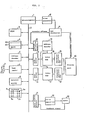
- Fig. 2 is a block diagram illustrating the principal part of an example of the hardware structure of a unit embodying the present invention
- Figs. 3 and 4 are flowcharts showing examples of the software structure of the unit embodying the present invention
- Fig. 5 is a block diagram illustrating an example of the hardware structure of a unit for providing an accentuated display of a specified address portion by changing brightness.
- Fig. 2 is a block diagram illustrating the principal part of an example of the hardware structure of a;:unit embodying the present invention.
- Reference numeral 1 indicates a microcomputer, 2 its bus, 3 a ROM having stored therein a program or the like necessary for the microcomputer 1 to execute predetermined operations, 4 a RAM having a temporary input buffer area 4a, a running information buffer area 4b and so forth, 5 an address decoder, 6 a tape reader, 7 a command tape, 8 an external memory such as a magnetic bubble memory or the like, 9 a keyboard provided with an emphasized display command key 9a, other command keys 9b and a plurality of character input keys 9c, 10 a pulse generator, 11 a CRT controllr, 12 an address switching circuit, 13 an address decoder, 14 and 15 data drivers, 16 a normal color video RAM, 17 an emphasizing color video RAM, 18 and 19 character generator ROMs, 20 a display part such as a CRT or the like, 21 an axis control circuit, 22 a
- NC command program when provided in the form of the command tape 7, is read into the microcomputer 1 via the tape reader 6, and when provided in a state in which it is stored in the external memory 8, it is read out directly therefrom.
- the NC command program is stored in the external memory 8.
- the microcomputer 1 reads out the NC command program from the external memory 8 block by block and interprets it and, in accordance with running information produced on the basis of the result of interpretation, controls the axis control circuit 21, controlling the rotation of the motor 22 via the servo amplifier 22.
- Fig. 3 is a flowchart showing an example of the software structure of the unit embodying the present invention. A description will be given, with reference to Fig. 3, of the specified address accentuating display function of the unit embodying the present invention.
- the microcomputer 1 reads out its input key code (Sl) and discriminates whether it is a character code or not (S2). In this case, since the input key code is a character code, the microcomputer 1 loads the input character in the temporary input buffer area 4a of the RAM 4 (S3) and, at the same time, writes the input character, for instance, via the data driver 14 into the normal color video RAM 16 at a predetermined position, for example, at a position which corresponds to the lower end portion of a display screen ( S 4).
- the contents of the video RAMs 16 and 17 are being cyclically applied, by scanning addresses from the CRT controller 11, to the display part 20 via the character generator ROMs 18 and 19, so that the contents of the temporary input buffer area 4a are displayed on the display screen of the display part 20.
- This is intended for facilitating recognition.
- the output of the video RAM 16 is converted into a video signal of an ordianry color, for example, green
- the output of the video RAM 17 is converted into a video signal of an emphasized color, for instance, red. Accordingly, the character written into the video RAM 16 is displayed in green and the character written into the video RAM 17 in red, and a character written in the both video RAMs at the same address is displayed in yellow.
- the microcomputer 1 inputs its key code (Sl) and performs the discriminations of steps S2 and S5, discriminating that the input key is the emphasized display command key 9a.
- S6 processing corresponding to the input keys is carried out.
- step S5 When it is discriminated in step S5 that the input key is the emphasized display command key, it is then checked whether the content of the temporary input buffer area 4a is one character or not and whether the stored content is an address character or not (S7, S8), and when it is neither one character nor an address character, an error display is produced (S9). This takes into account that an address in the NC command program is usually one alphabetic character and that not all the characters can be addresses.
- an emphasized display of the specified address is produced (S10), after which the content of the temporary input buffer area 4a and the display are cleared (S11).
- Fig. 4 is a flowchart showing an example of software for implementing the emphasized display processing function.
- the microcomputer 1 makes display color information set in the RAM 4 ordinary-color and, at the same time, sets a pointer, which indicates a display position similarly set in the RAM 4, to a value corresponding to the left upper corner of the display screen, for instance (S20).
- the microcomputer reads, for example, the first character of the NC command program stored in the external memory 8 (S21) and checks whether the character is an address character or not, and whether it is an address to be displayed or not (S22, S23).
- display color information is set to an emphasizing color (S24) and the input character is written into an area of the emphasizing color video RAM 17 indicated by a pointer ( S 25), after which the value of the pointer is incremented by one (S26).
- step S25 the display color information is set to an ordinary color (S27).
- the means for displaying the specified address portion in vivid contrast to the other portions it is also possible to use, other than the method of providing the displays in different colors, a method of increasing the brightness of the display of the specified address portion as compared with that of the ether portions.
- Fig. 5 illustrates an example of the hardware structure of a unit which provides an emphasized display of the specified address portion by increasing its brightness.
- Reference numeral 50 indicates a video RAM, 51 a bus controller, 52 a CRT controller, 53 a latch circuit, 54 a character generator ROM, 55 a shift register, 56 a flip-flop, 57 a DA converter, 58 a brightness modulating amplifier and 59 a.driver.
- character data is represented by, for instance, one byte, for example, seven lower-order seven bits being a code representing the kind of the character (for example, an ASCii code) and the most significant bit being data representing brightness.
- a microcomputer, not shown writes such a character code into the video RAM 50.
- the display is produced in the following manner:
- the output of the flip-flop 56 which is supplied with the brightness data latched in the latch circuit 53, is converted by the DA converter into an analog quantity, obtaining a voltage corresponding to the brightness of the character.
- the amplifier 58 has its gain controlled by the voltage, so that the dot data, the amplitude of which varies with the brightness, is provided via the driver 59 to a video signal output terminal. Accordingly, brightness modulation can be effected character by character. Then, by performing brightness change control in place of the color change control in the flowchart of Fig. 4, the brightness of only the specified address portion can be increased.
- the flip-flop 56 in Fig. 5 is provided for delaying the brightness data for one clock in accordance with a delay of one clock which occurs in the time interval between the latching of the character data and the loading of the character pattern into the shift register 55.
- the brightness data has only one bit, but, for instance, by forming one character by 16 bits and by assigning a plurality of bits to the brightness data, a multilevel brightness modulation is also possible.
- move commands for the X- and the Y-axis are absolute commands and a move command for the Z-axis is an incremental command, but, for example, even if the Z-axis is note, the amount of movement in the Z-axis cannot be known accurately unless it is known whether the command therefor is before or behind the command G91.
- the present invention however, such a problem will not arise, as described previously.
Landscapes
- Physics & Mathematics (AREA)
- Engineering & Computer Science (AREA)
- Geometry (AREA)
- Human Computer Interaction (AREA)
- Manufacturing & Machinery (AREA)
- General Physics & Mathematics (AREA)
- Automation & Control Theory (AREA)
- Numerical Control (AREA)
- Testing And Monitoring For Control Systems (AREA)
Applications Claiming Priority (2)
| Application Number | Priority Date | Filing Date | Title |
|---|---|---|---|
| JP58061091A JPH0619659B2 (ja) | 1983-04-07 | 1983-04-07 | Nc指令プログラムの特定アドレス強調表示装置 |
| JP61091/83 | 1983-04-07 |
Publications (3)
| Publication Number | Publication Date |
|---|---|
| EP0151184A1 true EP0151184A1 (de) | 1985-08-14 |
| EP0151184A4 EP0151184A4 (de) | 1987-06-03 |
| EP0151184B1 EP0151184B1 (de) | 1990-03-14 |
Family
ID=13161060
Family Applications (1)
| Application Number | Title | Priority Date | Filing Date |
|---|---|---|---|
| EP84901414A Expired - Lifetime EP0151184B1 (de) | 1983-04-07 | 1984-04-04 | Vorrichtung zum betonen und anzeigen eines auf einer bestimmten adresseaufgespeicherten programmteiles einer numerischen steuerung |
Country Status (4)
| Country | Link |
|---|---|
| EP (1) | EP0151184B1 (de) |
| JP (1) | JPH0619659B2 (de) |
| DE (1) | DE3481654D1 (de) |
| WO (1) | WO1984003962A1 (de) |
Cited By (1)
| Publication number | Priority date | Publication date | Assignee | Title |
|---|---|---|---|---|
| US8136262B2 (en) * | 2007-06-29 | 2012-03-20 | Airdri Limited | Drier information system |
Families Citing this family (1)
| Publication number | Priority date | Publication date | Assignee | Title |
|---|---|---|---|---|
| WO2015154174A1 (en) | 2014-04-07 | 2015-10-15 | Carboncure Technologies, Inc. | Integrated carbon dioxide capture |
Family Cites Families (6)
| Publication number | Priority date | Publication date | Assignee | Title |
|---|---|---|---|---|
| JPS6051722B2 (ja) * | 1978-08-23 | 1985-11-15 | オムロン株式会社 | シ−ケンスコントロ−ラの命令検索方式 |
| JPS5537250A (en) * | 1978-09-05 | 1980-03-15 | Nissan Motor Co Ltd | Numerical controlled lathe with display device |
| DE2929545A1 (de) * | 1979-07-20 | 1981-01-29 | Heidenhain Gmbh Dr Johannes | Verfahren und schaltungsanordnung zur programmerstellung und/oder programmaenderung bei numerisch gesteuerten maschinen |
| JPS5755407A (en) * | 1980-09-18 | 1982-04-02 | Mitsubishi Electric Corp | Numerical controller |
| JPS57189239A (en) * | 1981-05-15 | 1982-11-20 | Yokogawa Hokushin Electric Corp | Listing system for program list |
| JPS5899803A (ja) * | 1981-12-09 | 1983-06-14 | Mitsubishi Electric Corp | 数値制御装置 |
-
1983
- 1983-04-07 JP JP58061091A patent/JPH0619659B2/ja not_active Expired - Lifetime
-
1984
- 1984-04-04 DE DE8484901414T patent/DE3481654D1/de not_active Expired - Lifetime
- 1984-04-04 EP EP84901414A patent/EP0151184B1/de not_active Expired - Lifetime
- 1984-04-04 WO PCT/JP1984/000165 patent/WO1984003962A1/ja not_active Ceased
Cited By (1)
| Publication number | Priority date | Publication date | Assignee | Title |
|---|---|---|---|---|
| US8136262B2 (en) * | 2007-06-29 | 2012-03-20 | Airdri Limited | Drier information system |
Also Published As
| Publication number | Publication date |
|---|---|
| JPH0619659B2 (ja) | 1994-03-16 |
| JPS59186004A (ja) | 1984-10-22 |
| WO1984003962A1 (fr) | 1984-10-11 |
| DE3481654D1 (de) | 1990-04-19 |
| EP0151184B1 (de) | 1990-03-14 |
| EP0151184A4 (de) | 1987-06-03 |
Similar Documents
| Publication | Publication Date | Title |
|---|---|---|
| US4646077A (en) | Video display controller system with attribute latch | |
| EP0259827A2 (de) | Anzeigegerät | |
| EP0117614A2 (de) | Graphische Anzeigeeinheit für numerisch gesteuerte Maschinen | |
| US4725960A (en) | Method of sizing an image on a graphic display for a numerical controller | |
| EP0151184B1 (de) | Vorrichtung zum betonen und anzeigen eines auf einer bestimmten adresseaufgespeicherten programmteiles einer numerischen steuerung | |
| US5359530A (en) | Animated plotting method in NC apparatus for multi-system lathe | |
| JPH025102A (ja) | Pcラダー図の入力方式 | |
| US5878194A (en) | Method and device for outputting multicolor document | |
| EP0140978A1 (de) | Vorrichtung zum anzeigen eines teils eines auf einer spezifischen adresse gespeicherten numerischen steuerprogramms | |
| JPS61131853A (ja) | 加工機用デイスプレイ方法及び装置 | |
| EP0146631A1 (de) | Dateneintragesystem für numerisch gesteuerte vorrichtung | |
| JP2000258197A (ja) | 環境試験装置及びこれの試験パターンの設定方法 | |
| GB2099667A (en) | Programming system with CRT and display unit | |
| JPS61249109A (ja) | 数値制御装置の対話プログラム作成方式 | |
| JP3176080B2 (ja) | 文書処理方法及び装置 | |
| JPH0640254B2 (ja) | カラ−表示装置 | |
| JPH05341832A (ja) | Cncの図形干渉チェック方式 | |
| JP2504551B2 (ja) | 入力デ―タのエラ―検出処理方式 | |
| US5452202A (en) | NC data creation method | |
| JPS61187011A (ja) | 数値制御装置のグラフィック表示装置 | |
| JPH0659849A (ja) | ペイントメニュー制御方式 | |
| JP2771047B2 (ja) | 文書処理方法及び装置 | |
| JPS63261388A (ja) | デ−タ処理装置の文字デ−タ出力方式 | |
| JPS61237117A (ja) | 情報処理装置 | |
| JPS61237115A (ja) | 情報処理装置 |
Legal Events
| Date | Code | Title | Description |
|---|---|---|---|
| PUAI | Public reference made under article 153(3) epc to a published international application that has entered the european phase |
Free format text: ORIGINAL CODE: 0009012 |
|
| 17P | Request for examination filed |
Effective date: 19841212 |
|
| AK | Designated contracting states |
Kind code of ref document: A1 Designated state(s): DE FR GB Designated state(s): DE FR GB |
|
| A4 | Supplementary search report drawn up and despatched |
Effective date: 19870603 |
|
| 17Q | First examination report despatched |
Effective date: 19881024 |
|
| GRAA | (expected) grant |
Free format text: ORIGINAL CODE: 0009210 |
|
| AK | Designated contracting states |
Kind code of ref document: B1 Designated state(s): DE FR GB |
|
| REF | Corresponds to: |
Ref document number: 3481654 Country of ref document: DE Date of ref document: 19900419 |
|
| ET | Fr: translation filed | ||
| PLBE | No opposition filed within time limit |
Free format text: ORIGINAL CODE: 0009261 |
|
| STAA | Information on the status of an ep patent application or granted ep patent |
Free format text: STATUS: NO OPPOSITION FILED WITHIN TIME LIMIT |
|
| 26N | No opposition filed | ||
| PGFP | Annual fee paid to national office [announced via postgrant information from national office to epo] |
Ref country code: FR Payment date: 19910314 Year of fee payment: 8 |
|
| PG25 | Lapsed in a contracting state [announced via postgrant information from national office to epo] |
Ref country code: FR Effective date: 19921230 |
|
| REG | Reference to a national code |
Ref country code: FR Ref legal event code: ST |
|
| PGFP | Annual fee paid to national office [announced via postgrant information from national office to epo] |
Ref country code: GB Payment date: 19930324 Year of fee payment: 10 |
|
| PGFP | Annual fee paid to national office [announced via postgrant information from national office to epo] |
Ref country code: DE Payment date: 19930421 Year of fee payment: 10 |
|
| PG25 | Lapsed in a contracting state [announced via postgrant information from national office to epo] |
Ref country code: GB Effective date: 19940404 |
|
| GBPC | Gb: european patent ceased through non-payment of renewal fee |
Effective date: 19940404 |
|
| PG25 | Lapsed in a contracting state [announced via postgrant information from national office to epo] |
Ref country code: DE Effective date: 19950103 |