EP0153761A2 - Imprimante pour balance électronique - Google Patents
Imprimante pour balance électronique Download PDFInfo
- Publication number
- EP0153761A2 EP0153761A2 EP85102350A EP85102350A EP0153761A2 EP 0153761 A2 EP0153761 A2 EP 0153761A2 EP 85102350 A EP85102350 A EP 85102350A EP 85102350 A EP85102350 A EP 85102350A EP 0153761 A2 EP0153761 A2 EP 0153761A2
- Authority
- EP
- European Patent Office
- Prior art keywords
- cassette
- label
- sheet
- printer
- receipt
- Prior art date
- Legal status (The legal status is an assumption and is not a legal conclusion. Google has not performed a legal analysis and makes no representation as to the accuracy of the status listed.)
- Granted
Links
Images







Classifications
-
- G—PHYSICS
- G01—MEASURING; TESTING
- G01G—WEIGHING
- G01G23/00—Auxiliary devices for weighing apparatus
- G01G23/18—Indicating devices, e.g. for remote indication; Recording devices; Scales, e.g. graduated
- G01G23/38—Recording and/or coding devices specially adapted for weighing apparatus
- G01G23/42—Recording and/or coding devices specially adapted for weighing apparatus electrically operated
-
- G—PHYSICS
- G01—MEASURING; TESTING
- G01G—WEIGHING
- G01G19/00—Weighing apparatus or methods adapted for special purposes not provided for in the preceding groups
- G01G19/40—Weighing apparatus or methods adapted for special purposes not provided for in the preceding groups with provisions for indicating, recording, or computing price or other quantities dependent on the weight
- G01G19/413—Weighing apparatus or methods adapted for special purposes not provided for in the preceding groups with provisions for indicating, recording, or computing price or other quantities dependent on the weight using electromechanical or electronic computing means
- G01G19/414—Weighing apparatus or methods adapted for special purposes not provided for in the preceding groups with provisions for indicating, recording, or computing price or other quantities dependent on the weight using electromechanical or electronic computing means using electronic computing means only
- G01G19/415—Weighing apparatus or methods adapted for special purposes not provided for in the preceding groups with provisions for indicating, recording, or computing price or other quantities dependent on the weight using electromechanical or electronic computing means using electronic computing means only combined with recording means
-
- G—PHYSICS
- G06—COMPUTING OR CALCULATING; COUNTING
- G06K—GRAPHICAL DATA READING; PRESENTATION OF DATA; RECORD CARRIERS; HANDLING RECORD CARRIERS
- G06K13/00—Conveying record carriers from one station to another, e.g. from stack to punching mechanism
- G06K13/02—Conveying record carriers from one station to another, e.g. from stack to punching mechanism the record carrier having longitudinal dimension comparable with transverse dimension, e.g. punched card
- G06K13/06—Guiding cards; Checking correct operation of card-conveying mechanisms
- G06K13/067—Checking presence, absence, correct position, or moving status of cards
-
- G—PHYSICS
- G06—COMPUTING OR CALCULATING; COUNTING
- G06K—GRAPHICAL DATA READING; PRESENTATION OF DATA; RECORD CARRIERS; HANDLING RECORD CARRIERS
- G06K15/00—Arrangements for producing a permanent visual presentation of the output data, e.g. computer output printers
- G06K15/02—Arrangements for producing a permanent visual presentation of the output data, e.g. computer output printers using printers
- G06K15/16—Means for paper feeding or form feeding
Definitions
- This invention relates to an electronic scale printer, and more particularly a printer in which the printer is connected electrically to an electronic scale used in a department store or supermarket etc. and the desired data are printed in a printing sheet and issued under an instruction from the electronic scale.
- the unit has been applied for direct face-to-face selling between the customer and the store personnel and it sometimes shows one case that the receipt should be issued and the other case that the label should be issued in accordance with the object of use of the unit.
- the conventional type of the printer may be classified into two label printer and receipt printer for use in printing the desired printing mode on the desired printing sheet, that is, the weight of the article is weighed by an electronic scale, the price of the article is calculated in reference to the result of weighing and the unit price (price per unit weight), either one of the label or receipt is issued in view of the result of calcualtion.
- the customer should replace the electronic scale itself or printer to cause an inconvinient practice when he desired to replace the receipt printer already used with the label printer as the size of the store was expanded.
- a separate exclusive totalization printer should be connected or the roll of used label sheet should be removed upon completion of the daily work to replace it with the roll of receipt sheet and to print out the accumulated data, resulting in showing a troublesome operation. Resecting of the roll of label sheet upon printing-out of the accumulated data needed an issuing 6f useless labels, resulting in providing an uneconomical proctice.
- the printer Since the printer was quite thin in view of its function and design, it was hard to perform a replacement of a roll of printing sheet upon completion of the roll of the printing sheet. Therefore, if the roll was completely used during meeting with a consumer, the store personnel should keep the consumer waiting for the replacement of the roll.
- a way of displaying in the label to be attached to an item packed is defined under a rule of the Food Sanitation Act or the Food Fair Competition Rule etc. and the character of item name to be printed on the label is defined more than the desired size.
- the character of item name to be printed on the receipt (usually Japanese KANA character) is quite small in a usual ECR (electronic register) due to complicated printing item data or a sheet width of-printing sheet applied.
- ECR electronic register
- the item name character Nl in the lable is substantailly larger than the item name character N2 in the receipt normally used, and therefore it is practically impossible to issue the receipt having characters for label or to issue the label having characters for receipt.
- the conventional type of the printer only one kind of item name was defined in correspondence with one item and thus it was impossible to issue both label and receipt.
- a fundamental arrangement of the printer of the present invention described above is made in an electronic scale printer in which the main body of the printer is electrically connected to the electronic scale, the desired data are printed on the printing sheet under an instruction from the electronic scale and issued, the cassette for storing the printing sheet for label or receipt is made, the main body of the printer is provided with a mounting part where the cassette is removably arranged and also each of the label printing control means and the receipt printing control means is provided as a printing control means, the above-mentioned control means can be selected in response to the kind of printing sheet stored in the installed cassette, and more practical arrangement is constructed such that it may be provided with:
- the arrangement in which the replacement of the label sheet and the receipt sheet is performed under an installation of the cassette as described above has some mechanical and electrical problems to be solved in the sheet sensing means for detecting the position or presence or absence of the label or detecting the presence or absence of the receipt which are not reviewed in the conventional type of the label printer or receipt printer.
- the mechanical and technical problems consist in the structure of the label position sensor.
- a label position sensor 70 having a transparent type photoelectric sensor is applied, said sensor is constructed such that a light emitting element 71 and a light receiving element 72 are stored and arranged at one end of the substantial 3-shaped prism 73, a label sheet L before printing is passed through a groove 74 formed at the other end of said prism 73, thereby either the fron end or rear end of the label L2 is detected and the printing position of the lable is controlled.
- the above-mentioned detector 70 is arranged at the cassette installing part of the main body of the printer of the present invention, if the cassette is slid along the installing part to perform its installation, the presence of the cassette may hinder the installation of the cassette.
- an insertion and arrangement of the detector 70 in the cassette may be theoretically possible under an arrangement of opening at the bottom part of the cassette.
- the above-mentioned label position sensor has a function for detecting the presence or absence of the receipt when the receipt is to be issued.
- the present invention which should accomplish the above-mentioned objects is characterized in that a sensing element composed of a light emitting element and a light receiving element is arranged at the cassette installing part of the main body of the printer in the above-mentioned fundamental or practical constitution, a sensing part through which the printing sheet before printing is passed is arranged
- the sensing part is provided with a reflection means for causing the light from said light emitting element to be crossed with a running passage of the printing sheet at one side thereof and then reflecting the light in such a direction as incidental to the light receiving element.
- the electrical and technical problems found in the sheet sensing means are based upon the fact that the electronic scale printer of the present invention deals with both the label sheet and the receipt sheet and further the position, presence and-absence-of the label and the presence and absence of the receipt are detected by one sheet sensing means.
- Fig.7a illustrates one example of the receipt sheet R in which a thermosensitive sheet having a desired width is wound as a roll
- Fig.7b illustrates a part near terminal end of the label sheet L in which the thermosensitive labels L2, L2 ...are adhered on the base sheet Ll and wound as a roll.
- a sensing slit m having a width of about 2 mm... and at the rear part of the final label L2 is also arranged a terminal end m' having no adhered part thereon.
- the label L2 When the label L2 is to be printed, it is necessary to confirm the position of each of the labels L2.
- the check of the position is usually performed by sensing the thickness of sheet due to the fact that the part of label L2 is overlapped on the base sheet Ll to make a double sheet and the part of the slit m is occupied by the base sheet Ll only.
- the above-mentioned passing-through type photoelectric sensor is applied and the label sheet L is passed between the light emitting element and the light receiving element, resulting in that the amount of passing-through light is decreased at the part of the label L2 and the amount of passing light is increased at the slit m, thus it is possible to judge the position of the label L2. That is, since the output of the light receiving element becomes "Low” level when-the label L2 is sensed and the output becomes "High” level when the slit m and the terminal end m' are detected, it is possible to judge the presence or absence of the label by.assigning "0"/"1" signals to these levels.
- Fig.29 is a view for illustrating the reason for the above case.
- Fig.29a illustrates a condition of either the label sheet L or the receipt sheet R
- Fig.29b illustrates the output of the photoelectric sensor when these sheets L and R pass through said photoelectric sensor
- Figs.29c and 29d illustrate a level of two-value signal got when the slice level (a reference voltage of comparator: hereinafter called as a reference voltage) is defined as El and E2, respectively.
- a reference voltage of comparator hereinafter called as a reference voltage
- the output levels of the photoelectric sensor when the base sheet Ll and the receipt sheet R are passed are substantially coincided to each other (Figs.29a and 29b).
- the label L2 is passed, the value is decreased lower than this level, and when the receipt sheet R is not present, it is increased more than this level. Therefore, the output level of the photoelectric sensor becomes a low (when the label L2 is passed), midium (when the base sheet Ll or the receipt sheet R is passed) and high (when the sheets R and L are not present) levels, respectively.
- the signal becomes "1" signal irrespective of the presence or absence of the receipt sheet R (Fig.29c), and in turn when the reference voltage is set for example to E2 so as to cause the signal level to be changed over to "0"/"1" under the presence or absence of the receipt sheet R, the signal becomes "0" signal irrespective of the presence or absence of the label L2 in case of applying label sheet L (Fig.29d), resulting in that only either the position sensing of label L2 or the presence or absence of the receipt sheet R may be detected.
- the present invention to accomplish the above-mentioned objects is characterized in that under the above-mentioned fundamental arrangement or practical constitution an output level of the sensor is varied in response to a condition whether the sheet installed in the main body of the printer is the label sheet or the receipt sheet or not.
- Another electrical and technical problem found in the sheet sensing means consists in that there are several kinds of label sheets, thickenss and rate of transparency are also versatile, so that the output level of the sheet sensing means (label position sensor) is varied in reference to the kind of label sheet.
- Fig.33 shows a wave-form illustrating this condition, wherein the wave-form shown by a symbol a is aligned in respect to the reference voltage El, and in turn if the label L2 and the base sheet Ll are thin, its level is increased too much as shown by the wave-form b and if they are thick, it is decreased as shown by the wave-form c, so in both cases it is not possible to discriminate the label L2 from the slit m.
- the present invention to accomplish such objects as above has a change-over means for varying the output level of the sensor in a step-wise manner and a comparator for comparing the output signal from this sensor with the reference value under the above-mentioned fundamental arrangement or the practical constitution and has as its object to set the output level of said sensor in reference to the output of said comparator when said outputlevel is varied in sequence.
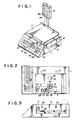
- Fig.l is an outer appearance view for showing an electronit is an outer appearance view for showing scale in which a printer of the present invention is integrally assembled, wherein 1 designates the main body of thetician, 3 designates a cassette installing part and 11 designates a weighing pan to which a weighing sensor (not shown) such as a load cell is connected to form a weighing part 51 (see Fig.23).
- the preset keys 14 are a key for use in calling up preset data such as preset unit price for each of the items, the ten keys 15 are a key for use in inputting various numerical data and the function keys 16 are a key for use in correcting operation.
- the cassette 4 denotes a cassette for storing receipt sheet R or label sheet L shown in Fig.7 and the cassette is removably attached to the cassette installing part 3 of the main body 1 of said printer.
- the receipt cassette for storing the receipt sheet R is designated as 4a
- the label cassette for storing the label sheet L is designated as 4b and they are totally called as a cassette 4.
- the receipt cassette 4a is formed with an opening of sheet issuing port 17 at one corner of a shallow box as shown in Fig.5, and a platen roller 5 for use in printing and feeding the sheet is arranged at the inside of the issuing port 17 and also a cutter 18 for use in cutting the receipt sheet having printing operation completed is arranged near the issuing port 17.
- a set shaft 20 for supporting a roll R' having a receipt sheet R wound therein, and a sensing part 21a and a guide roller Gl are arranged along a transporting direction of the receipt sheet ranging-from the set shaft to the issuing port 17.
- the plate on the upper surface of the cassette 4a is a cap plate 22 arranged to be opened or closed. Upon opening of this cap plate 22, the roll R' is set on the set shaft 20, the receipt sheet R is pulled out and then loaded in such a way as the sheet may pass through the sensing part 21a, guide roller Gl, platen roller 5 and the cutter 18 and finally through the issuing opening 17.
- the sensing part 21a cooperates with a sensing element part S3 arranged at the installing part 3 of the main body 1 of the printer so as to construct the sensor 21 and to detect the presence or absence of the receipt sheet R, and their details will be described in detail later.
- the shaft 5a of the platen roller 5 is projected downward of the cassette 4a and is provided with a gear (not shown) to be engaged with a power transmitting gear 23 of the installing part 3.
- the label cassette 4b is applied for storing a label sheet L in a shallow box as shown in Fig.6, and within the cassette 4b is arranged a label peeling-off dispenser 19 in place of the cutter 18 of the above-mentioned cassette 4a and also there arearranged in it a take-up reel 6 for winding up the base sheet Ll having the label peeled off and an adjusting guide roller G2 capable of being moved along an elongated hole 29 and fixed at any position.
- a sensing part 21a having the same structure as that of the sensing part 21a for the cassette 4a, and the presence or absence of the label L2 and the position of the label are detected by this sensing part 21a and the sensing element part S3 (their details will be described later).
- the guide roller G2 is moved along the elongated hole 29, thereby the distance from'the sensing part 21a to the platen roller 5 can be varied in response to the length of the label.
- the shaft 5a of the platen roller 5 is projected out of the cassette 4b and is provided with a gear (not shown) to be engaged with'the gear 28 for use in transmitting a power at the installing part 3.
- the shaft 6a of the take-up reel 6 is projected out of the cassette 4b and is provided with a rubber wheel (not shown) to be press contacted with a friction wheel 30 of the installing part 3.
- Figs.2 and 3 illustrate an installing part 3 for installing the cassette 4.
- the thermal head 2 is arranged at a position corresponding to the platen roller 5 and arranged such that it may be rotated around the fulcrum shaft 2a by a certain amount.
- the thermal head 2 is of a structure in which it may be pushed against the platen roller 5 with the desired printing pressure under an action of spring (not shown) etc.
- a stepping motor M and the motor shaft Ma is projected out of the upper surface of the installing part 3 and then is provided with a gear 25 and the friction wheel 30.
- the gear 25 is engaged with a gear of the platen roller 5 when the gears 26, 27 and 28 are engaged and the cassette 4b is installed and then the platen roller 5 may be rotated by the desired number of rotation.
- the friction wheel 30 is abutted against the rubber wheel of the cassette 4b to cause the take-up reel 6 to be rotated and to take-up the base sheet.
- the platen roller 5 is driven only with a gear 28.
- the installing part 3 of the main body 1 of the printer is provided with a sensing element part S3 which is oppositely faced against the sensing part 21a of the cassette when the the cassette 4 is installed.
- the sensing element part S3 is composed of a light emitting element 23 and a light receiving element 24, the light emitting element 23 and the light receiving element 24 being composed of a semiconductor element, respectively, and the former being composed of a light emitting diode and the latter being formed of a phototransistor. They are arranged in parallel and buried in the bottom wall and connected to a control unit (not shown) for controlling the driving of the stepping motor M.
- the sensing part 21a of the cassette 4 which constitutes the sensor 21 along with the sensing element part S3 will be described in detail in reference to Figs.8 to 10.
- the sensing part 21a is provided with a pair of raised walls 34 and 35 which are raised from the bottom wall 33 of the cassette 4.
- the raised walls 34 and 35 are bent at an angle 45 ° in a direction crossing with each other, and the label sheet L or the receipt sheet R (for a sake of convenience of description, the label sheet will be described) will pass through between these raised walls 34 and 35.
- the raised wall 35 is connected to the upper end of one of the raised walls 34 and 35, for example, the raised wall 35 is connected a vertical raised guide wall 36 integrally, and the label base sheet Ll is guided by this guide wall 36.
- the reflecting means is composed of a prism having a shape to be fitted in the sensing part 21a.
- the prism 37 is provided with a groove 38 for passing the label sheet L at its intermediate part, its lower end is fitted to the opening hole 39 of the bottom wall 33 of the cassette and is flush with the outer surface of the bottom wall 33.
- the sensing part 21a is operated such that when the cassette 4 is installed in the main body 1 of the printer during its use, one label L2 subsequent to the proceeding label L2 positioned at the printing part (between the platen roller 5 and the thermal head 2) is positioned in the sensing part 21a, a light from the light emitting element 23 is reflected against a reflection means in the sensing part 21a, i.e. a prism 37 and incident to the light receiving element 24 after crossing the passing path of the label L2, an intensity of light incident to the light receiving element 24 is varied in response to the presence or absence of the label L2 , thereby either the front end or rear end of the label L2 is detected and the sensing of the label position is performed.
- a reflection means in the sensing part 21a i.e. a prism 37 and incident to the light receiving element 24 after crossing the passing path of the label L2
- an intensity of light incident to the light receiving element 24 is varied in response to the presence or absence of the label L2 , thereby either the front end or rear
- the sensing sensitivity can be improved by a method wherein the opposed surface of the prism 37 facing to both sides of the groove 38 acting as the passing path of the label L 2 is made narrow. That is, a narrow width of the opposed surfaces may cause a converged part therein to enable the intensity of light to be increased.
- the above-mentioned light reflecting means is not limited to the prism 37 above, but, for example, as shown in Fig.9, it may be constructed such that the inner surfaces of the bent parts 34a and 35a of the raised walls 34 and 35 in the sensing part 21a are of a mirror surface.
- the printing position of the label L2 is modified.
- the number of steps of the stepping motor M for driving the platen roller 5 is varied or the'length of the passing path of the label 1 is elongated or shortened by displacing the guide roller G2 as described above, and so in the present preferred embodiment, the latter means is employed as described above.
- Detailed illustration of the guide roller G2 is given in Fig.10, wherein the guide roller G2 has its flucrum shaft 45 slidably fitted in the elongated hole 29 in the cassette bottom wall 33 and engaged in the bottom wall 3-3 through screw 40 and washer 41.
- the unit is constructed such that the kind of label L2 being used at present can be recognized by detecting the position of the guide roller G2.
- the bottom wall 33 of the installing part 3 of the main body 1 of the printer below the elongated hole 29 is provided with the number of sensing elements corresponding to the kind of label L2, for example, if the length of the label has three kinds, three sensing elements 42, 43 and 44 are arranged. These sensing elements 42, 43 and 44 are applied to detect the screw 40 for the guide roller G2, the sensing element being of a reflection type sensor, a microswitch and a magnetic switch such as hole element etc., and the elements are connected to a display means (not shown) and the result of sensing operation is displayed in the display means.
- the screw 40 for the guide roller G2 is made as a magnet.
- the sensor 21 is divided into the sensing part 21a and the sensing element part S3, the sensing part 21a is arranged in the cassette 4, the sensing element part S3 is arranged at the installing part 3 of the main body 1 of the printer, and when the label sheet L or the receipt sheet R is installed at the cassette 4, the sheet L or R is passed through the sensing part 21a, so that mere installation of the" cassette 4 enables the sheet L or R to be set in the sensor 21. Therefore, the unit may provide an effective attaching or removal of the cassette 4 as well as its replacement and also no projecting member of the cassette 4 may provide such an effect as the installing direction of the cassette is not restricted.
- Sensing means for sensing 'it if the printing sheet loaded in the cassette 4 is of a label sheet or receipt sheet will be described.
- This sensing means is operated such that the sensor S1 is arranged in advance at the installing part 3 of the main body 1 of the printer, the kind of the cassette 4 is defected by the sensor and thereby the sheet is judged if it is the label sheet L or the receipt sheet R. For this reason, the cassette 4a and the cassette 4b are provided with different marks, e.g. openings therein. In the preferred embodiment, a hole 46 is made at the rear surface of the label cassette 4b and the receipt cassette 4a is not provided with any openings (see Figs.6 and 5).
- the above-mentioned sensor Sl is of a reflection type sensor which is installed at the abutting portion 3' of the installing part 3 to detect the presence or absence of the hole 46 when the cassette 4 is installed and judges if the cassette is the label cassette 4b or the receipt cassette 4a by the presence or absence of the hole.
- the printing sheet is a label sheet L and in turn if the cassette 4a is detected, the loading of the receipt sheet R in the main body 1 of the printer is electrically detected.
- the sensor S2 provided in the installing part 3 senses if the cassette 4 is positively installed in the installing part 3 or not (Figs.2 and 3).
- the cassette 4 when the cassette 4 is inserted at the side opening of the installing part 3 and up to the abutting position of the installing part 3, it may be fixed by a leaf spring (not shown).
- the thermal head 2 is abutted against the platen roller 5 and pressed with a desired pressure and at the same time it may be engaged with the driving gear 28 of the platen roller 5 and the driving rubber wheel of the take-up reel 6 is abutted against the friction wheel 30.
- the sensor S2 detects if the cassette 4 is positively installed or not and the sensor Sl recognizes the kind of printing sheet in the cassette 4.
- the kind of the sheet can be detected by the presence or absence of the hole 46, and if there are more than three kinds of printing sheets to be sensed, two holes 46 are made and a combination of the presence or absence of each of the holes may detect the kind of sheet.
- the kind of the printing sheet is defined for each of the combinations of hole:hole, hole:non-hole, non-hole: hole, non-hole:non-hole etc.
- a sliding plate 47 is arranged at the hole 46 of the cassette 4 to open and close the hole 46, resulting in that a compatibility of the cassette can be improved and no trouble is found in storing of the receipt sheet R in the label cassette 4b and in storing of the label sheet L in the receipt receipt cassette 4b.
- the kind of the printing sheet in the cassette 4 sensed in this way is display as shown in Figs.14 and 15 by indicating the kind by an arrow or illuminating it.
- the display is not limited to the display part 12, but it may be arranged at a place where it may easily be seen or it may be indicated by sound.
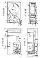
- Figs.l6 to 21 illustrate a system in which the platen roller 5 is driven and the take-up reel 6 is driven by a power from the platen roller 5.
- the installing part 3 has a stepping motor M' below it, a shaft Ma' of the motor M' is projected out of the upper surface of the installing part 3, a gear 8 for use in transmitting a power force is mounted and at the same time a gear 9 is engaged with the gear 8.
- a shaft 9a of the gear 9 is slidably installed in an arcular groove 10 around the motor shaft Ma' and biased in one direction by a spring.(not shown).
- the cassette 4b is constructed such that the shaft 5a of the platen roller 5 is projected out of the cassette, a pulley 48 and a gear 49 are coaxially attached to the shaft 5a and at the same time the shaft 6a of the take-up reel 6 is similarly projected out of the cassette, a pulley 48' is fixed to the shaft 6a, a rubber belt 50 is wound around both pulleys 48 and 48' so as to transmit a power force from the shaft 5a to the shaft 6a.
- the gear 49 is engaged with the gear 9 at the installing part 3 to accept the power force from the stepping motor M'.
- the cassette 4b is slid and installed at the side opening in the installing part 3.
- the gear 9 is moved along the arcular groove 10 while being rotated around the outer circumference of the gear 8, so that the installation of the cassette 4b causes the gear 9 to be engaged with the gear 49. Since the direction of escaping of the gear 9 is opposite to the rotational direction of the motor M ', the rotation of the motor M' causes the gear 9 to be pressed against the gear 49, resulting in that a positive transmitting of power force can be assured.
- the preferred embodiment of the present invention is constructed such that the platen roller 5 is driven, so that the printing can be performed by feeding the printing sheet even in case that the take-up reel is required and also in case that the take-up reel is not required.
- the cassette may be of the same construction, the cost is not expensive and it is pcssible to provide a quite convenient product.
- Fig.22 illustrates a structure in which a driving source is connected to each of the platen roller 5 and the take-up reel 6.
- the stepping motor Ml and the DC motor M2 are mounted in the main body 1 of the printer, and the gears 28' and 30' are rotatably diiven by and attached to the shafts Ml' and M2' of the motors Ml and M2.
- a gear 31 engaging with the gear 28' is mounted on the shaft 5a of the platen roller 5 of the cassette 4b, and a gear 32 engaging with the gear 30' is mounted on the shaft 6a of the take-up reel 6.
- each of the weighing part 51, the main body 1 of the printer, operating part 13 and the display part 12 having the above-mentioned constitution is connected to a bus 56 and CPU 57 through interface circuits 52, 53, 54 and 55.
- ROM read-only-memory
- RAM random-access-memory
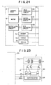
- the main body 1 of the printer is, as shown in Fig.24, composed of the following component elements:
- D/A converter circuit 63 is applied for converting SDO to SD3 of four-bit signals fed from the printer interface Circuit 53 to the analogue signal SA, and is composed of an adder circuit mainly having a calculation amplifier (hereinafter called as OP amp) OP1.
- OP amp calculation amplifier
- To the resistors RO to R3 for adder are applied said signals SDO to SD3 through the voltage followers VFO to VF3.
- the values of resistors RO to R3 are, for example, weighted by 8K, 4K, 2K and 1K ⁇ , correspond to sixteen SD values defined by four bit signals SDO to SD3 and thus the analogue signal SA of sixteen levels can be outputted.
- the resistor Rf is a resistor for use in feeding-back operation
- the resistor Rc is a resistor for accommodation
- the resistor Rp is a resistor for pull-up operation.
- the output level adjusting circuit 62 is composed of the transistor Q1 and an equivalent resistance be-tween the- - collector and emitter of the transistor Ql is varied.
- the collector of the transistor Q1 is connected to the emitter of the light receiving element (phototransistor) of the sensor S3, and this connecting point is connected to the inverted input terminal of the comparator 65.
- the voltage at the inverted input terminal of the comparator 65 i.e.
- the output voltage Vo of the sensor S3 is, as shown in Fig.27, determined by a ratio between an equivalent resistor Ra of the light receiving element 24 and the equivalent resistance Rb between the collector of the transistor Q1 and the ground (this value is a sum of an equivalent resistance value between the collector and the emitter of the transistor Q1 and the resistance value of the resistor Re between the emitter and the ground). That is, if the resistance Rb is constant, light receiving amount of the light receiving element 24 is increased, as the resistance Ra is decreased, the output voltage Vo is increased, and if the light receiving amount of the light receiving element 24 is constant (at this time, the resistance value Ra is constant), the more the resistance Rb, the more the output voltage Vo.
- the light receiving amount is decreased, so that the resistance value Rb is increased to raise up the level of the output voltage Vo, and in turn when the receipt sheet 1 is used, the light receiving amount is increased and so the resistance value Rb is decreased and the level of the output voltage Vo is decreased.
- the label sheet L all the signals SD0 to SD3 are applied as "1'' signal, and the output signal SA of the D/ A convertor circuit 63 is decreased (since the OP amp OP1 forms an inverted adder, the more the values of SDO to SD3, the less the output SA), thereby the resistance value Ro is increased.
- the outputs from the sensors Sl and S2 are inverted by the inverters 56 and 57 to become the signals KS1 and KS2.
- the signals KS1 and KS2 become "1" signal ("High” level) when the light receiving elements of the sensors Sl and S2 accept the light, and in turn become “0” signal when they do not accept the light.
- the cassette 4 is judged if it is a receipt cassette 4a or a label cassette 4b. That is, if it is a receipt cassette 4a, the light receiving elements of the sensors Sl and S2 receive the light, the signals KS1 and KS2 become "1" signal and if it is a label cassette 4b, only the. sensor S1 receives the light, the signal KSl becomes “1” and the signal KS2 becomes "0" signal.
- CPU57 discriminates the cassette 4, and sets all the signals SDO to SD3 to "0" signal when it is a receipt cassette 4a, and sets all the signals SDO to SD3 to "1" signal when it is a label cassette 4b.
- the output of the sensor S3 kept at the level shown in Fig.28b is transferred to the level shown in Fig.28c by the output level adjusting circuit 62 in correspondence with the label sheet 1 and the receipt sheet R shown in Fig.28a, the "High” level of the output voltage Vo of the sensor S3 becomes sufficiently higher than the reference voltage Es and the "Low” level becomes sufficiently lower than the reference voltage Es.
- the signal KS3 becomes "1" signal when the label L2 is detected in case of the label sheet L and becomes "0" signal when the base sheet Ll (i.e.
- the resistance value Rb is increased as the level of the analogue signal SA is decreased, and the level of the signal SA is decreased as the value SDs of the signals SDO to SD3 are increased, so'that these relations are as follows: in turn,
- the value SD is increased to raise the output voltage Vo and in turn when the thin label sheet L is used, the value SD is decreased and the output voltage Vo is decreased and these voltages Vo are oscillated between the values over and below the reference voltage Es (see Fig.32b). If the output voltage Vo is adjusted as above, the output signal KS3 of the comparator 65 becomes "High" level ("1" signal) when a relation of Vo ⁇ Es is found and in turn it becomes “Low” level ("0" signal) when a relation of Vo > Es is found.
- the CPU57 judges that this cassette is a label cassette at first in reference to the signals KS1 and KS2, and then automatically adjusts the value SD of the signals SDO to SD3 in response to the thickness of the label sheet L in such a way as the output voltage Vo of the sensor S3 is oscillated between the values of over and below the reference voltage Es when the abse sheet Ll/label L2 are detected.
- Fig.30 is a view for showing how the level of the output voltage Vo is varied and illustrates each of the cases,'i.e. (i) the sensor S3 has no sheet at its sensing point, (ii) the label L2 is found (iii) the base sheet L1, i.e. either the slit m or the terminal end m' is found, (iv) item completely shielding light, respectively.
- a relation between the output voltage Vo and the reference voltage Es can be defined as Vo ⁇ Es when the label L2 is found, and in turn as Vo > Es when the base sheet L1 is found.
- the value SD equals to 6
- the CPU57 may perform the following process in order to set the value SD as above.
- the level of the output voltage Vo of the sensor S3 is automatically adjusted in response to the thickness of the label sheet L and the level of Vo is adjsuted in such a way as it may show substantially a constant value. That is, in case that the output level adjusting circuit 62 is not present, as shown in Fig.32a, the level of output voltage Vo which is varied in response to the thickness of the label sheet L is changed to the level shown in Fig.32b after adjustment of level, "High" level of the output voltage Vo becomes sufficiently higher than the reference voltage Es and "Low” level becomes sufficiently lower than the value Es. As a result, the signal KS3 is positively changed over to "1"/"0" in response to the presence or absence of the label L2 and a positive sensing can always be performed.
- the level adjustment is performed when the cassette is installed, and the level adjustment may also be performed after the key operation at the operating part, for example, the feed key in the function key is performed. With this arrangement, it is possible to prevent the label from being uselessly applied under a level adjustment for every installation of cassette.
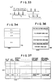
- ROM 58 has areas El to E4 as shown in Fig.34, each of the areas El to E3 has a label printing program, a receipt printing program and a control program stored therein, and the area E4 has various characters (numbers, symbols etc. are contained) and patterns (dot-patterns) stored therein.
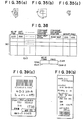
- Figs.35 (a) to (c) illustrate one example of character pattern
- the area E4 has Japanese kana characters (46 characters) of 16 x 8 dots configuration shown in Fig.35(a), numbers (ten characters) of 16 x 8 dots configuration, Japanese kana characters (46 characters) of 16 x 8 dots configuration, Chinese characters (100 characters) of 16 x 16 dots configuration shown in Fig.35(b), Japanese kana characters (46 characters) of 7 x 5 dots configuration shown in Fig.35(c) and numbers (ten characters of 7 x 5 dots configuration and various character patterns.
- the character patterns of 16 x 8 dots and 16 x 16 dots are mainly applied for a label printing operation and the character pattern of 7 x 5 dots configuration is mainly for a receipt printing operation.
- Each of the character patterns is assigned with each of the character codes, and each of the character patterns is read out in reference to the character code.
- RAM 59 is provided with a buffer area EAl PLU (Price Look Up) memory area EA2, data register area EA3 and a total register area EA4 as shown in Fig.36, respectively, and at the same time a working area EA5 is arranged in it.
- EAl PLU Price Look Up
- the printing buffer area EA1 is an area where character pattern to be printed on the label or receipt is written and this area has a capacity corresponding to the printing section of the maximum label.
- PLU memory area EA2 is an area where item number, unit price and appreciation period of each of the products and item name for label printing and item name for receipt printing are set, respectively and area. for storing 100 items is kept.
- the item name to be printed is stored by a character code for each of the characters in the item name column for a label printing and the item name column for a receipt printing, respectively.
- the item name for the label printing for the item number "0152" is "roaf steak” and the item name for the receipt printing is "beef roaf”
- the character codes of Chinese character “ushi (beef)" of 16 x 16 dots, Japanese kana "0", “-” and “ ⁇ ” of 16 x 8 dots are stored in sequence.
- the item name column for the receipt printing are stored in sequence each of the character codes of the Japanese kana '' ⁇ " ", "1", “ “ of 7 x 5 dots.
- the writing in the PLU memory area EA2 is performed by, for example, a host computer or a key operation at the operating part 13.
- the data register area EA3 is an area in which data concerning the product purchased by a consumer and as shown in data of 50 items can be written.
- the total register area EA4 has, as shown in Fig.38, an area EA4-1 and an area EA4-2 where the number of items and total price of the items purchased by a consumer are written.
- the face-to-face selling used herein is a selling process in which sales personnel moves along with the consumer while the consumer moves in a selling spot, the sales personnel utilizes a near-by electronic scale everytime the consumer purchases the product and issues a label indicating a price, adhering the label on the package of the product (at this time, money is not exchanged) and lastly the product is checked at the checkout counter to receive the money.
- the sales personnel sets the label cassette 4b at the installing part 3 of the main body 1 of the printer and then a correct installation of the cassette is confirmed by the display lamp 80 of the display part 12.
- the label cassette 4b sensed by the sensor S1 is written into the working area EA5 of RAM 59 through CPU57 for its cassette data.
- the sales personnel mounts the product on the weighing pan 11 and inputs the item number of the product through the operating part 13.
- the weight data WD corresponding to the weight of the product are outputted from the weighing part 51 (Fig.23).
- CPU57 When the item number is inputted, CPU57 reads out from the PLU data area EA2 of RAM 59 shown in Fig.37 PLU data corresponding to the inputted item number (i.e. unit price, appreciation period, label printing item name and receipt printing item name), then transmits them to the working area EA5 and transfers the weight data WD to the working area EA5. Then, the CPU57 calculates the price of the product in reference to the weight data WD and the unit price data in the working area E A 5 and stores the calculated price data in the working area EA5. Then, the CPU57 outputs the weight data WD, unit price data and price data in the working area EA5 to the display part 12. Thereby, each of the above-mentioned data is displayed in the display part 12 (Fig.l).
- the sales personnel depresses the print key 81 at the operating part 13.
- the sales personnel depresses the plus key 82 at the operating part 13.
- this plus key. 82 is depressed, each of the PLU data, weight data WD and price data in the working area EA5 is transferred to the data register area EA3 (Fig.38) of RAM 59, the data in the area EA4-1 (initially reset) of total register area (Fig.38) are incremented and the price data transferred from the working area EA5.
- the sales personnel demounts the product from the weighing pan 11, puts the next product on the weighing pan 11 and then inputs the item number. Thereby, in the same manner as described above, weight data etc. are displayed at the display part 12.
- the plus key 82 each of the data concerning the second product is stored, the data in the area EA4-1 of the total register area EA4 (in this case "1") are incremented and the price data are added to the data in the area EA4-2. Similar processing will be repeated in sequence.
- the sales personnel performs operation of the plus key 82 for the last item and then depresses the print key 81.
- the sales personnel installs correctly the receipt cassette 4a on the installing part 3 of the main body 1 of the printer, the cassette data are written into the working area EA5 of RAM 59 through CPU57 in the same manner as described above. Then, the sales personnel puts the first item on the weighing pan 11 in a quite same manner as above for the total label printing, inputs the item number, depresses the plus key 82 and then puts the second item on the weighing pan 11, inputs the item number, depresses the plus key 82 and then repeats this process subsequently and finally depresses the plus key 81 upon completion of the operation of depressing plus key for the final item (n-th item).
- the processing performed by the CPU57 corresponding to each of the above operations is the same as that of the total label printing operation described above.
- the printer of the present invention shown in Fig.40 issues the label or receipt
- the feed key -83 in the function keys 16 shown in Fig.l is depressed in advance, and the sensor S3 of the main body 1 of the printer detects the position of the label and detects the presence or absence of the label sheet L and the receipt sheet R in advance.
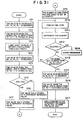
- the CPU57 advances to the step SPl shown in Fig.40 and checks that the above-mentioned data in the working area EA5 are a label cassette 4b and then advances to the step SP2.
- the CPU57 judges if the plus key 82 is depressed or not. If the plus key 82 is not depressed (in case of a single item label), the CPU57 advances to the step SP3, and performs a writing operation for the single item label data into the printing buffer area EAl.
- the unit price data, appreciation period data and the label printing item name data in the working area EA5 are read out, and each of the read data is transformed into the character pattern with the character patterns in the area EA4 of R OM 58 which is written into the printing buffer area EAl under the same arrangement as that of the characters when the label printing is to be performed.
- the CPU57 advances to the step SP4 to perform a writing of total label data into the printing buffer area EAl. That is, the total data in the total register area EA4-2 are transformed into the character pattern and written into the printing buffer area EAl. In this case, the writing of the unit price and the item name are not written into it.
- the CPU57 advances to the step SP5, the content in printing buffer area EA1 is outputted in sequence at the main body 1 of the printer.
- the label printing is performed at the main body 1 of the printer, and for example, the label (single item label in this example) shown in Fig.39a is automatically issued.
- the feeding of the label sheet is performed (step SP6) and the processing is completed upon reaching of the next label to the specified position, i.e. detecting of the slit width m by the sensor S3 (sensing of label position: step SP7).
- step SP8 when the position of the label is not detected, that is, the slit m is not detected even if the desired amount of sheet is fed, the terminal end m' of the label sheet L is detected and no label condition is detected (step SP8).
- step SP10 the presence or absence of the receipt sheet R is detected by the sensor S3, and when no receipt is found (step SP10-YES), the cassette_empty light 84 in the display part 12 is illuminated (step SPll).
- step SP10 when the presence of the receipt sheet is confirmed (SP10-NO), the CPU advances to the step 12, and in the step SP12, each of the data stored in the total register area EA4-1 and EA4-2 is tansformed into the character pattern and then written into the printing buffer area E A l.
- the CPU advances to the step SP13, the content in the printing buffer area EAl is outputted in sequence to the main body 1 of the printer. Thereby, both the total number of items and the total price are printed in the receipt sheet.
- the CPU advances to the step SP14, the unit price data in the n-th line, receipt item name data, weight data, and price data in the data register area EA3 shown in Fig.38 are read out in sequence and transformed into the character pattern and written into the printing buffer area E A l. Then, the CPU advances to the step SP15, and the content of the printing buffer area EAl is outputted in sequence to the main body 1 of the printer. Thereby, the unit price, item name, weight and price of the product of the n-th order are printed on the receipt sheet.
- the CPU advances to the step SP16, it is judged if the printing of all items written into the data register area EA3 is completed or not. If the result of this judgement is "NO”, the CPU returns back to the step SP14, a printing for the item of the (n-l)th order is performed and the above-mentioned process is repeated.
- the CPU advances to the step SP17. In the step SP17, the store name, date etc. are transformed into the character pattern and written into the printing buffer area EA1 and in the step SP18 the content in the printing buffer is outputted at the main body lof the printer and then in the step SP19 the receipt sheet-is fed.
- the CPU advances to the above-mentioned step SPll to illuminate the cassette empty light 84 in the display part 12 and in turn when the presence of the sheet is detected (in the step SP20-NO), the desired amount of sheet is fed (in the step SP21), then the processing operation will be finished.
- the above-mentioned sheet issuing operation is similarly applied to one item or a plurality of items.
- the system in which the total number of items and the total price are printed in advance compared with that of the item data is employed.
- the printing order is opposite to that of the receipt which is issued by a usual ECR, and this is employed in relation with the label printing control operation and it is apparent that this invention is not limited to such arrangement as above.
- the cassette empty light in the display part 12 is also illuminated when the cassette 4 is not installed at the installing part 3, and is not correctly installed even if it is set in it, i.e. no output signal is produced through the sensor S2.
Landscapes
- Physics & Mathematics (AREA)
- Engineering & Computer Science (AREA)
- Theoretical Computer Science (AREA)
- General Physics & Mathematics (AREA)
- Mathematical Physics (AREA)
- General Engineering & Computer Science (AREA)
- Handling Of Sheets (AREA)
- Record Information Processing For Printing (AREA)
Applications Claiming Priority (10)
| Application Number | Priority Date | Filing Date | Title |
|---|---|---|---|
| JP39845/84 | 1984-03-02 | ||
| JP3984584A JPH0239992B2 (ja) | 1984-03-02 | 1984-03-02 | Purinta |
| JP39844/84 | 1984-03-02 | ||
| JP3984484A JPS60185104A (ja) | 1984-03-02 | 1984-03-02 | ラベル位置検出センサの自動調整装置 |
| JP3389884U JPS60145062U (ja) | 1984-03-08 | 1984-03-08 | ラベルプリンタ |
| JP4487684A JPH0227613B2 (ja) | 1984-03-08 | 1984-03-08 | Denshihakaryopurinta |
| JP44876/84 | 1984-03-08 | ||
| JP33898/84 | 1984-03-08 | ||
| JP278899/84 | 1984-12-28 | ||
| JP27889984A JPS61154956A (ja) | 1984-12-28 | 1984-12-28 | ラベル・レシ−トプリンタ |
Publications (3)
| Publication Number | Publication Date |
|---|---|
| EP0153761A2 true EP0153761A2 (fr) | 1985-09-04 |
| EP0153761A3 EP0153761A3 (en) | 1986-04-30 |
| EP0153761B1 EP0153761B1 (fr) | 1989-09-06 |
Family
ID=27521566
Family Applications (1)
| Application Number | Title | Priority Date | Filing Date |
|---|---|---|---|
| EP85102350A Expired EP0153761B1 (fr) | 1984-03-02 | 1985-03-01 | Imprimante pour balance électronique |
Country Status (5)
| Country | Link |
|---|---|
| US (2) | US4598780A (fr) |
| EP (1) | EP0153761B1 (fr) |
| DE (1) | DE3572881D1 (fr) |
| HK (1) | HK47294A (fr) |
| SG (1) | SG85591G (fr) |
Cited By (6)
| Publication number | Priority date | Publication date | Assignee | Title |
|---|---|---|---|---|
| GB2204834A (en) * | 1987-05-14 | 1988-11-23 | Portals Eng Ltd | Improvements in or relating to thermal label printers |
| EP0225121A3 (fr) * | 1985-11-21 | 1989-08-23 | Tokyo Electric Co., Ltd. | Imprimante d'étiquettes |
| FR2641495A1 (fr) * | 1989-01-11 | 1990-07-13 | Monarch Marking Systems Inc | Appareil d'impression et imprimante |
| FR2647056A1 (fr) * | 1989-01-11 | 1990-11-23 | Monarch Marking Systems Inc | Appareil d'impression d'etiquettes |
| EP0684141A3 (fr) * | 1994-05-24 | 1996-06-05 | Canon Aptex Inc | Dispositif d'impression, sa méthode d'impression et unités d'alimentation de feuilles l'utilisant. |
| EP2275270A1 (fr) * | 2009-07-14 | 2011-01-19 | Illinois Tool Works Inc. | Imprimante d'étiquette |
Families Citing this family (64)
| Publication number | Priority date | Publication date | Assignee | Title |
|---|---|---|---|---|
| NZ215998A (en) * | 1985-05-02 | 1989-10-27 | Ishida Scale Mfg Co Ltd | Electronic scales store merchandise data transmitted from central data base |
| JPS61272176A (ja) * | 1985-05-28 | 1986-12-02 | Tokyo Electric Co Ltd | ラベルプリンタ |
| US4872119A (en) * | 1986-04-28 | 1989-10-03 | Teraoka Seiko Co., Ltd. | Electronic postal scale for computing a postal charge |
| JPS62274377A (ja) * | 1986-05-22 | 1987-11-28 | Tokyo Electric Co Ltd | ラベルプリンタ |
| GB2191151B (en) * | 1986-06-03 | 1990-09-19 | Seiko Epson Corp | Printing mechanism for use in a printer |
| US4944827A (en) * | 1986-07-08 | 1990-07-31 | Pitney Bowes Inc. | Label printing system for a computer output line printer |
| EP0276869B1 (fr) * | 1987-01-30 | 1991-06-26 | Teraoka Seiko Co., Ltd. | Dispositif d'impression d'étiquettes |
| US4920882A (en) * | 1987-09-03 | 1990-05-01 | W. H. Brady Co. | Electronic labeler with printhead and web sensor combined for concurrent travel, and assemblies of identification devices therefor |
| US4844629A (en) * | 1987-09-03 | 1989-07-04 | W. H. Brady Co. | Electronic labeler with printhead and web sensor combined for concurrent travel, and assemblies of identification devices therefor |
| DE3880961T2 (de) * | 1987-11-06 | 1993-09-09 | Victor Company Of Japan | Kassette fuer druckeranordnung. |
| US5078523A (en) * | 1988-03-04 | 1992-01-07 | Varitronic Systems, Inc. | Tape cassette with identifying circuit element for printing machine |
| US5366307A (en) * | 1988-10-17 | 1994-11-22 | Mcgourty Thomas K | Printing control system and method for scalably controlling print energy and cycle time |
| US5085529A (en) * | 1988-10-17 | 1992-02-04 | Insignia Systems, Inc. | Thermal printing system with encoded sheet set |
| US5089897A (en) * | 1990-02-08 | 1992-02-18 | Smith Corona Corporation | Facsimile paper supply cartridge system |
| US5057930A (en) * | 1990-02-08 | 1991-10-15 | Smith Corona Corporation | Plain paper cartridge for facsimile machine |
| US5060076A (en) * | 1990-02-08 | 1991-10-22 | Smith Corona Corporation | Thermal paper cartridge for facsimile machine |
| GB2252633B (en) * | 1991-01-30 | 1994-06-22 | Herbert & Sons Ltd | Packaging printing apparatus for retailing |
| US7214891B1 (en) * | 1992-05-01 | 2007-05-08 | Ishida Co., Ltd. | Method and apparatus for printing merchandising information |
| JP3296621B2 (ja) * | 1992-05-01 | 2002-07-02 | 株式会社イシダ | 販売促進情報の印刷方法、その装置およびラベル |
| US5318370A (en) * | 1992-11-17 | 1994-06-07 | Varitronic Systems, Inc. | Cartridge with data memory system and method regarding same |
| USD366001S (en) | 1994-04-22 | 1996-01-09 | Tokyo Electric Co. | Electronic scale with printer |
| JP2959961B2 (ja) * | 1994-06-28 | 1999-10-06 | 東芝テック株式会社 | プリンタ |
| US5507583A (en) * | 1994-12-22 | 1996-04-16 | Premark Feg Corporation | Label printer having a position sensor |
| US5634730A (en) * | 1995-11-06 | 1997-06-03 | Bobry; Howard H. | Hand-held electronic printer |
| US7044589B2 (en) * | 1997-07-12 | 2006-05-16 | Silverbrook Res Pty Ltd | Printing cartridge with barcode identification |
| USD420608S (en) * | 1999-01-20 | 2000-02-15 | Wu-Hsiung Lee | Electronic weight scale |
| US6194671B1 (en) * | 1999-05-03 | 2001-02-27 | Vaghi Family Intellectual Properties, Llc | Electronic scale |
| US7026556B1 (en) * | 2000-09-15 | 2006-04-11 | Premark Feg L.L.C. | Method and system for controlling messages printed by an in store label printer and related label structure |
| EP1284475A3 (fr) * | 2001-08-17 | 2005-07-27 | Premark FEG L.L.C. | Système de pesage avec affichage pour client-fidèle et méthodes correspondantes |
| EP1359527A3 (fr) * | 2002-04-29 | 2004-06-16 | Premark FEG L.L.C. | Balance de produits alimentaires et méthode pour fournir en magasin aux clients des étiquettes de promotion |
| US20070043621A1 (en) * | 2002-04-29 | 2007-02-22 | Collins Harry W | Food product scale system and method for providing in-store incentives to customers |
| JP4449310B2 (ja) * | 2003-02-27 | 2010-04-14 | 株式会社寺岡精工 | 計量印字装置 |
| USD497560S1 (en) | 2003-02-28 | 2004-10-26 | Pelstar, L.L.C. | Digital rate calculating postage scale |
| WO2004079309A1 (fr) * | 2003-02-28 | 2004-09-16 | Pelstar, L.L.C. | Balance numerique telechargeable de calcul de tarifs |
| USD490735S1 (en) | 2003-02-28 | 2004-06-01 | Pelstar, L.L.C. | Keypad for a digital rate calculating postage scale |
| JP4023354B2 (ja) * | 2003-03-31 | 2007-12-19 | ブラザー工業株式会社 | テープ印刷装置及びプログラム |
| US20040267621A1 (en) * | 2003-06-27 | 2004-12-30 | Schuller Robert J. | Food product scale-based incentive system |
| US20050022686A1 (en) * | 2003-07-28 | 2005-02-03 | Dreampatch, Llc | Apparatus, method, and computer program product for animation pad transfer |
| US8521583B2 (en) | 2003-12-26 | 2013-08-27 | Valassis In-Store Solutions, Inc. | Computerized management system for multi-chain promotions, and related audit system |
| US7597254B2 (en) * | 2004-08-20 | 2009-10-06 | Premark Feg L.L.C. | Scale with automatic identification of specials and other price and product changes |
| US20070005379A1 (en) * | 2005-06-29 | 2007-01-04 | Santos Juan-Castellanos | Scale with auto identification of frequently weighed items |
| US7488003B2 (en) * | 2006-03-30 | 2009-02-10 | Premark Feg L.L.C. | Label supply, label handling method and label printing apparatus |
| DE102008006401A1 (de) | 2008-01-28 | 2009-07-30 | Benteler Automobiltechnik Gmbh | Verfahren zur Herstellung eines Abgasschalldämpfers und Abgasschalldämpfer |
| US8304668B2 (en) * | 2009-01-22 | 2012-11-06 | Premark Feg L.L.C. | Scale with kiosk ordering interface system and method |
| US20100200166A1 (en) * | 2009-02-10 | 2010-08-12 | Toshiba Tec Kabushiki Kaisha | Label printer |
| US8432567B2 (en) * | 2009-06-26 | 2013-04-30 | Premark Feg L.L.C. | Printer and scale for handling RFID labels |
| GB2482310B (en) * | 2010-07-28 | 2013-04-10 | Illinois Tool Works | Printer device |
| JP5687924B2 (ja) * | 2011-02-25 | 2015-03-25 | 株式会社イシダ | 計量印字装置 |
| JP5453362B2 (ja) * | 2011-09-05 | 2014-03-26 | 東芝テック株式会社 | 画像形成装置及び画像形成方法 |
| CN108760006A (zh) * | 2018-04-08 | 2018-11-06 | 广州市海升信息科技有限责任公司 | 一种多功能电子秤 |
| CN109724682B (zh) * | 2018-12-11 | 2020-08-28 | 比尔信息技术(北京)有限公司 | 一种超市称重用的智能标签打印电子称 |
| CN111554057A (zh) * | 2019-02-12 | 2020-08-18 | 株式会社石田 | 计量机 |
| JP7395911B2 (ja) | 2019-09-30 | 2023-12-12 | ブラザー工業株式会社 | 印刷用カセット及び印刷装置 |
| JP7395912B2 (ja) | 2019-09-30 | 2023-12-12 | ブラザー工業株式会社 | 印刷用カセット及び印刷装置 |
| JP7322640B2 (ja) | 2019-09-30 | 2023-08-08 | ブラザー工業株式会社 | 印刷用カセット |
| JP7347077B2 (ja) | 2019-09-30 | 2023-09-20 | ブラザー工業株式会社 | 印刷用カセット |
| JP7327059B2 (ja) | 2019-09-30 | 2023-08-16 | ブラザー工業株式会社 | 印刷装置及び印刷用カセット |
| JP7306197B2 (ja) | 2019-09-30 | 2023-07-11 | ブラザー工業株式会社 | 印刷装置及び印刷用カセット |
| JP7322638B2 (ja) | 2019-09-30 | 2023-08-08 | ブラザー工業株式会社 | 印刷装置及び印刷用カセット |
| JP7625815B2 (ja) | 2020-09-30 | 2025-02-04 | ブラザー工業株式会社 | 補助テープカセット及び印刷用テープカセット |
| JP7604825B2 (ja) | 2020-09-30 | 2024-12-24 | ブラザー工業株式会社 | 印刷用カセット及び印刷装置 |
| JP7651831B2 (ja) | 2020-09-30 | 2025-03-27 | ブラザー工業株式会社 | 補助テープカセット |
| JP7589480B2 (ja) | 2020-09-30 | 2024-11-26 | ブラザー工業株式会社 | 補助テープカセット |
| JP7593152B2 (ja) | 2021-01-29 | 2024-12-03 | ブラザー工業株式会社 | 補助テープカセット、印刷用テープカセット及び印刷用カセット |
Family Cites Families (18)
| Publication number | Priority date | Publication date | Assignee | Title |
|---|---|---|---|---|
| SE364584B (fr) * | 1970-04-13 | 1974-02-25 | Canon Kk | |
| US3717881A (en) * | 1971-02-01 | 1973-02-20 | Esterline Corp | Strip chart drive for recorder |
| US4027590A (en) * | 1973-07-09 | 1977-06-07 | Avery International Corporation | Label, ticket and tag printing machine with interchangeable tape supply and feeder magazines |
| CA1062804A (fr) * | 1974-07-12 | 1979-09-18 | International Business Machines Corporation | Detecteur pour documents |
| US3906240A (en) * | 1974-09-27 | 1975-09-16 | Burroughs Corp | Folding photo-electric detecting device |
| US4101366A (en) * | 1975-09-04 | 1978-07-18 | Teraoka Seikosho Co., Ltd. | Electronic digital display scale with label printer |
| GB1503196A (en) * | 1976-01-28 | 1978-03-08 | Avery W Ltd | Printer control circuitry |
| US4158205A (en) * | 1978-03-29 | 1979-06-12 | Honeywell Inc. | Record spool holder |
| US4254409A (en) * | 1978-12-15 | 1981-03-03 | Quality Micro Systems, Inc. | Control system for full line variable height and width character and symbol printing |
| AU525057B2 (en) * | 1979-03-27 | 1982-10-14 | Kubota Ltd. | Label printing computing scale |
| US4440248A (en) * | 1980-02-09 | 1984-04-03 | Teraoka Seikosho Co., Ltd. | Bar code printer |
| JPS6017717B2 (ja) * | 1980-03-17 | 1985-05-04 | キヤノン株式会社 | 印字装置 |
| JPS5940632B2 (ja) * | 1980-06-20 | 1984-10-01 | 東芝テック株式会社 | ラベル印字装置 |
| AU529285B2 (en) * | 1980-11-21 | 1983-06-02 | Tokyo Electric Co. Ltd. | Label issuing apparatus |
| US4351403A (en) * | 1981-03-09 | 1982-09-28 | W. & T. Avery Limited | Weighing scales incorporating printers |
| JPS58175671A (ja) * | 1982-04-07 | 1983-10-14 | Tokyo Electric Co Ltd | ラベルプリンタ |
| JPS5942985A (ja) * | 1982-09-06 | 1984-03-09 | Sato :Kk | プリンタ−におけるマ−ク検知装置 |
| JPS5990181A (ja) * | 1982-11-15 | 1984-05-24 | Hitachi Ltd | プリンタ制御装置 |
-
1985
- 1985-02-26 US US06/705,533 patent/US4598780A/en not_active Expired - Lifetime
- 1985-03-01 EP EP85102350A patent/EP0153761B1/fr not_active Expired
- 1985-03-01 DE DE8585102350T patent/DE3572881D1/de not_active Expired
-
1986
- 1986-04-16 US US06/852,642 patent/US4700791A/en not_active Expired - Lifetime
-
1991
- 1991-10-14 SG SG855/91A patent/SG85591G/en unknown
-
1994
- 1994-05-12 HK HK47294A patent/HK47294A/en not_active IP Right Cessation
Non-Patent Citations (1)
| Title |
|---|
| None |
Cited By (12)
| Publication number | Priority date | Publication date | Assignee | Title |
|---|---|---|---|---|
| EP0225121A3 (fr) * | 1985-11-21 | 1989-08-23 | Tokyo Electric Co., Ltd. | Imprimante d'étiquettes |
| GB2204834A (en) * | 1987-05-14 | 1988-11-23 | Portals Eng Ltd | Improvements in or relating to thermal label printers |
| GB2204834B (en) * | 1987-05-14 | 1991-06-19 | Portals Eng Ltd | Improvements in or relating to thermal label printers |
| FR2641495A1 (fr) * | 1989-01-11 | 1990-07-13 | Monarch Marking Systems Inc | Appareil d'impression et imprimante |
| GB2227460A (en) * | 1989-01-11 | 1990-08-01 | Monarch Marking Systems Inc | Label printing apparatus. |
| FR2647056A1 (fr) * | 1989-01-11 | 1990-11-23 | Monarch Marking Systems Inc | Appareil d'impression d'etiquettes |
| FR2647055A1 (fr) * | 1989-01-11 | 1990-11-23 | Monarch Marking Systems Inc | Appareil d'impression d'etiquettes |
| GB2227460B (en) * | 1989-01-11 | 1993-10-06 | Monarch Marking Systems Inc | Printing apparatus |
| EP0684141A3 (fr) * | 1994-05-24 | 1996-06-05 | Canon Aptex Inc | Dispositif d'impression, sa méthode d'impression et unités d'alimentation de feuilles l'utilisant. |
| US5953035A (en) * | 1994-05-24 | 1999-09-14 | Canon Aptex Inc. | Printing apparatus and printing method for use with rolled sheet and cut sheet feeding units |
| EP2275270A1 (fr) * | 2009-07-14 | 2011-01-19 | Illinois Tool Works Inc. | Imprimante d'étiquette |
| US8517618B2 (en) | 2009-07-14 | 2013-08-27 | Illinois Tool Works Inc. | Weighing scale with cassette device that moves print head upon insertion with label printer |
Also Published As
| Publication number | Publication date |
|---|---|
| DE3572881D1 (en) | 1989-10-12 |
| EP0153761B1 (fr) | 1989-09-06 |
| US4598780A (en) | 1986-07-08 |
| HK47294A (en) | 1994-05-20 |
| US4700791A (en) | 1987-10-20 |
| SG85591G (en) | 1991-11-22 |
| EP0153761A3 (en) | 1986-04-30 |
Similar Documents
| Publication | Publication Date | Title |
|---|---|---|
| EP0153761B1 (fr) | Imprimante pour balance électronique | |
| US4276598A (en) | Electronic cash register including means for producing printed validation data | |
| US4229794A (en) | Method and apparatus for supplying a label printer with product information | |
| US4746932A (en) | Thermal label printer having I/O capabilities | |
| US4440248A (en) | Bar code printer | |
| US5859414A (en) | Interactive customer information terminal | |
| JP3731165B2 (ja) | バーコードデータ形式の走査およびラベリング装置ならびに方法 | |
| US4142235A (en) | Electronic cash register | |
| US4765765A (en) | Label printer | |
| EP0568088A2 (fr) | Procédé et dispositif pour imprimer de l'information commerciale | |
| US20030205412A1 (en) | Method and apparatus for printing merchandising information | |
| JPH0796315B2 (ja) | プリンタ | |
| TW592993B (en) | Commodity information printing apparatus and commodity label | |
| KR900000701B1 (ko) | 전자식 금전등록기 | |
| US4936693A (en) | Label printing device | |
| EP3210792A1 (fr) | Imprimante, support d'enregistrement et appareil de traitement de données de vente | |
| JPH0239992B2 (ja) | Purinta | |
| JP3403749B2 (ja) | ラベルプリンタ | |
| JP2020138550A (ja) | プリンタ、記録媒体および販売データ処理装置 | |
| JPH0146316B2 (fr) | ||
| JPS6132996B2 (fr) | ||
| FR2674954A1 (fr) | Machine de pesage et d'etiquetage. | |
| JPH0217593A (ja) | サービスカード発行機 | |
| JPH02102076A (ja) | ラベルプリンターとそのデータ入力方式 | |
| JP2024019769A (ja) | ラベル発行装置 |
Legal Events
| Date | Code | Title | Description |
|---|---|---|---|
| PUAI | Public reference made under article 153(3) epc to a published international application that has entered the european phase |
Free format text: ORIGINAL CODE: 0009012 |
|
| AK | Designated contracting states |
Kind code of ref document: A2 Designated state(s): DE FR GB SE |
|
| PUAL | Search report despatched |
Free format text: ORIGINAL CODE: 0009013 |
|
| AK | Designated contracting states |
Kind code of ref document: A3 Designated state(s): DE FR GB SE |
|
| 17P | Request for examination filed |
Effective date: 19861029 |
|
| 17Q | First examination report despatched |
Effective date: 19881206 |
|
| RIN1 | Information on inventor provided before grant (corrected) |
Inventor name: IWASAKI,YOSHITAKA,C/O TERAOKA SEIKO CO.,LTD. Inventor name: TANABE, YOSHIO C/O TERAOKA SEIKO CO., LTD Inventor name: MORI, KUNIO C/O TERAOKA SEIKO CO., LTD |
|
| GRAA | (expected) grant |
Free format text: ORIGINAL CODE: 0009210 |
|
| AK | Designated contracting states |
Kind code of ref document: B1 Designated state(s): DE FR GB SE |
|
| ET | Fr: translation filed | ||
| REF | Corresponds to: |
Ref document number: 3572881 Country of ref document: DE Date of ref document: 19891012 |
|
| PLBE | No opposition filed within time limit |
Free format text: ORIGINAL CODE: 0009261 |
|
| STAA | Information on the status of an ep patent application or granted ep patent |
Free format text: STATUS: NO OPPOSITION FILED WITHIN TIME LIMIT |
|
| 26N | No opposition filed | ||
| EAL | Se: european patent in force in sweden |
Ref document number: 85102350.7 |
|
| REG | Reference to a national code |
Ref country code: GB Ref legal event code: IF02 |
|
| PGFP | Annual fee paid to national office [announced via postgrant information from national office to epo] |
Ref country code: GB Payment date: 20040224 Year of fee payment: 20 |
|
| PGFP | Annual fee paid to national office [announced via postgrant information from national office to epo] |
Ref country code: FR Payment date: 20040225 Year of fee payment: 20 |
|
| PGFP | Annual fee paid to national office [announced via postgrant information from national office to epo] |
Ref country code: SE Payment date: 20040227 Year of fee payment: 20 |
|
| PGFP | Annual fee paid to national office [announced via postgrant information from national office to epo] |
Ref country code: DE Payment date: 20040322 Year of fee payment: 20 |
|
| PG25 | Lapsed in a contracting state [announced via postgrant information from national office to epo] |
Ref country code: GB Free format text: LAPSE BECAUSE OF EXPIRATION OF PROTECTION Effective date: 20050228 |
|
| REG | Reference to a national code |
Ref country code: GB Ref legal event code: PE20 |
|
| EUG | Se: european patent has lapsed |