EP0156625B1 - Vertikaler magnetischer Aufzeichnungsträger und Verfahren zu seiner Herstellung - Google Patents
Vertikaler magnetischer Aufzeichnungsträger und Verfahren zu seiner Herstellung Download PDFInfo
- Publication number
- EP0156625B1 EP0156625B1 EP85301944A EP85301944A EP0156625B1 EP 0156625 B1 EP0156625 B1 EP 0156625B1 EP 85301944 A EP85301944 A EP 85301944A EP 85301944 A EP85301944 A EP 85301944A EP 0156625 B1 EP0156625 B1 EP 0156625B1
- Authority
- EP
- European Patent Office
- Prior art keywords
- substrate
- magnetic layer
- recording medium
- magnetic recording
- magnetic
- Prior art date
- Legal status (The legal status is an assumption and is not a legal conclusion. Google has not performed a legal analysis and makes no representation as to the accuracy of the status listed.)
- Expired
Links
- 230000005291 magnetic effect Effects 0.000 title claims description 352
- 238000000034 method Methods 0.000 title claims description 59
- 230000008569 process Effects 0.000 title claims description 31
- 238000002360 preparation method Methods 0.000 title claims description 15
- 239000000758 substrate Substances 0.000 claims description 150
- XEEYBQQBJWHFJM-UHFFFAOYSA-N Iron Chemical compound [Fe] XEEYBQQBJWHFJM-UHFFFAOYSA-N 0.000 claims description 108
- 239000007789 gas Substances 0.000 claims description 105
- 229910052742 iron Inorganic materials 0.000 claims description 53
- 238000001771 vacuum deposition Methods 0.000 claims description 50
- 239000010941 cobalt Substances 0.000 claims description 49
- 239000001301 oxygen Substances 0.000 claims description 49
- 229910052760 oxygen Inorganic materials 0.000 claims description 49
- GUTLYIVDDKVIGB-UHFFFAOYSA-N cobalt atom Chemical compound [Co] GUTLYIVDDKVIGB-UHFFFAOYSA-N 0.000 claims description 48
- QVGXLLKOCUKJST-UHFFFAOYSA-N atomic oxygen Chemical compound [O] QVGXLLKOCUKJST-UHFFFAOYSA-N 0.000 claims description 47
- 229910017052 cobalt Inorganic materials 0.000 claims description 44
- IJGRMHOSHXDMSA-UHFFFAOYSA-N Atomic nitrogen Chemical compound N#N IJGRMHOSHXDMSA-UHFFFAOYSA-N 0.000 claims description 42
- 229910052751 metal Inorganic materials 0.000 claims description 25
- 239000002184 metal Substances 0.000 claims description 25
- IVMYJDGYRUAWML-UHFFFAOYSA-N cobalt(II) oxide Inorganic materials [Co]=O IVMYJDGYRUAWML-UHFFFAOYSA-N 0.000 claims description 24
- 230000001050 lubricating effect Effects 0.000 claims description 23
- 229910052757 nitrogen Inorganic materials 0.000 claims description 21
- XKRFYHLGVUSROY-UHFFFAOYSA-N Argon Chemical compound [Ar] XKRFYHLGVUSROY-UHFFFAOYSA-N 0.000 claims description 18
- 239000000203 mixture Substances 0.000 claims description 18
- 230000015572 biosynthetic process Effects 0.000 claims description 14
- 239000004721 Polyphenylene oxide Substances 0.000 claims description 13
- 125000005010 perfluoroalkyl group Chemical group 0.000 claims description 13
- 229920000570 polyether Polymers 0.000 claims description 13
- SZVJSHCCFOBDDC-UHFFFAOYSA-N iron(II,III) oxide Inorganic materials O=[Fe]O[Fe]O[Fe]=O SZVJSHCCFOBDDC-UHFFFAOYSA-N 0.000 claims description 12
- 239000011800 void material Substances 0.000 claims description 11
- 229910052786 argon Inorganic materials 0.000 claims description 9
- 229910044991 metal oxide Inorganic materials 0.000 claims description 9
- 150000004706 metal oxides Chemical class 0.000 claims description 9
- VNWKTOKETHGBQD-UHFFFAOYSA-N methane Chemical compound C VNWKTOKETHGBQD-UHFFFAOYSA-N 0.000 claims description 8
- 238000011144 upstream manufacturing Methods 0.000 claims description 7
- OTMSDBZUPAUEDD-UHFFFAOYSA-N Ethane Chemical compound CC OTMSDBZUPAUEDD-UHFFFAOYSA-N 0.000 claims description 5
- YCKRFDGAMUMZLT-UHFFFAOYSA-N Fluorine atom Chemical compound [F] YCKRFDGAMUMZLT-UHFFFAOYSA-N 0.000 claims description 5
- 239000011737 fluorine Substances 0.000 claims description 5
- 229910052731 fluorine Inorganic materials 0.000 claims description 5
- 239000001307 helium Substances 0.000 claims description 4
- 229910052734 helium Inorganic materials 0.000 claims description 4
- SWQJXJOGLNCZEY-UHFFFAOYSA-N helium atom Chemical compound [He] SWQJXJOGLNCZEY-UHFFFAOYSA-N 0.000 claims description 4
- 229910052754 neon Inorganic materials 0.000 claims description 4
- GKAOGPIIYCISHV-UHFFFAOYSA-N neon atom Chemical compound [Ne] GKAOGPIIYCISHV-UHFFFAOYSA-N 0.000 claims description 4
- 229910052704 radon Inorganic materials 0.000 claims description 4
- SYUHGPGVQRZVTB-UHFFFAOYSA-N radon atom Chemical compound [Rn] SYUHGPGVQRZVTB-UHFFFAOYSA-N 0.000 claims description 4
- 229910052724 xenon Inorganic materials 0.000 claims description 4
- FHNFHKCVQCLJFQ-UHFFFAOYSA-N xenon atom Chemical compound [Xe] FHNFHKCVQCLJFQ-UHFFFAOYSA-N 0.000 claims description 4
- 239000004734 Polyphenylene sulfide Substances 0.000 claims description 3
- 239000004760 aramid Substances 0.000 claims description 3
- 229920003235 aromatic polyamide Polymers 0.000 claims description 3
- 150000002894 organic compounds Chemical class 0.000 claims description 3
- 229920000728 polyester Polymers 0.000 claims description 3
- 229920000069 polyphenylene sulfide Polymers 0.000 claims description 3
- 230000000052 comparative effect Effects 0.000 description 56
- 239000010408 film Substances 0.000 description 55
- 238000010894 electron beam technology Methods 0.000 description 35
- 230000005415 magnetization Effects 0.000 description 28
- -1 oxygen ion Chemical class 0.000 description 22
- 239000000523 sample Substances 0.000 description 22
- 229910001882 dioxygen Inorganic materials 0.000 description 20
- MYMOFIZGZYHOMD-UHFFFAOYSA-N Dioxygen Chemical compound O=O MYMOFIZGZYHOMD-UHFFFAOYSA-N 0.000 description 19
- 230000001965 increasing effect Effects 0.000 description 19
- PXHVJJICTQNCMI-UHFFFAOYSA-N Nickel Chemical compound [Ni] PXHVJJICTQNCMI-UHFFFAOYSA-N 0.000 description 18
- UQSXHKLRYXJYBZ-UHFFFAOYSA-N Iron oxide Chemical compound [Fe]=O UQSXHKLRYXJYBZ-UHFFFAOYSA-N 0.000 description 15
- 238000005299 abrasion Methods 0.000 description 14
- 229920000139 polyethylene terephthalate Polymers 0.000 description 14
- 239000005020 polyethylene terephthalate Substances 0.000 description 14
- 230000000694 effects Effects 0.000 description 12
- 238000009751 slip forming Methods 0.000 description 10
- 229910052759 nickel Inorganic materials 0.000 description 9
- RYGMFSIKBFXOCR-UHFFFAOYSA-N Copper Chemical compound [Cu] RYGMFSIKBFXOCR-UHFFFAOYSA-N 0.000 description 8
- 229910000428 cobalt oxide Inorganic materials 0.000 description 8
- 229910052802 copper Inorganic materials 0.000 description 8
- 239000010949 copper Substances 0.000 description 8
- 238000004544 sputter deposition Methods 0.000 description 8
- 238000001704 evaporation Methods 0.000 description 7
- 230000008020 evaporation Effects 0.000 description 7
- 235000013980 iron oxide Nutrition 0.000 description 7
- 229920002799 BoPET Polymers 0.000 description 6
- 238000007611 bar coating method Methods 0.000 description 6
- 230000005540 biological transmission Effects 0.000 description 6
- 238000001816 cooling Methods 0.000 description 6
- 239000000463 material Substances 0.000 description 6
- 229920000620 organic polymer Polymers 0.000 description 6
- VYZAMTAEIAYCRO-UHFFFAOYSA-N Chromium Chemical compound [Cr] VYZAMTAEIAYCRO-UHFFFAOYSA-N 0.000 description 5
- ZOKXTWBITQBERF-UHFFFAOYSA-N Molybdenum Chemical compound [Mo] ZOKXTWBITQBERF-UHFFFAOYSA-N 0.000 description 5
- 238000004458 analytical method Methods 0.000 description 5
- 229910052804 chromium Inorganic materials 0.000 description 5
- 239000011651 chromium Substances 0.000 description 5
- 238000005260 corrosion Methods 0.000 description 5
- 230000007797 corrosion Effects 0.000 description 5
- 238000010586 diagram Methods 0.000 description 5
- 238000005566 electron beam evaporation Methods 0.000 description 5
- 238000010438 heat treatment Methods 0.000 description 5
- 229910052750 molybdenum Inorganic materials 0.000 description 5
- 239000011733 molybdenum Substances 0.000 description 5
- 230000009471 action Effects 0.000 description 4
- 238000005247 gettering Methods 0.000 description 4
- 239000000314 lubricant Substances 0.000 description 4
- 239000002245 particle Substances 0.000 description 4
- 229920006395 saturated elastomer Polymers 0.000 description 4
- BOSAWIQFTJIYIS-UHFFFAOYSA-N 1,1,1-trichloro-2,2,2-trifluoroethane Chemical compound FC(F)(F)C(Cl)(Cl)Cl BOSAWIQFTJIYIS-UHFFFAOYSA-N 0.000 description 3
- 238000004833 X-ray photoelectron spectroscopy Methods 0.000 description 3
- 229910045601 alloy Inorganic materials 0.000 description 3
- 239000000956 alloy Substances 0.000 description 3
- 125000002843 carboxylic acid group Chemical group 0.000 description 3
- 238000002524 electron diffraction data Methods 0.000 description 3
- 238000007733 ion plating Methods 0.000 description 3
- 238000001755 magnetron sputter deposition Methods 0.000 description 3
- WPBNNNQJVZRUHP-UHFFFAOYSA-L manganese(2+);methyl n-[[2-(methoxycarbonylcarbamothioylamino)phenyl]carbamothioyl]carbamate;n-[2-(sulfidocarbothioylamino)ethyl]carbamodithioate Chemical compound [Mn+2].[S-]C(=S)NCCNC([S-])=S.COC(=O)NC(=S)NC1=CC=CC=C1NC(=S)NC(=O)OC WPBNNNQJVZRUHP-UHFFFAOYSA-L 0.000 description 3
- 238000004519 manufacturing process Methods 0.000 description 3
- 238000005192 partition Methods 0.000 description 3
- 230000035699 permeability Effects 0.000 description 3
- 238000004445 quantitative analysis Methods 0.000 description 3
- 238000000682 scanning probe acoustic microscopy Methods 0.000 description 3
- 238000000992 sputter etching Methods 0.000 description 3
- 239000010409 thin film Substances 0.000 description 3
- 238000007740 vapor deposition Methods 0.000 description 3
- OKTJSMMVPCPJKN-UHFFFAOYSA-N Carbon Chemical compound [C] OKTJSMMVPCPJKN-UHFFFAOYSA-N 0.000 description 2
- 229910001289 Manganese-zinc ferrite Inorganic materials 0.000 description 2
- 239000004698 Polyethylene Substances 0.000 description 2
- 238000001069 Raman spectroscopy Methods 0.000 description 2
- JIYIUPFAJUGHNL-UHFFFAOYSA-N [O--].[O--].[O--].[O--].[O--].[O--].[O--].[O--].[O--].[O--].[O--].[O--].[O--].[O--].[O--].[O--].[O--].[O--].[O--].[O--].[Mn++].[Mn++].[Mn++].[Fe+3].[Fe+3].[Fe+3].[Fe+3].[Fe+3].[Fe+3].[Fe+3].[Fe+3].[Fe+3].[Fe+3].[Zn++].[Zn++] Chemical compound [O--].[O--].[O--].[O--].[O--].[O--].[O--].[O--].[O--].[O--].[O--].[O--].[O--].[O--].[O--].[O--].[O--].[O--].[O--].[O--].[Mn++].[Mn++].[Mn++].[Fe+3].[Fe+3].[Fe+3].[Fe+3].[Fe+3].[Fe+3].[Fe+3].[Fe+3].[Fe+3].[Fe+3].[Zn++].[Zn++] JIYIUPFAJUGHNL-UHFFFAOYSA-N 0.000 description 2
- 230000001133 acceleration Effects 0.000 description 2
- 229910052799 carbon Inorganic materials 0.000 description 2
- 150000001735 carboxylic acids Chemical class 0.000 description 2
- 229920001577 copolymer Polymers 0.000 description 2
- 239000013078 crystal Substances 0.000 description 2
- 230000003247 decreasing effect Effects 0.000 description 2
- 230000002950 deficient Effects 0.000 description 2
- 238000000313 electron-beam-induced deposition Methods 0.000 description 2
- 230000002708 enhancing effect Effects 0.000 description 2
- 238000005530 etching Methods 0.000 description 2
- 230000006698 induction Effects 0.000 description 2
- 238000009776 industrial production Methods 0.000 description 2
- 150000002500 ions Chemical class 0.000 description 2
- 238000004093 laser heating Methods 0.000 description 2
- 238000002156 mixing Methods 0.000 description 2
- 239000002985 plastic film Substances 0.000 description 2
- 229920006255 plastic film Polymers 0.000 description 2
- 229920000573 polyethylene Polymers 0.000 description 2
- 239000000700 radioactive tracer Substances 0.000 description 2
- 230000003746 surface roughness Effects 0.000 description 2
- 238000007738 vacuum evaporation Methods 0.000 description 2
- XLYOFNOQVPJJNP-UHFFFAOYSA-N water Substances O XLYOFNOQVPJJNP-UHFFFAOYSA-N 0.000 description 2
- 238000004804 winding Methods 0.000 description 2
- LNAZSHAWQACDHT-XIYTZBAFSA-N (2r,3r,4s,5r,6s)-4,5-dimethoxy-2-(methoxymethyl)-3-[(2s,3r,4s,5r,6r)-3,4,5-trimethoxy-6-(methoxymethyl)oxan-2-yl]oxy-6-[(2r,3r,4s,5r,6r)-4,5,6-trimethoxy-2-(methoxymethyl)oxan-3-yl]oxyoxane Chemical compound CO[C@@H]1[C@@H](OC)[C@H](OC)[C@@H](COC)O[C@H]1O[C@H]1[C@H](OC)[C@@H](OC)[C@H](O[C@H]2[C@@H]([C@@H](OC)[C@H](OC)O[C@@H]2COC)OC)O[C@@H]1COC LNAZSHAWQACDHT-XIYTZBAFSA-N 0.000 description 1
- LSNNMFCWUKXFEE-UHFFFAOYSA-M Bisulfite Chemical compound OS([O-])=O LSNNMFCWUKXFEE-UHFFFAOYSA-M 0.000 description 1
- 229910020587 CmF2m+1 Inorganic materials 0.000 description 1
- 229910000599 Cr alloy Inorganic materials 0.000 description 1
- IAYPIBMASNFSPL-UHFFFAOYSA-N Ethylene oxide Chemical compound C1CO1 IAYPIBMASNFSPL-UHFFFAOYSA-N 0.000 description 1
- 229910000990 Ni alloy Inorganic materials 0.000 description 1
- 239000004952 Polyamide Substances 0.000 description 1
- 239000004642 Polyimide Substances 0.000 description 1
- 239000004743 Polypropylene Substances 0.000 description 1
- 229920001328 Polyvinylidene chloride Polymers 0.000 description 1
- XUIMIQQOPSSXEZ-UHFFFAOYSA-N Silicon Chemical compound [Si] XUIMIQQOPSSXEZ-UHFFFAOYSA-N 0.000 description 1
- QCWXUUIWCKQGHC-UHFFFAOYSA-N Zirconium Chemical compound [Zr] QCWXUUIWCKQGHC-UHFFFAOYSA-N 0.000 description 1
- SMEGJBVQLJJKKX-HOTMZDKISA-N [(2R,3S,4S,5R,6R)-5-acetyloxy-3,4,6-trihydroxyoxan-2-yl]methyl acetate Chemical compound CC(=O)OC[C@@H]1[C@H]([C@@H]([C@H]([C@@H](O1)O)OC(=O)C)O)O SMEGJBVQLJJKKX-HOTMZDKISA-N 0.000 description 1
- VVTSZOCINPYFDP-UHFFFAOYSA-N [O].[Ar] Chemical compound [O].[Ar] VVTSZOCINPYFDP-UHFFFAOYSA-N 0.000 description 1
- 229940081735 acetylcellulose Drugs 0.000 description 1
- 239000000654 additive Substances 0.000 description 1
- 230000000996 additive effect Effects 0.000 description 1
- 229910052782 aluminium Inorganic materials 0.000 description 1
- XAGFODPZIPBFFR-UHFFFAOYSA-N aluminium Chemical compound [Al] XAGFODPZIPBFFR-UHFFFAOYSA-N 0.000 description 1
- 238000004364 calculation method Methods 0.000 description 1
- 125000000271 carboxylic acid salt group Chemical group 0.000 description 1
- 150000001734 carboxylic acid salts Chemical class 0.000 description 1
- 229920002301 cellulose acetate Polymers 0.000 description 1
- 239000000919 ceramic Substances 0.000 description 1
- 230000008859 change Effects 0.000 description 1
- 238000006243 chemical reaction Methods 0.000 description 1
- 150000001868 cobalt Chemical class 0.000 description 1
- 238000004040 coloring Methods 0.000 description 1
- 239000000470 constituent Substances 0.000 description 1
- 238000005336 cracking Methods 0.000 description 1
- 125000004093 cyano group Chemical group *C#N 0.000 description 1
- 238000000151 deposition Methods 0.000 description 1
- 238000003618 dip coating Methods 0.000 description 1
- 238000002845 discoloration Methods 0.000 description 1
- 238000009826 distribution Methods 0.000 description 1
- 238000001035 drying Methods 0.000 description 1
- 238000010891 electric arc Methods 0.000 description 1
- 239000003792 electrolyte Substances 0.000 description 1
- 239000003822 epoxy resin Substances 0.000 description 1
- 125000001495 ethyl group Chemical group [H]C([H])([H])C([H])([H])* 0.000 description 1
- 230000005294 ferromagnetic effect Effects 0.000 description 1
- 230000004907 flux Effects 0.000 description 1
- 239000011521 glass Substances 0.000 description 1
- LNEPOXFFQSENCJ-UHFFFAOYSA-N haloperidol Chemical compound C1CC(O)(C=2C=CC(Cl)=CC=2)CCN1CCCC(=O)C1=CC=C(F)C=C1 LNEPOXFFQSENCJ-UHFFFAOYSA-N 0.000 description 1
- 229920001519 homopolymer Polymers 0.000 description 1
- 230000006872 improvement Effects 0.000 description 1
- 229910010272 inorganic material Inorganic materials 0.000 description 1
- 239000011147 inorganic material Substances 0.000 description 1
- 238000010884 ion-beam technique Methods 0.000 description 1
- IGHXQFUXKMLEAW-UHFFFAOYSA-N iron(2+) oxygen(2-) Chemical compound [O-2].[Fe+2].[Fe+2].[O-2] IGHXQFUXKMLEAW-UHFFFAOYSA-N 0.000 description 1
- VBMVTYDPPZVILR-UHFFFAOYSA-N iron(2+);oxygen(2-) Chemical class [O-2].[Fe+2] VBMVTYDPPZVILR-UHFFFAOYSA-N 0.000 description 1
- 238000005461 lubrication Methods 0.000 description 1
- 230000005389 magnetism Effects 0.000 description 1
- 238000005259 measurement Methods 0.000 description 1
- 238000002844 melting Methods 0.000 description 1
- 230000008018 melting Effects 0.000 description 1
- 150000002739 metals Chemical class 0.000 description 1
- 229920000609 methyl cellulose Polymers 0.000 description 1
- 239000001923 methylcellulose Substances 0.000 description 1
- 235000010981 methylcellulose Nutrition 0.000 description 1
- 230000003647 oxidation Effects 0.000 description 1
- 238000007254 oxidation reaction Methods 0.000 description 1
- 150000002926 oxygen Chemical class 0.000 description 1
- 230000002093 peripheral effect Effects 0.000 description 1
- 238000001020 plasma etching Methods 0.000 description 1
- 229920003207 poly(ethylene-2,6-naphthalate) Polymers 0.000 description 1
- 229920003229 poly(methyl methacrylate) Polymers 0.000 description 1
- 229920002492 poly(sulfone) Polymers 0.000 description 1
- 229920002647 polyamide Polymers 0.000 description 1
- 229920001083 polybutene Polymers 0.000 description 1
- 239000004417 polycarbonate Substances 0.000 description 1
- 229920000515 polycarbonate Polymers 0.000 description 1
- 229920000647 polyepoxide Polymers 0.000 description 1
- 239000011112 polyethylene naphthalate Substances 0.000 description 1
- 229920001721 polyimide Polymers 0.000 description 1
- 229920000642 polymer Polymers 0.000 description 1
- 239000004926 polymethyl methacrylate Substances 0.000 description 1
- 229920000098 polyolefin Polymers 0.000 description 1
- 229920006380 polyphenylene oxide Polymers 0.000 description 1
- 229920001155 polypropylene Polymers 0.000 description 1
- 229920001343 polytetrafluoroethylene Polymers 0.000 description 1
- 239000004810 polytetrafluoroethylene Substances 0.000 description 1
- 239000004800 polyvinyl chloride Substances 0.000 description 1
- 229920000915 polyvinyl chloride Polymers 0.000 description 1
- 239000005033 polyvinylidene chloride Substances 0.000 description 1
- 230000002035 prolonged effect Effects 0.000 description 1
- 238000004080 punching Methods 0.000 description 1
- 230000005855 radiation Effects 0.000 description 1
- 230000002040 relaxant effect Effects 0.000 description 1
- 238000013341 scale-up Methods 0.000 description 1
- 238000007789 sealing Methods 0.000 description 1
- 229910052710 silicon Inorganic materials 0.000 description 1
- 239000010703 silicon Substances 0.000 description 1
- 238000004611 spectroscopical analysis Methods 0.000 description 1
- 238000004528 spin coating Methods 0.000 description 1
- 229910001220 stainless steel Inorganic materials 0.000 description 1
- 239000010935 stainless steel Substances 0.000 description 1
- 239000007858 starting material Substances 0.000 description 1
- 125000000542 sulfonic acid group Chemical group 0.000 description 1
- 150000003460 sulfonic acids Chemical class 0.000 description 1
- 238000004381 surface treatment Methods 0.000 description 1
- 229920002803 thermoplastic polyurethane Polymers 0.000 description 1
- 238000011282 treatment Methods 0.000 description 1
- 238000005406 washing Methods 0.000 description 1
- 229910052726 zirconium Inorganic materials 0.000 description 1
Images



Classifications
-
- G—PHYSICS
- G11—INFORMATION STORAGE
- G11B—INFORMATION STORAGE BASED ON RELATIVE MOVEMENT BETWEEN RECORD CARRIER AND TRANSDUCER
- G11B5/00—Recording by magnetisation or demagnetisation of a record carrier; Reproducing by magnetic means; Record carriers therefor
- G11B5/84—Processes or apparatus specially adapted for manufacturing record carriers
- G11B5/85—Coating a support with a magnetic layer by vapour deposition
-
- G—PHYSICS
- G11—INFORMATION STORAGE
- G11B—INFORMATION STORAGE BASED ON RELATIVE MOVEMENT BETWEEN RECORD CARRIER AND TRANSDUCER
- G11B5/00—Recording by magnetisation or demagnetisation of a record carrier; Reproducing by magnetic means; Record carriers therefor
- G11B5/62—Record carriers characterised by the selection of the material
- G11B5/64—Record carriers characterised by the selection of the material comprising only the magnetic material without bonding agent
- G11B5/65—Record carriers characterised by the selection of the material comprising only the magnetic material without bonding agent characterised by its composition
- G11B5/658—Record carriers characterised by the selection of the material comprising only the magnetic material without bonding agent characterised by its composition containing oxygen, e.g. molecular oxygen or magnetic oxide
-
- Y—GENERAL TAGGING OF NEW TECHNOLOGICAL DEVELOPMENTS; GENERAL TAGGING OF CROSS-SECTIONAL TECHNOLOGIES SPANNING OVER SEVERAL SECTIONS OF THE IPC; TECHNICAL SUBJECTS COVERED BY FORMER USPC CROSS-REFERENCE ART COLLECTIONS [XRACs] AND DIGESTS
- Y10—TECHNICAL SUBJECTS COVERED BY FORMER USPC
- Y10S—TECHNICAL SUBJECTS COVERED BY FORMER USPC CROSS-REFERENCE ART COLLECTIONS [XRACs] AND DIGESTS
- Y10S428/00—Stock material or miscellaneous articles
- Y10S428/90—Magnetic feature
-
- Y—GENERAL TAGGING OF NEW TECHNOLOGICAL DEVELOPMENTS; GENERAL TAGGING OF CROSS-SECTIONAL TECHNOLOGIES SPANNING OVER SEVERAL SECTIONS OF THE IPC; TECHNICAL SUBJECTS COVERED BY FORMER USPC CROSS-REFERENCE ART COLLECTIONS [XRACs] AND DIGESTS
- Y10—TECHNICAL SUBJECTS COVERED BY FORMER USPC
- Y10T—TECHNICAL SUBJECTS COVERED BY FORMER US CLASSIFICATION
- Y10T428/00—Stock material or miscellaneous articles
- Y10T428/249921—Web or sheet containing structurally defined element or component
- Y10T428/249953—Composite having voids in a component [e.g., porous, cellular, etc.]
- Y10T428/249955—Void-containing component partially impregnated with adjacent component
- Y10T428/249956—Void-containing component is inorganic
-
- Y—GENERAL TAGGING OF NEW TECHNOLOGICAL DEVELOPMENTS; GENERAL TAGGING OF CROSS-SECTIONAL TECHNOLOGIES SPANNING OVER SEVERAL SECTIONS OF THE IPC; TECHNICAL SUBJECTS COVERED BY FORMER USPC CROSS-REFERENCE ART COLLECTIONS [XRACs] AND DIGESTS
- Y10—TECHNICAL SUBJECTS COVERED BY FORMER USPC
- Y10T—TECHNICAL SUBJECTS COVERED BY FORMER US CLASSIFICATION
- Y10T428/00—Stock material or miscellaneous articles
- Y10T428/26—Web or sheet containing structurally defined element or component, the element or component having a specified physical dimension
- Y10T428/268—Monolayer with structurally defined element
-
- Y—GENERAL TAGGING OF NEW TECHNOLOGICAL DEVELOPMENTS; GENERAL TAGGING OF CROSS-SECTIONAL TECHNOLOGIES SPANNING OVER SEVERAL SECTIONS OF THE IPC; TECHNICAL SUBJECTS COVERED BY FORMER USPC CROSS-REFERENCE ART COLLECTIONS [XRACs] AND DIGESTS
- Y10—TECHNICAL SUBJECTS COVERED BY FORMER USPC
- Y10T—TECHNICAL SUBJECTS COVERED BY FORMER US CLASSIFICATION
- Y10T428/00—Stock material or miscellaneous articles
- Y10T428/31504—Composite [nonstructural laminate]
- Y10T428/3154—Of fluorinated addition polymer from unsaturated monomers
- Y10T428/31544—Addition polymer is perhalogenated
Definitions
- the present invention relates to a vertical magnetic recording medium and a process for the preparation thereof. More specifically, it relates to a vertical magnetic recording medium comprising a substrate and a magnetic layerformed thereon, said magnetic layer consisting of columnar structures and voids and being composed substantially of a metal selected from cobalt and iron, and an oxide thereof, and a process for preparing this vertical magnetic recording medium by the vacuum deposition method.
- European Patent No. 116,881 which was laid open after the convention priority date of the present application, proposes a process for forming a vertical magnetic recording medium composed mainly of iron oxide by the opposed target sputtering method in which iron or iron oxide is used as the starting material and argon-oxygen gas is introduced or by the vacuum deposition method using an ion gun. Since the magnetic layer formed by this process is composed mainly of iron oxide, the magnetic layer is fragile and poor in the flexibility and is easily worn.
- Another object of the present invention is to provide a process for the preparation of a vertical magnetic recording medium in which the productivity is very excellent. More specifically, it provides a process in which a vertical magnetic recording medium is prepared by depositing cobalt or iron and an oxide thereof on a substrate maintained at a relatively low temperature according to the vacuum deposition method.
- a vertical magnetic recording medium comprising a substrate and a magnetic layer formed on the substrate and having a magnetic anisotropy in the direction vertical to the surface of the substrate, wherein the magnetic layer is composed substantially of a metal selected from cobalt and iron, and an oxide of said metal, said metal and metal oxide consist of columnar structures oriented in the direction vertical to the surface of the substrate and spaced from one another through fine voids throughout the magnetic layer, said columnar structures having a diameter of 100 to 1000 ⁇ (0.01 to 0.1 pm) and the magnetic layer having fine voids at a void ratio of 7 to 56%.
- a metal selected from cobalt and iron is evaporated ad a stream of the thus formed vapor is directed to a substrate in a vacuum chamber whereby the vapor is deposited on the substrate to form a magnetic layer thereon, the said process being performed under the following conditions viz:
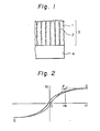
- the magnetic layer in the vertical magnetic recording medium of the present invention has columnar structures oriented in the direction vertical to the surface of the subtrate, which are spaced from one another through fine voids.
- FIG. 1 illustrates an embodiment of the vertical magnetic recording medium of the present invention.
- reference numerals 1,2,3 and 4 represent columnar structures, voids, a magnetic layer and a substrate, respectively.
- the vertical magnetic recording medium of the present invention comprises the substrate 4 and the magnetic layer 3 formed thereon, which consists of columnar structures 1 oriented vertically to the surface of the substrate and spaced from one another voids 2.
- the columnar structures are composed substantially of a metal.
- the metal oxide there can be mentioned CoO, C 02 0 3 , Co 3 0 4 , FeO, a-Fe 2 0 3 , Fe 3 0 4 and CoFe 2 0 4 .
- At least one specific crystal axis be an easily magnetizing axis.
- the weight ratio of cobalt to CoO is preferably from 80/20 to 20/80, and more preferably from 70/30 to 35/65.
- the weight ratio of iron to Fe 3 0 4 is preferably from 7/93 to 50/50, and more preferably from 21/79 to 47/53.
- Fine voids must be present among the columnar structures in the magnetic layer at a void ratio of 7 to 56%. If the void ratio exceeds 56%, the saturation magnetization is reduced and hence, the magnetic characteristics in the vertical direction are reduced, and moreover, the mechanical strength of the magnetic layer is reduced. If the void ratio is lower than 7%, the effect of manifesting the magnetic anisotropy in the vertical direction is insufficient. In order to further enhance the magnetic characteristics in the vertical direction, it is more preferred that the void ratio be in the range from 19 to 52%.
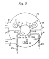
- the anisotropic magnetic field (Hk) As the parameter indicating the magnetic anisotropy of the vertical magnetic recording medium, there can be mentioned the anisotropic magnetic field (Hk). The larger is this value, the more easily magnetized in the vertical direction is the vertical magnetic recording medium. In oher words, a vertical magnetic recording medium having a large value of the anisotropic magnetic field is excellent.
- the method for determining the anisotropic magnetic field (Hk) will now be described with reference to Fig. 2.
- 0 represents the origin
- the magnetization intensity (M) of the magnetized magnetic layer is plotted on the oridinate
- the external magnetic field (H) applied to the magnetic layer is plotted on the abscissa.
- the value of the external magnetic field (H) at the crossing point F between the tangential line drawn to the hysteresis loop from the origin O and the line passing through the positive saturation magnetization point D and drawn in parallel to the abscissa of the external magnetic field (H) indicates the anisotropic magnetic field (Hk).
- the magnetic layer of the present invention comprises columnar structures composed of a metal selected from cobalt and iron, and an oxide of the metal and fine voids.
- the thickness of the magnetic layer is not particularly limited, but a practical range of thickness is from 0.02 to 5 pm. In view of the flexibility, the head touch and the film-forming speed of the magnetic layer, it is preferred that the thickness of the magnetic layer be in the range of from 0.05 to 2.0 ⁇ m.
- the void ratio is used as the parameter indicating the ratio of the volume occupied by the voids in the magnetic layer.
- the void ratio Vo(%) is expressed by the following formula:
- dw represents the weight film thickness and dv represents the geometrical film thickness.
- the methods for determining the weight film thickness (dw) and the geometrical film thickness (dv) will be described in detail hereinafter.
- the weight film thickness (dw) is obtained by measuring the weight of the magnetic layer and dividing the value of the weight by the density of the magnetic layer.
- the geometrical film thickness (dv) is obtained by directly measuring the thickness of the magnetic layer mechanically by a tracer type surface roughness tester. If there are not present voids such as mentioned above, the weight film thickness (dw) is substantially equal to the geometrical film thickness (dv), and the ratio (dw/dv) of both the values is substantially 1. In other words, the void ratio Vo is 0%. In the magnetic layer of the present invention, because of the presence of voids, the weight film thickness (dw) is smaller than the geometrical film thickness (dv), and the ratio (dw/dv) of both the values is lower than 1.
- the magnetic layer in the present invention has a magnetic anisotropy in the vertical direction to the surface of the substrate and is suitable for the vertical magnetic recording.
- a magnetic layer having a magnetic anisotropy in the horizontal direction to the surface of the substrate is not within the scope of the present invention, even if the material and composition would themselves fall within the limits set out in the claims.
- one or more of undercoating layers may be formed on the substrate.
- a soft magnetic layer be formed between the magnetic layer and the substrate.
- the coercive force of the soft magnetic layer in the horizontal direction to the surface of the substrate is smaller than 35 Oe (2785 A/m), more preferably smaller than 20 Oe (1592 A/m), most preferably smaller than 10 Oe (796 A/m).
- the soft magnetic layer is composed mainly of iron and nickel, and manganese, molybdenum, chromium or copper may be incorporated so as to reduce the coercive force and increase the permeability. Addition of molybdenum or copper is especially effective and preferred for reducing the coercive force and increasing the permeability. An iron/nickel weight ratio approximating to 20/80 or 50/50 is preferred for reducing the coercive force and increasing the permeability.
- compositions comprising additive elements in addition to iron and nickel as the main elements, there are preferably used compositions close to the following weight ratios: 21.2 iron/78.5 nickel/0.3 manganese, 15.7 iron/79.0 nickel/5.0 molybdenum/0.3 manganese, 18.0 iron/75.0 nickel/2.0 chromium/5.0 copper, 17.7 iron/78.5 nickel/3.8 chromium, 16.0 iron/80.0 nickel/4.0 molybdenum and 14.0 iron/77.0 nickel/ 5.0 copper/4.0 molybdenum.
- This soft magnetic layer may be formed according to the vacuum deposition method such as vacuum vapor deposition, ion plating or sputtering, but vacuum vapor deposition is especially preferred because the substrate temperature is not to a high temperature elevated and the film-forming speed is high.
- the vacuum vapor deposition referred to herein includes electron beam vacuum deposition, induction heating vacuum deposition, resistance heating vacuum deposition and laser heating vacuum deposition.
- the kind of the substrate is not particularly limited.
- metals such as aluminum, copper, iron and stainless steel, inorganic materials such as glass and ceramics, and organic polymeric materials such as plastic films.
- organic polymeric materials for example, polyesters such as polyethylene terephthalate, polyethylene naphthalate, polyethylene dicarboxylate and polyethylene-a, ⁇ 3-bis(2-chlorophenoxy)ethane-4,4'-dicarboxylate, polyolefins such as polyethylene, polypropylene and polybutene, polymethyl methacrylate, polycarbonates, polysulfones, polyamides, aromatic polyamides, polyphenylene-sulfide, polyphenylene-oxide, polamide-imides, polyimides, polyvinyl chloride, polyvinylidene chloride, polytetrafluoroethylene, acetyl cellulose, methyl
- a biaxially oriented film or sheet is especially suitable because the flatness and dimensional stability are excellent, and a biaxially oriented film or sheet of a polyester, polyphenylene-sulfide or aromatic polyamide is especially preferred.
- the shape of the substrate is not particularly limited, and it may be in the form of a drum, disk, sheet, tape or card.
- the thickness of the substrate is not particularly limited. In the case of a substrate which is in the form of a sheet, tape or card, in view of the processability and dimension stability, it is preferred that the thickness of the substrate be 2 to 500 pm, more preferably 4 to 200 um.
- the substrate used in the present invention may be subjected to various surface treatments or preliminary treatments for imparting an easy bondability, an improved flatness, a coloring effect, an antistatic effect and an abrasion resistance to the substrate before the formation of the magnetic layer on the substrate.
- a method suitable for preparing the vertical magnetic recording medium of the present invention is a novel reactive vacuum deposition process described in detail hereinafter.
- this novel process of the present invention is characterized in that the vapor stream is incident on the substrate at an incident angle of not larger than 45 degrees and at least one gas chemically inactive in the vacuum deposition system and oxygen are introduced at a ratio of 10/90 to 85/15 by volume into the vacuum chamber to an extent such that the pressure is 1 x 10- 3 to 5 x 10⁻²Torr (133.3 x 10- 3 Pa to 666.6 x 10 -2 Pa) within the vicinity of the substrate.
- any of resistance heating vacuum deposition, induction heating vacuum deposition, electron beam vacuum deposition, ion plating, ion beam vacuum deposition, laser heating vacuum deposition and arc discharge vacuum deposition may be adopted as the vacuum deposition method.
- a travelling system for a continuous substrate composed of an organic polymer comprises an unwinder 11, a nip roll 12, a main drum 13, a nip roll 14 and a winder 15.
- the organic polymer substrate 16 is wound in the form of a roll on the unwinder 11.
- the film 16 isrolled out from the unwinder 11 and passed through the nip roll 12, the main drum 13 and the nip roll 14, and the film 16 is wound on a winding core mounted on the winder 15.
- the main drum 13 has cooling means (not shown) for cooling the back surface of the organic polymer substrate 16, for example, with circulating cold water.
- the vacuum chamber 20 is divided into an upper chamber 25 and a lower chamber 26 by a partition wall 24, and the upper and lower chamber 25 and 26 have exhaust openings 21 and 22, respectively.
- a shielding plate 17 is disposed to restrict the incident angle of a vapor stream formed by evaporation.
- the incident angle is meant an angle 8 formed between the evaporant vapor stream A incident on the substrate surface C and the normal line B to the substrate surface C in Fig. 4.
- An opening 27 is formed on the shielding plate 17 shown in Fig. 3 so that the vapor stream having an incident angle exceeding a predetermined angle of less than 45° is not incident on the substrate surface.
- Refeence numeral 18 represents an electron beam evaporator.
- the vertical magnetic recording medium is prepared according to the preparation process of the present invention by using the apparatus having the abovementioned structure.
- the apparatus that can be used in the present invention is not limited to one described above.
- an organic polymeric material for example, a polyethylene terephthalate film
- a chemically inactive gas and an oxygen gas are introduced from a variable leak valve 23 to the vicinity of the substrate through an introduction pipe 28 so that a predetermined pressure within a range of from 1 x 10- 3 to 5 x 10- 2 Torr (0.133 to 6.67 Pa) is produced in the vicinity of the substrate.
- a predetermined pressure within a range of from 1 x 10- 3 to 5 x 10- 2 Torr (0.133 to 6.67 Pa) is produced in the vicinity of the substrate.
- the pressure in the vicinity of the substrate be from 2 x 10- 3 to 2 x 10- 2 Torr (0.267 to 2.67 Pa).
- the volume ratio of the chemically inactive gas to the oxygen gas is in the range of from 10/90 to 85/15. If the ratio of the oxygen gas exceeds 90% by volume, the oxygen gas undergoes violent gettering, and therefore, the pressure in the vicinity of the substrate is changed and no stable magnetic characteristics can be obtained. Moreover, cracks are formed on the surface of the formed magnetic layer and the coercive force in the vertical direction and the anisotropic magnetic field are reduced. If the ratio of the oxygen gas is lower than 15% by volume, the coercive force in the vertical direction and the anisotropic magnetic field are degraded and the evaporation rate is reduced.
- the oxygen gas be introduced from the downstream side reltively to the moving direction of the substrate, the chemically inactive gas be introduced from the upstream side relatively to the moving direction of the substrate and both the gases be thus supplied to the vicinity of the substrate.
- the central portion of a partition wall is bent toward the lower chamber in the vicinity of the drum to form side wall portions 30A and 30B having a predetermined length.
- Gas supply chambers 29A and 29B are defined by the side wall portions 30A and 30B, the shielding plate 17 and the lower peripheral surface of the main drum 13.
- the top ends of the central bent portions of the partition wall 24, that is, the top ends of the side wall portions 30A and 30B be arranged to lie close to the surface of the main drum 13, as shown in Fig. 5.
- the shielding plate 17 be brought as close to the lower surface of the main drum as possible.
- the gases to be introduced into the vacuum atmosphere are passed through gas control valves 23A and 23B and gas supply pipes 28A and 28B and are supplied into gas supply chambers 29A and 29B.
- the gas control valves 23A and 23B have a function to detect and control the gas flow rate.
- the vacuum chamber 20 is evacuated through the exhaust openings 21 and 22, so that the pressure in the upper chamber 25 is reduced below 5 x 10- 4 Torr (6.67 x 10- 2 Pa) and the pressure in the gas supply chambers 29A and 29B is reduced below 5 x 10- 5 Torr (6.67 x 10- 3 Pa).
- the chemically inactive gas is introduced into the gas supply chamber 29A located upstream relatively to the moving direction of the substrate from the gas flow rate control valve 23A through the introduction pipe 28A.
- the oxygen gas is introduced into the gas supply chamber 29B located downstream relatively to the moving direction of the substrate from the gas flow rate control valve 23B through the introduction pipe 28B.
- the chemically inactive gas is supplied to the magnetic layer-forming zone through the gas supply chamber located upstream relatively to the moving direction of the substrate.
- the oxygen gas is supplied to the magnetic layer-forming zone through the gas supply chamber located downstream relatively to the moving direction of the substrate.
- the pressures in the gas supply chambers 29A and 29B are controlled to predetermined levels by the gas flow rate control valves 23A and 23B. Then, the polyethylene terephthalate film as the substrate is travelled, and iron or cobalt is melted and evaporated on the film by electron beam vacuum evaporation, whereby a magnetic layer having a magnetic anisotropy in the vertical direction is continuously formed on the substrate.
- the gas introduced from the downstream side relatively to the moving direction of the substrate is a gas containing oxygen, and a mixture comprising oxygen and the chemically inactive gas may be used. It is preferred that the gas is composed mainly of oxygen, and a gas consisting solely of oxygen is most preferred.
- Fine projections may be present on the surface of the magnetic layer so as to improve the abrasion resistance of the magnetic layer while maintaining a good head touch without increasing the spacing loss.
- the height of the fine projections formed on the surface of the magnetic layer be 80 to 500 A (0.008 to 0.05 pm), more preferably 90 to 300 A (0.009 to 0.03 pm), most preferably 100 to 250 A (0.01 to 0.025 pm).
- the density of the fine projections be 10" to 10 12 projections per square centimeter, more preferably 4 x 10 10 to 8 x 10¹¹ projections per square centimeter, and most preferably 1 x 10¹¹ to 5 x 10¹¹ projections per square centimeter.
- FIG. 6 shows the section of the vertical magnetic recording medium of the present invention in the thickness direction.
- reference numeral 1 represents columnar structures
- reference numeral 4 represents the substrate
- projections 5 are formed as the top ends of the columnar structures 1.
- the height of the projection referred to in the instant specification is expressed by the average value of the height difference between the top portion A and the adjacent trough portion B.
- the sectional view in the thickness direction is determined by the observation by a transmission electron microscope.
- the density of the projections can be calculated based on the observation of the surface of the magnetic layer by a scanning type electron microscope or a field emission scanning electron microscope.
- the magnetic recording medium of the present invention comprising a magnetic layer consisting essentially of a metal selected from cobalt and iron and an oxide of said metal, improvement of the abrasion resistance is practically indispensable.
- the friction coefficient is reduced because of decrease of the area of the contact of the medium with a magnetic head or the like, and therefore, the abrasion is moderated. Since the friction coefficient is reduced, the running property of the medium between the magnetic head and tape guide is improved.
- the fine projections are uniformly present at a high density, when the medium is brought into contact with the magnetic head, the load is dispersed and the force imposed on the portion actually falling in contact with the magnetic head is reduced and the abrasion is moderated. Moreover, the medium is travelled very stably and variations of the reproduction output or noises can be moderated.
- both the fine projections of the magnetic layer per se and the projections formed from the surface of the substrate are present.
- the proportion of the latter projections is preferably reduced. Since the density of the former projections is high and the former projections have a relatively sharp shape and a large surface area, the lubricating property is increased and the adsorbing property is enhanced, and the abrasion resistance is improved.
- an oxygen gas containing at least 20% by volume of a chemically inactive gas is introduced into the vacuum chamber so that the pressure in the vicinity of the substrate is 1 x 10- 3 to 5 x 10- 2 Torr (0.133 to 6.67 Pa) and a metal selected from cobalt and iron is evaporated, fine projections are formed on the surface of the magnetic layer formed on the substrate.
- fine projections composed of parts of the magnetic layer on the surface of the magnetic layer
- a method in which the surface of the formed magnetic layer is subjected to sputter etching Namely, if the magnetic layer is sputtered with an argon gas or the like, the crystal grain boundary portion is selectively etched and fine projections are formed in the remaining portion.
- fine projections can be formed by plasma etching or ion mealing.
- the method for forming fine projections is not limited to those mentioned above.
- a lubricating layer may be formed on the magnetic layer of the present invention so as to improve the lubrication to the head, the abrasion resistance and the running durability.
- the thickness of the lubricating layer is 100 to 1000 ⁇ (0.01 to 0.1 ⁇ m), preferably 100 to 400 A (0.01 top 0.04 pm). If the thickness is smaller than 100 A (0.01 ⁇ m), the effect of improving the slip characteristics is insufficient, and if the thickness is larger than 1000 A (0.1 pm), the spacing loss at the time of recording and reproducing is increased because of the thickness and the magnetic recording medium is not suitable for high-density recording.
- a fluorine-containing organic compound is preferably used as the lubricant.
- perfluoroalkanes and perfluoroalkyl polyethers are preferred.
- polymeric compounds having a main chain composed of carbon or carbon and oxygen, and the main chain saturated with fluorine or being terminated with fluorine or a polar group are preferably used.
- the polar group there are preferably used -OH, -NH 2 , -N0 2 , -CN, ethylene oxide, carboxylic acid, carboxylic acid salt, sulfonic acid and sulfonic acid salt.
- a carboxylic acid or carboxylic acid salt group is preferred because it shows a high adhesion to the magnetic layer composed of iron or cobalt and an oxide of iron and cobalt.
- the molecular weight of the fluorine-containing organic compound is preferably 1000 to 10000 and more preferably 2000 to 8000. If the molecular weight is lower than 1000, the lubricating layer is readily peeled. If the molecular weight is higher than 1000, the viscosity becomes too high and attainment of the effect of improving the slip characteristics cannot be expected.
- the lubricating layer may be formed directly on the magnetic layer or through a protecting layer. Even if a single lubricating layer is formed, there can be attained effects of improving the slip characteristics, the abrasion resistance and the running durability, but best results are obtained if a laminate structure comprising a layer of a polar group-containing lubricant and a layer of a polar group-free lubricant is used.
- the lubricating layer may be formed by any of the bar coating method, the dip coating method, the spin coating method and the vacuum deposition method, though the method for formation of the lubricant layer is not limited to those mentioned above.
- a chemically inactive gas selected from nitrogen, argon, helium, neon, xenon, radon, methane and ethane be introduced together with oxygen.
- This chemically inactive gas makes a contribution to elevation of the pressure of the vacuum deposition atmosphere, that is, the pressure in the vicinity of the substrate.
- the chemically inactive gas does not participate in chemical reaction with the evaporated metal. Therefore, it is considered that substantially all of the introduced chemically inactive gas exerts a function to elevate the pressure in the vacuum deposition atmosphere. It is considered that by elevation of the pressure in the vacuum deposition atmosphere, constituent particles of the formed magnetic layer are appropriately grown and a columnar structure oriented in the vertical direction to the substrate is definitely formed. Simultaneously, fine voids are formed among these columnar structures. The presence of these voids among the columnar structures is an important requirement of the present invention. It is presumed that the voids will exert the following functions.
- a tape-like or disk-like vertical magnetic recording medium can be prepared on an industrial scale by forming a magnetic layer continuously on a substrate of an organic polymer film.
- the coersive force (Hc) is determined.
- Hc coersive force
- the measurement is effected in the depth direction of the magnetic layer by X-ray photoelectron spectroscopy and Auger electron spectroscopy using a spectroscopy Model ESCALAB-5 supplied by V. G. Scientific Co.
- the beam voltage is 3 KV, and etching in the depth direction is carried out by the Ar ion etching method.
- the electron diffraction pattern is observed by using a transmission electron microscope (Model H-600 or H-800 supplied by Hitachi K.K.) at an acceleration voltage of 100 KV.
- the laser Raman micro-probe used is one supplied under the tradename of "MOLE” by Jovan Ebon Co., and the light source used is Ar laser having a wavelength of 5145 ⁇ (0.5145 pm).
- the analysis is carried out in the same manner as described above with reference to the analysis of the composition of the magnetic layer.
- the quantitative analysis of iron and triiron tetra oxide (Fe 3 0 4 ) is carried out by using a y-ray electron Môsbauer spectrophotometer.
- a gas flow type counter (Model BSD-2400 supplied by Austin Science Co.) is 'used as the detector of the Mösbauer spectrophotometer.
- the weight thickness of the magnetic layer is calculated from the weights of the metal and metal oxide obtained in the quantitative analysis described in (3) above according to the following formula:
- dw stands for the weight thickness (cm) of the magnetic layer
- dm stands for the weight (g/ cm 2 ) of the metal per unit area
- do stands for the weight (g/cm 2 ) of the metal oxide per unit area
- pm stands for the density (g/cm 3 ) of the metal
- po stands for the density (g/cm 3 ) of the metal oxide.
- An electrolyte "R-57” (supplied by Densoku Kogyo K.K.) or 1/10N HCI is dropped on a magnetic layer of a magnetic recording medium sample cut out in an appropriate size to remove a part of the magnetic layer and form a step. After water washing and drying, the thickness of the step is measured as the geometrial thickness (dv) of the magnetic layer by using a tracer type surface roughness tester (universal surface configuration measuring device Model "SE-3E” supplied by Kosaka Kenkyusho K.K.).
- An ultra-thin slice is cut out from the magnetic recording medium and the sectional structure of the magnetic layer is observed by a transmission electron microscope (Model H-600 or H-800 supplied by Hitachi K.K.) at an acceleration voltage of 100 KV.
- the average value of the height difference between the top A of the projection on the surface and the trough B adjacent to this top is designated as the projection height.
- the projection height is thus determined from a photograph of an ultra-thin slice of the magnetic layer.
- a pressure-measuring probe be disposed as close to the substrate as possible within a range not disturbing formation of a layer on the surface of the substrate.
- the pressure-measuring probe is arranged at a point within a linear distance of 500 mm from the center of within a linear distance of 500 mm fromt he center of formation of the magnetic layer.
- Use of a pressure gauge which is hardly influenced by an oxygen gas, such as a Schultz gauge, a Penning gauge or a diaphram pressure gauge is preferred.
- a specimen having a size of 200 mm x 200 mm is cut out from a sample having a magnetic layer formed on one surface of a substrate, and the magnetic layer is coated with a trichlorotrifluoroethane solution containing 0.5% of a perfluoroalkyl-polyether (having a molecular weight of 6500) cotnaining a terminal carboxylic acid group by the bar coating method and is then dried to form a lubricating layer having a thickness of 400 A (0.04 pm).
- a floppy disk having a diameter of 5.25 inches is taken out from the specimen and is used as a test sample.
- EpO the reproducing output at this time
- Ep10/EpO The ratio of the outputs Ep0 and Ep10 (Ep10/EpO) is used as a parameter indicating the durability. The closer to 1 is the output ratio Ep10/EpO, the better is the durability.
- a double-face type head having a pair of a button type head and gimbal type head is used as the magnetic head, and the head pressure is about 15 g.
- the rotation number of the floppy disk is 300 rpm.
- a sample having size of 30 mm x 30 mm is cut out from a magnetic recording medium and allowed to stand still in an atmosphere at a temperature of 60°C and a relative humidity of 90% for 10 weeks.
- the corrosion state of the magnetic layer is evaluated with the naked eye. When discoloration, rusting, blistering or peeling is caused, it is judged that corrosion has taken place.
- the marks in the column "moisture
- the electron beam vacuum deposition apparatus shown in Fig. 3 was evacuated so that the pressure in the upper chamber was reduced below 5 x 10- 4 Torr (6.67 x 10- 2 Pa) and the pressure in the vicinity of the substrate in the lower chamber was reduced below 1 x 10- 5 Torr (1.33 x 10- 3 Pa).
- a mixed gas of nitrogen and oxygen was introduced into the lower chamber through a variable leak valve, and a biaxially, oriented polyethylene terephthalate film having a thickness of 50 pm was travelled at a predetermined running speed. Iron was melted and evaporated by electron beam evaporation, and a magnetic layer was continuously formed on the film.
- the mixing ratio of nitrogen and oxygen in the mixed gas and the introduction rate of the mixed gas flow were charged and the pressure in the vicinity of the substrate was changed within the range of from 1 x 10- 3 to 5 x 10- 2 Torr (0.133 to 6.67 Pa), and various magnetic layers were prepared (Examples 1 through 4).
- a mixed gas of argon and oxygen was introduced and the pressure in the vicinity of the substrate was changed within a range of from 1 x 10- 3 to 5 x 10- 2 Torr (0.133 to 6.67 Pa), and magnetic layers were prepared (Examples 5 and 6).
- the running speed of the polyethylene terephthalate film as the substrate was controlled so that the thickness of the magnetic layer was 2000 to 3000 A (0.2 to 0.3 gm).
- the power supplied to the electron beam evaporator was kept constant at 4 Kw.
- the electron beam vacuum deposition apparatus shown in Fig. 3 was evacuated so that the pressure in the upper chamber was reduced below 5 x 10- 4 Torr (6.67 x 10- 2 Pa) and the pressure in the vicinity of the substrate in the lower chamber was reduced below 1 x 10- 5 Torr (1.33 x 10- 3 Pa).
- a mixed gas of nitrogen and oxygen was introduced into the lower chamber through a variable leak valve.
- a biaxially oriented polyethylene terephthalate film having a thickness of 50 pm was travelled at a predetermined running speed. Cobalt was melted and evaporated by electron beam evaporation, and a magnetic layer was continuously formed on the film.
- the introduced gas, the composition of the introduced gas, the pressure in the vicinity of the substrate, the diameter of columnar structures, the void ratio in the magnetic layer, the ratio of cobalt and cobalt monoxide in the columnar structures and the presence or absence of cracks in the magnetic layer are shown in Table 4.
- the diameter of the columnar structures was appropriate and the ratio of cobalt to cobalt monoxide in the columnar structures was appropriate. Furthermore, since there were present voids among the columnar structures, the magnetic characteristics in the vertical direction were excellent and no cracks were present on the surface of the magnetic layer. Accordingly, these products were very excellent as the vertical magnetic recording medium for high-density recording.
- the electron beam vacuum deposition apparatus shown in Fig. 3 was evacuated so that the pressure in the upper chamber was reduced below 5 x 10- 4 Torr (6.67 x 10 -2 Pa) and the pressure in the vicinity of the substrate in the lower chamber was reduced below 1 x 10- 5 Torr (1.33 x 10- 3 Pa).
- a mixed gas of nitrogen and oxygen was introduced into the lower chamber through a variable leak valve.
- a biaxially oriented polyethylene terephthalate film was travelled at a predetermined running speed. Iron or cobalt was melted and evaporated by electron beam evaporation, and a magnetic layer having a length of about 80 m was continuously formed on the film.
- a shielding plate having such an opening that the incident angle of the vapor stream was smaller than 26° was arranged, and the back surface of the polyethylene terephthalate film was cooled below 50°C by a cooling drum.
- a mixed gas comprising nitrogen and oxygen at a volume ratio of 79/21 was introduced so that the pressure in the vicinity of the substrate was 4.8 x 10- 3 Torr (6.39 x 10 -1 Pa) and cobalt was evaporated (Example 10).
- a mixed gas comprising nitrogen and oxygen at a volume ratio of 55/45 was introduced so that the pressure in the vicinity of the substrate was 3.2 x 10- 3 Torr (4.27 x 10 -1 Pa), and cobalt was evaporated (Example 11).
- a mixed gas comprising nitrogen and oxygen at a volume ratio of 30/70 was introduced so that the pressure in the vicinity of the substrate was 2.4 x 10- 3 Torr (3.2 x 10 -1 Pa), and cobalt was evaporated (Example 12).
- a mixed gas comprising nitrogen and oxygen at a volume ratio of 5/95 was introduced so that the pressure in the vicinity of the substrate was 5.2 x 10- 3 Torr (6.93 x 10 -1 Pa), and cobalt was evaporated (Comparative Example 10).
- Oxygen alone was introduced so that the pressure in the vicinity of the substrate was 2.0 x 10- 3 Torr (2.67 x 10 -1 Pa), and iron was evaporated (Comparative Example 11).
- Comparative Example 12 a vertical magnetic layer composed mainly of iron oxide was formed by magnetron sputtering in the following manner.
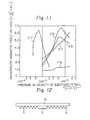
- a target used for sputtering in Comparative Example 12 is shown in a diagram of Fig. 12.
- Reference numeral 6 represents a copper disk having a diameter of 6 inches and a thickness of 3 mm
- reference numeral 7 represents a ring of iron having a purity higher than 99.9%, which has a triangular section.
- the target comprises the iron rings 7 arranged concentrically and attached to the copper disk 6.
- the above-mentioned iron target was attached to a target holder of a magnetron sputtering apparatus (supplied by Niommen Anelva K.K.) through a copper disk having a diameter of 6 inches (152.4 mm) and a thickness of 3 mm.
- a heating drum is arranged in the apparatus to confront the target, and a winder and an unwinder are arranged before and after the drum.
- a vacuum chamber in the above-mentioned apparatus was evacuated until the pressure was reduced below 1 x 10- 6 Torr (1.33 x 10- 4 Pa).
- a mixed gas comprising argon and oxygen at a volume ratio of 70/30 was introduced so that the pressure in the vacuum chamber was 4 x 10- 3 Torr (5.33 x 10 -1 Pa).
- a direct current power of about 2.0 Kw was applied.
- a polyethylene terephthalate film having a thickness of 25 pm was travelled at a speed of about 0.1 m/min. Thus, a magnetic layer was continuously formed on the film.
- the temperature of the drum was maintained at 80°C.
- the pressure in the vicinity of the substrate was stable during formation of the magnetic layer and the pressure variation was in the range of from ⁇ 1 x 10- 4 to ⁇ 3 x 10- 4 Torr ( ⁇ 1.33 x 10- 2 to ⁇ 4 x 10- 2 Pa), and the variation of magnetic properties in the travelling direction of the film was small.
- Ultra-thin slices were cut out from the magnetic-layers obtained in Examples 10 through 14 and Comparative Examples 9 through 12 and photographs of the sections were taken.
- Examples 10 through 14 definite columnar structures were observed, and fine projections were formed on the top ends of the columnar structures.
- Comparative Examples columnar structures were observed but they were very indefinite. The number of voids was very small, and the columnar structures were densely aggregated. Moreover, the height of the fine projections formed on the top ends of the columnar structures was small and the magnetic layer was relatively flat.
- the product of each of Examples 10 through 14 was a vertical magnetic recording medium excellent in the magnetic characteristics because both the vertical coercive force and the anisotropic magnetic field were high. Because of the presence of fine projections formed at an appropriate density on the surface of the magnetic layer and having an appropriate height, the durability was very excellent.
- the electron beam vacuum deposition apparatus shown in Fig. 5 was evacuated so that the pressure in the upper chamber was reduced below 5 x 10- 4 Torr (6.67 x 10- 2 Pa) and the pressure in the gas supply chamber was reduced below 5 x 10- 5 Torr (6.67 x 10- 3 Pa).
- a chemically inactive gas was introduced on the upstream side relatively in the travelling direction of the substrate.
- an oxygen-containing gas was introduced on the downstream side relatively to the travelling direction of the substrate.
- a biaxially oriented polyethylene terephthalate film having a thickness of 50 pm was travelled at a predetermined running speed, and cobalt or iron was melted and evaporated by electron beam evaporation and a magnetic layer was continuously formed on the film.
- a shielding plate having such an opening that the incident angle of the vapor stream was smaller than 26° was arranged, and the back surface of the polyethylene terephthalate film was maintained below 50°C by a cooling drum.
- An electron beam evaporator Model EGL-110 supplied by Nippon Shinku Gijutsu K.K. was used and a power source Model HP-1610F supplied by Nippon Shinku Gijutsu K.K. was used as the power source for the electron beam evaporator.
- Cobalt or iron having a purity higher than 99.9% was placed in the concave portion of the electron beam evaporator.
- magnetic layers were formed by changing the gas introduced on the upstream side relatively to the travelling direction of the substrate, the gas introduced on the downstream side, the supply ratio of both the gases (flow amount of the gas introduced on the upstream side/the flow amount of the gas introduced on the downstream side) and the gas supply chamber pressure as shown in Table 7 (Examples 15 through 20).
- the gas introduced on the downstream side was oxygen or an oxygen-containing mixed gas.
- Examples 25 through 30 satisfy claim 13, but do not satisfy claims 14 and 15. These examples are recited for comparison purposes to show that the processes described in claims 14 and 15, (which are supported by Examples 15 through 20) are preferable for improving the moisture resistance and the abrasion resistance.
- the thickness of the magnetic layer was adjusted to 2000 to 3000 A (0.2 to 0.3 pm) by controlling the travelling speed of the polyethylene terephthalate film as the substrate.
- the electric power applied to the vertical electron beam evaporator was kept constant at - 4 Kw.
- the vertical magnetic recording medium prepared in Example 11 was cut into a size of 200 mm x 250 mm.
- a trichlorotrifluoroethane solution of a perfluoroalkyl polyether (having a molecular weight of 2500) having a terminal sulfonic acid group was coated on the magnetic layer by the bar coating method to form a lubricating layer having a thickness of 200 A (0.02 pm).
- a lubricating layer of a perfluoroalkyl polyether (having a molecular weight of 3000) having no polar group, which has a thickness of 200 A (0.02 pm) was formed on the above lubricating layer.
- the sample was punched into a floppy disk having a diameter of 5.25 inches, and the disk was contained in a jacket (Example 22).
- the sample was punched into a floppy disk having a diameter of 5.25 inches, and the disk was contained in a jacket (Comparative Example 13).
- a lubricating layer of a perfluoroalkyl polyether having a molecular weight of 4500 having a terminal carboxylic acid group, which had a thickness of 400 A (0.04 um) was formed on the magnetic layer of the vertical magnetic recording medium prepared in Example 11 according to the bar coating method.
- the sample was punched into a floppy disk having a diameter of 5.25 inches and the disk was contained in a jacket (Comparative Example 14).
- the electron beam vacuum evaporation apparatus shown in Fig. 3 was evacuated so that the pressure in the upper chamber was reduced below 5 x 10 -4 Torr (6.67 x 10 -2 Pa) and the pressure in the vicinity of the substrate in the lower chamber was reduced below 1 x 10- 5 Torr (1.33 x 10- 3 Pa).
- a biaxially oriented polyethylene terephthalate film having a thickness of 50 pm was travelled at a predetermined running speed, and an iron-83% by weight nickel alloy was melted and evaporated by electron beam evaporation and a soft magnetic layer was continuously formed on the film.
- a shielding plate having such an opening that the incident angle of the vapor stream was smaller than 16% was arranged in the vacuum deposition apparatus.
- a magnetic layer having a magnetic anisotropy in the vertical direction was formed on the thus-formed soft magnetic layer under the same conditions as in Example 8 where the pressure in the vicinity of the substrate was 2 x 10- 3 Torr (2.67 x 10 -1 Pa), whereby a magnetic recording medium was prepared (Example 23).
- the magnetic recording medium was punched into a floppy disk shape having a diameter of 5.25 inches and contained in a jacket.
- the main pole was brought in contact with the magnetic layer of the medium, and the auxiliary pole was arranged to confront the main pole with the medium being interposed therebetween and the auxiliary pole was separated from the medium by about 100 pm.
- the medium was turned at 1800 rpm and a square wave of 2 MHz was recorded. The recording current was selected so that the reproducing output was largest.
Landscapes
- Physics & Mathematics (AREA)
- Spectroscopy & Molecular Physics (AREA)
- Manufacturing Of Magnetic Record Carriers (AREA)
- Magnetic Record Carriers (AREA)
Claims (15)
Applications Claiming Priority (4)
| Application Number | Priority Date | Filing Date | Title |
|---|---|---|---|
| JP5517084A JPS60201520A (ja) | 1984-03-22 | 1984-03-22 | 垂直磁気記録媒体 |
| JP55170/84 | 1984-03-22 | ||
| JP21441284A JPS6194237A (ja) | 1984-10-15 | 1984-10-15 | 垂直磁気記録媒体の製造方法 |
| JP214412/84 | 1984-10-15 |
Publications (3)
| Publication Number | Publication Date |
|---|---|
| EP0156625A2 EP0156625A2 (de) | 1985-10-02 |
| EP0156625A3 EP0156625A3 (en) | 1986-12-30 |
| EP0156625B1 true EP0156625B1 (de) | 1989-10-04 |
Family
ID=26396034
Family Applications (1)
| Application Number | Title | Priority Date | Filing Date |
|---|---|---|---|
| EP85301944A Expired EP0156625B1 (de) | 1984-03-22 | 1985-03-20 | Vertikaler magnetischer Aufzeichnungsträger und Verfahren zu seiner Herstellung |
Country Status (4)
| Country | Link |
|---|---|
| US (2) | US4726988A (de) |
| EP (1) | EP0156625B1 (de) |
| CA (1) | CA1235808A (de) |
| DE (1) | DE3573482D1 (de) |
Families Citing this family (30)
| Publication number | Priority date | Publication date | Assignee | Title |
|---|---|---|---|---|
| JPS62208412A (ja) * | 1986-03-07 | 1987-09-12 | Hitachi Ltd | 磁気記録媒体およびその製造方法 |
| US4975324A (en) * | 1986-10-21 | 1990-12-04 | Matsushita Electric Industrial Co., Ltd. | Perpendicular magnetic film of spinel type iron oxide compound and its manufacturing process |
| JPH0654533B2 (ja) * | 1987-02-04 | 1994-07-20 | 富士写真フイルム株式会社 | 磁気記録媒体 |
| US5244751A (en) * | 1988-03-11 | 1993-09-14 | Hitachi, Ltd. | Perpendicular magnetic recording medium, its fabrication method and read-write machine using it |
| JPH01248312A (ja) * | 1988-03-29 | 1989-10-03 | Kanegafuchi Chem Ind Co Ltd | 垂直磁気記録媒体 |
| NL8802960A (nl) * | 1988-12-01 | 1990-07-02 | Philips Nv | Systeem omvattende een magneetkop en een verplaatsbare magnetische informatiedrager, alsmede een magneetkop en een magnetische informatiedrager geschikt voor toepassing in het systeem. |
| US5320881A (en) * | 1991-08-27 | 1994-06-14 | Northeastern University | Fabrication of ferrite films using laser deposition |
| US5227204A (en) * | 1991-08-27 | 1993-07-13 | Northeastern University | Fabrication of ferrite films using laser deposition |
| DE4443530A1 (de) * | 1993-12-16 | 1995-06-22 | Basf Magnetics Gmbh | Magnetisches Aufzeichnungsmedium und Verfahren zur Herstellung desselben |
| JP3491942B2 (ja) * | 1994-01-31 | 2004-02-03 | 富士写真フイルム株式会社 | 磁気記録媒体 |
| US5650889A (en) * | 1994-02-07 | 1997-07-22 | Hitachi, Ltd. | Magnetic recording medium containing heavy rare gas atoms, and a magnetic transducing system using the medium |
| JPH09501790A (ja) * | 1994-06-09 | 1997-02-18 | フィリップス エレクトロニクス ネムローゼ フェンノートシャップ | 磁気−光学記録媒体 |
| JPH08102034A (ja) * | 1994-09-19 | 1996-04-16 | Minnesota Mining & Mfg Co <3M> | 磁気記録媒体 |
| JPH103638A (ja) * | 1996-06-18 | 1998-01-06 | Sony Corp | 磁気記録媒体 |
| US6231968B1 (en) * | 1997-09-04 | 2001-05-15 | Matsushita Electric Industrial Co., Ltd. | Magnetic thin film and magnetic device using the same |
| JPH11189874A (ja) * | 1997-12-25 | 1999-07-13 | Tdk Corp | 薄膜形成方法および装置 |
| US6428848B1 (en) * | 1998-08-06 | 2002-08-06 | Toray Industries, Inc. | Method for producing a metal evaporated article |
| EP1223457A4 (de) * | 1999-10-15 | 2004-10-13 | Hitachi Ltd | Optisches funktionelles element, dessen herstellungsverfahren und anwendung |
| EP1174526A1 (de) * | 2000-07-17 | 2002-01-23 | Nederlandse Organisatie voor Toegepast Natuurwetenschappelijk Onderzoek TNO | Kontinuierliches Abscheiden aus der Gasphase |
| JP4234338B2 (ja) * | 2001-12-21 | 2009-03-04 | Tdk株式会社 | フィルムの蒸着方法 |
| EP1660565A1 (de) * | 2003-08-20 | 2006-05-31 | Dow Corning Corporation | Carbazolylfunktionelle polysiloxanharze, silikonzusammensetzung und organische lichtemittierende diode |
| WO2005019307A1 (en) * | 2003-08-20 | 2005-03-03 | Dow Corning Corporation | Carbazolyl-functional cyclosiloxane, silicone composition, and organic light-emitting diode |
| WO2005019308A1 (en) * | 2003-08-20 | 2005-03-03 | Dow Corning Corporation | Carbazolyl-functional linear polysiloxanes, silicone composition, and organic light-emitting diode |
| US20050181239A1 (en) * | 2004-02-12 | 2005-08-18 | Seagate Technology Llc | Granular magnetic recording media with improved corrosion resistance by pre-carbon overcoat ion etching |
| US20070087227A1 (en) * | 2005-10-14 | 2007-04-19 | Seagate Technology Llc | Granular magnetic recording media with improved corrosion resistance by cap layer + pre-covercoat etching |
| US7691499B2 (en) * | 2006-04-21 | 2010-04-06 | Seagate Technology Llc | Corrosion-resistant granular magnetic media with improved recording performance and methods of manufacturing same |
| JP4288297B1 (ja) * | 2008-01-09 | 2009-07-01 | 三菱重工業株式会社 | 圧力制御装置および圧力制御方法 |
| JP5513479B2 (ja) * | 2008-03-26 | 2014-06-04 | ダウ・コーニング・コーポレイション | シリコーン組成物および有機発光ダイオード |
| US20100092802A1 (en) * | 2008-10-15 | 2010-04-15 | Seagate Technology Llc | Multi-step etch process for granular media |
| GB2559685B (en) | 2015-03-10 | 2019-06-12 | Bobst Manchester Ltd | Vacuum Coater For Coating A Web |
Family Cites Families (23)
| Publication number | Priority date | Publication date | Assignee | Title |
|---|---|---|---|---|
| GB1599161A (en) * | 1976-07-15 | 1981-09-30 | Matsushita Electric Industrial Co Ltd | Magnetic recording medium and method of making the same |
| JPS54124708A (en) * | 1978-03-20 | 1979-09-27 | Hitachi Maxell | Magnetic record medium |
| DE2839378B1 (de) * | 1978-09-11 | 1979-11-15 | Basf Ag | Magnetischer Aufzeichnungstraeger |
| DE2906787A1 (de) * | 1979-02-22 | 1980-09-04 | Hoechst Ag | Ueberzugsmittel auf basis eines copolymeren aus tetrafluorethylen und einem perfluor(alkylvinyl)-ether |
| DE3024918A1 (de) * | 1979-07-02 | 1981-01-22 | Fuji Photo Film Co Ltd | Magnetisches aufzeichnungsmaterial und verfahren zu dessen herstellung |
| US4452857A (en) * | 1981-01-12 | 1984-06-05 | Shunpei Yamazaki | Magnetic medium |
| JPS57143729A (en) * | 1981-02-27 | 1982-09-06 | Fuji Photo Film Co Ltd | Magnetic recording medium |
| JPS57143728A (en) * | 1981-02-27 | 1982-09-06 | Fuji Photo Film Co Ltd | Magnetic recording medium |
| JPS57152521A (en) * | 1981-03-17 | 1982-09-20 | Matsushita Electric Ind Co Ltd | Magnetic recording medium |
| JPS57152517A (en) * | 1981-03-17 | 1982-09-20 | Matsushita Electric Ind Co Ltd | Magnetic recording medium |
| JPS5834903A (ja) * | 1981-08-27 | 1983-03-01 | Tdk Corp | 磁気記録媒体 |
| DE3232520A1 (de) * | 1981-09-03 | 1983-03-17 | Fuji Photo Film Co., Ltd., Minami-Ashigara, Kanagawa | Verfahren zur herstellung eines magnetischen aufzeichnungstraegers |
| US4388367A (en) * | 1981-09-28 | 1983-06-14 | Xerox Corporation | Perpendicular magnetic recording medium and fabrication |
| US4405677A (en) * | 1981-09-28 | 1983-09-20 | Xerox Corporation | Post treatment of perpendicular magnetic recording media |
| JPS5883328A (ja) * | 1981-11-12 | 1983-05-19 | Fuji Photo Film Co Ltd | 磁気記録媒体 |
| JPS59119538A (ja) * | 1982-12-25 | 1984-07-10 | Tdk Corp | 磁気記録媒体 |
| JPS59160828A (ja) * | 1983-03-01 | 1984-09-11 | Fuji Photo Film Co Ltd | 磁気記録媒体 |
| DE3465647D1 (en) * | 1983-03-08 | 1987-10-01 | Ulvac Corp | A magnetic recording member and a manufacturing method for such a member |
| JPH0766528B2 (ja) * | 1983-03-18 | 1995-07-19 | 富士写真フイルム株式会社 | 磁気記録媒体 |
| JPS59203238A (ja) * | 1983-04-30 | 1984-11-17 | Tdk Corp | 磁気記録媒体の製造方法 |
| US4526833A (en) * | 1983-10-03 | 1985-07-02 | Minnesota Mining And Manufacturing Company | Magnetic recording medium having a perfluoropolyether polymer protective coating |
| GB2149320B (en) * | 1983-10-18 | 1988-02-10 | Tdk Corp | Magnetic recording medium |
| JPS60154323A (ja) * | 1984-01-20 | 1985-08-14 | Sony Corp | 磁気記録媒体 |
-
1985
- 1985-03-18 CA CA000476830A patent/CA1235808A/en not_active Expired
- 1985-03-19 US US06/713,463 patent/US4726988A/en not_active Expired - Fee Related
- 1985-03-20 EP EP85301944A patent/EP0156625B1/de not_active Expired
- 1985-03-20 DE DE8585301944T patent/DE3573482D1/de not_active Expired
-
1988
- 1988-11-02 US US07/267,755 patent/US4888211A/en not_active Expired - Fee Related
Also Published As
| Publication number | Publication date |
|---|---|
| EP0156625A3 (en) | 1986-12-30 |
| CA1235808A (en) | 1988-04-26 |
| US4888211A (en) | 1989-12-19 |
| EP0156625A2 (de) | 1985-10-02 |
| US4726988A (en) | 1988-02-23 |
| DE3573482D1 (en) | 1989-11-09 |
Similar Documents
| Publication | Publication Date | Title |
|---|---|---|
| EP0156625B1 (de) | Vertikaler magnetischer Aufzeichnungsträger und Verfahren zu seiner Herstellung | |
| US4565734A (en) | Magnetic recording medium | |
| US5589263A (en) | Magnetic recording medium having a ferromagnetic metal thin film, a dry etched layer, a carbonaceous film, and a lubricant film | |
| EP0477641A2 (de) | Magnetischer Aufzeichnungsträger für digitale Aufzeichnung | |
| US4835070A (en) | Magnetic recording medium and method of producing the same | |
| US5759710A (en) | Magnetic recording medium with a magnetic layer having a specific oxygen signal strength profile in the thickness direction | |
| US5985423A (en) | Method and device for manufacturing a thin film and magnetic recording medium | |
| Kunieda et al. | Metal evaporated video tape | |
| JP2004046928A (ja) | 磁気記録媒体 | |
| JPH0192924A (ja) | 磁気記録媒体 | |
| JP2794662B2 (ja) | 垂直磁気記録媒体の製造方法 | |
| JPS62103851A (ja) | 垂直磁気記録媒体の製造方法 | |
| JPS61187122A (ja) | 磁気記録媒体 | |
| JPS62109218A (ja) | 垂直磁気記録媒体およびその製造方法 | |
| JPS63138519A (ja) | 垂直磁気記録媒体 | |
| JPH01204219A (ja) | 垂直磁気記録媒体の製造方法 | |
| JPS61214136A (ja) | 磁気記録媒体の製造方法およびその装置 | |
| JPS62214521A (ja) | 磁気記録媒体の製造方法 | |
| JPH01224914A (ja) | 垂直磁気記録媒体 | |
| JPH0916952A (ja) | 磁気記録媒体の製造方法 | |
| JP2002175618A (ja) | 磁気記録媒体 | |
| JP2004273032A (ja) | 磁気記録媒体の製造方法および製造装置 | |
| JPH01303623A (ja) | 磁気記録媒体 | |
| JPH0487024A (ja) | 磁気記録媒体及びその製造方法 | |
| JPH0841644A (ja) | 薄膜形成装置 |
Legal Events
| Date | Code | Title | Description |
|---|---|---|---|
| PUAI | Public reference made under article 153(3) epc to a published international application that has entered the european phase |
Free format text: ORIGINAL CODE: 0009012 |
|
| AK | Designated contracting states |
Designated state(s): BE DE FR GB IT NL |
|
| PUAL | Search report despatched |
Free format text: ORIGINAL CODE: 0009013 |
|
| AK | Designated contracting states |
Kind code of ref document: A3 Designated state(s): BE DE FR GB IT NL |
|
| 17P | Request for examination filed |
Effective date: 19870619 |
|
| 17Q | First examination report despatched |
Effective date: 19880122 |
|
| ITF | It: translation for a ep patent filed | ||
| GRAA | (expected) grant |
Free format text: ORIGINAL CODE: 0009210 |
|
| AK | Designated contracting states |
Kind code of ref document: B1 Designated state(s): BE DE FR GB IT NL |
|
| REF | Corresponds to: |
Ref document number: 3573482 Country of ref document: DE Date of ref document: 19891109 |
|
| ET | Fr: translation filed | ||
| PLBE | No opposition filed within time limit |
Free format text: ORIGINAL CODE: 0009261 |
|
| STAA | Information on the status of an ep patent application or granted ep patent |
Free format text: STATUS: NO OPPOSITION FILED WITHIN TIME LIMIT |
|
| 26N | No opposition filed | ||
| ITTA | It: last paid annual fee | ||
| PGFP | Annual fee paid to national office [announced via postgrant information from national office to epo] |
Ref country code: FR Payment date: 19930309 Year of fee payment: 9 |
|
| PGFP | Annual fee paid to national office [announced via postgrant information from national office to epo] |
Ref country code: GB Payment date: 19930310 Year of fee payment: 9 |
|
| PGFP | Annual fee paid to national office [announced via postgrant information from national office to epo] |
Ref country code: DE Payment date: 19930324 Year of fee payment: 9 |
|
| PGFP | Annual fee paid to national office [announced via postgrant information from national office to epo] |
Ref country code: NL Payment date: 19930331 Year of fee payment: 9 |
|
| PGFP | Annual fee paid to national office [announced via postgrant information from national office to epo] |
Ref country code: BE Payment date: 19930504 Year of fee payment: 9 |
|
| PG25 | Lapsed in a contracting state [announced via postgrant information from national office to epo] |
Ref country code: GB Effective date: 19940320 |
|
| PG25 | Lapsed in a contracting state [announced via postgrant information from national office to epo] |
Ref country code: BE Effective date: 19940331 |
|
| BERE | Be: lapsed |
Owner name: TORAY INDUSTRIES INC. Effective date: 19940331 |
|
| PG25 | Lapsed in a contracting state [announced via postgrant information from national office to epo] |
Ref country code: NL Effective date: 19941001 |
|
| GBPC | Gb: european patent ceased through non-payment of renewal fee |
Effective date: 19940320 |
|
| NLV4 | Nl: lapsed or anulled due to non-payment of the annual fee | ||
| PG25 | Lapsed in a contracting state [announced via postgrant information from national office to epo] |
Ref country code: FR Effective date: 19941130 |
|
| PG25 | Lapsed in a contracting state [announced via postgrant information from national office to epo] |
Ref country code: DE Effective date: 19941201 |
|
| REG | Reference to a national code |
Ref country code: FR Ref legal event code: ST |