EP0162377A2 - Monorail électrique aérien à suspension inférieure - Google Patents
Monorail électrique aérien à suspension inférieure Download PDFInfo
- Publication number
- EP0162377A2 EP0162377A2 EP85105697A EP85105697A EP0162377A2 EP 0162377 A2 EP0162377 A2 EP 0162377A2 EP 85105697 A EP85105697 A EP 85105697A EP 85105697 A EP85105697 A EP 85105697A EP 0162377 A2 EP0162377 A2 EP 0162377A2
- Authority
- EP
- European Patent Office
- Prior art keywords
- rail
- running rail
- vertical web
- running
- flange
- Prior art date
- Legal status (The legal status is an assumption and is not a legal conclusion. Google has not performed a legal analysis and makes no representation as to the accuracy of the status listed.)
- Granted
Links
Images

Classifications
-
- B—PERFORMING OPERATIONS; TRANSPORTING
- B61—RAILWAYS
- B61C—LOCOMOTIVES; MOTOR RAILCARS
- B61C13/00—Locomotives or motor railcars characterised by their application to special systems or purposes
- B61C13/04—Locomotives or motor railcars characterised by their application to special systems or purposes for elevated railways with rigid rails
Definitions
- the invention relates to a lower belt electric monorail system according to the preamble of the main claim.
- a track with a double-T profile is attached to the supporting structure, and the electric hanging vehicles run with two wheels on the lower flange that extends away from the center bar on both sides.
- upper belt electric monorails such as those e.g. are known from DE-AS 25 45 907.
- the impellers attack on the top of the upper flange, while the counter pressure rollers attack on the underside of the lower flange.
- the running rail must be fastened to the supporting structure with the aid of rigid brackets.
- the object of the present invention to provide an electric monorail system, in which the running rail RAG right at the T factory construction is secured and the electric vehicles have an extremely low profile and nevertheless with a simple design. enable problem-free guidance and drive, even on inclines and descents, while the arrangement of the busbar neither places any demands on the overall height of the electric vehicle, nor hinders its free movement.
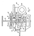
- the lower belt electric monorail system comprises a running rail 10.
- This includes a vertical web 12, from the lower ends of which a lower flange 14 extends to only one side (left in FIG. 1).
- two upper flanges 16 and 18 extend from the upper end of the vertical web 12 on both sides.
- the upper flange 16, which extends to the same side as the lower flange 14, has a greater lateral extent than the other upper flange 18.
- the upper flange 16 is thickened in the area opposite the lower flange 14.
- the underside of the upper flange 16 and the upper side of the lower flange 14 are designed as running surfaces.
- Both on the lower flange 14 and on the upper flange 16, centering pins 20, 22 are provided, which are the positive serve rail connection.
- a support structure 24 shown as a double-T beam is used for direct fastening of the running rail with the aid of fastening clips 26.
- bolts and nuts or the like can of course also be used for fastening. It can also be attached to an existing circular conveyor system.
- the busbars 28 are fastened with the aid of arms 30. Power supply cables, not shown, lead to the busbars 28.
- An electric vehicle generally designated 40, is designed to wrap around the bottom of the track.
- the electric vehicle or the electric trolley 40 comprises a housing 42. This carries a geared motor 44 which drives an impeller 46, as well as a sprocket, not shown, which is arranged concentrically therewith. The latter interacts with chain sections, not shown.
- the impeller is designed as a slip wheel. With regard to further details of the impeller and the chain drive, reference is made to the German patent applications P 31 28 824.3 and P 34 03 460.9. to which express reference is made for the purposes of disclosure.
- the impeller 46 rolls on the top of the lower flange 14 of the running rail 10.
- a roller mounting block 50 is fastened to the housing 42 under prestress by compression springs 52.
- Each roller mounting block 50 carries a counter pressure roller 54, which rolls on the underside of the upper flange 16, which is designed as a running surface.
- the roll holder block carries. 50 each have two support rollers 56 which engage on the side of the vertical web 12 of the running rail 10 facing the running wheel 46.
- the housing 42 has a device 58 for fastening the hanger below the running rail 10, and from this a bearing block 60 extends upwards on the side of the running rail 10 facing away from the running wheel 46 and carries two further support rollers 62 and a spacer bush 64.
- the four support rollers 62 lie approximately opposite the support rollers 56, ie they engage on the side of the vertical web 12 of the running rail 10 facing away from the impeller 46.
- the support rollers 56 are pressed onto the support rollers 62, so that all the support rollers are always held in attack on the vertical web 12 of the running rail 10.
- the busbars 28 are arranged above the support rollers 62.
- the electric vehicle 40 has a current collector 66 which extends upwards between the two pairs of support rollers 62.
- the lower chord electric monorail system according to the invention has an extremely compact structure with a very low overall height.
- the drive means act only on one side of the running rail 10, both for horizontal travel and up and down gradients, while the busbar is arranged on the other side of the running rail 10, trouble-free operation is ensured in which the electric vehicle is guided without play and a safe drive is guaranteed both on horizontal routes and on inclined routes.
- the overall height can be extremely low and less than 235 mm.
Landscapes
- Engineering & Computer Science (AREA)
- Transportation (AREA)
- Mechanical Engineering (AREA)
- Carriers, Traveling Bodies, And Overhead Traveling Cranes (AREA)
- Railway Tracks (AREA)
- Leg Units, Guards, And Driving Tracks Of Cranes (AREA)
- Current-Collector Devices For Electrically Propelled Vehicles (AREA)
- Suspension Of Electric Lines Or Cables (AREA)
- Insulators (AREA)
- Load-Engaging Elements For Cranes (AREA)
Priority Applications (1)
| Application Number | Priority Date | Filing Date | Title |
|---|---|---|---|
| AT85105697T ATE30548T1 (de) | 1984-05-21 | 1985-05-09 | Untergurt-elektrohaengebahn. |
Applications Claiming Priority (2)
| Application Number | Priority Date | Filing Date | Title |
|---|---|---|---|
| DE3418866A DE3418866C2 (de) | 1984-05-21 | 1984-05-21 | Untergurt-Elektrohängebahn |
| DE3418866 | 1984-05-21 |
Publications (3)
| Publication Number | Publication Date |
|---|---|
| EP0162377A2 true EP0162377A2 (fr) | 1985-11-27 |
| EP0162377A3 EP0162377A3 (en) | 1986-02-05 |
| EP0162377B1 EP0162377B1 (fr) | 1987-11-04 |
Family
ID=6236446
Family Applications (1)
| Application Number | Title | Priority Date | Filing Date |
|---|---|---|---|
| EP85105697A Expired EP0162377B1 (fr) | 1984-05-21 | 1985-05-09 | Monorail électrique aérien à suspension inférieure |
Country Status (5)
| Country | Link |
|---|---|
| US (1) | US4641582A (fr) |
| EP (1) | EP0162377B1 (fr) |
| JP (1) | JPH062558B2 (fr) |
| AT (1) | ATE30548T1 (fr) |
| DE (1) | DE3418866C2 (fr) |
Cited By (1)
| Publication number | Priority date | Publication date | Assignee | Title |
|---|---|---|---|---|
| FR2668139A1 (fr) * | 1990-10-18 | 1992-04-24 | Mannesmann Ag | Chariot roulant. |
Families Citing this family (13)
| Publication number | Priority date | Publication date | Assignee | Title |
|---|---|---|---|---|
| JPS62276792A (ja) * | 1986-05-26 | 1987-12-01 | 松下電工株式会社 | 放電灯点灯装置 |
| JPH0439957Y2 (fr) * | 1986-08-06 | 1992-09-18 | ||
| JPH071336Y2 (ja) * | 1988-07-27 | 1995-01-18 | 動力炉・核燃料開発事業団 | ホイストの脱落防止装置 |
| DE3837368A1 (de) * | 1988-11-03 | 1990-05-10 | Georg Uttscheid | Laufschiene fuer elektrohaengebahnen |
| DE3910571A1 (de) * | 1989-04-01 | 1990-10-04 | Stahl R Foerdertech Gmbh | Haengefahrzeug fuer eine einschienenhaengebahn |
| JPH0676059B2 (ja) * | 1989-07-20 | 1994-09-28 | 株式会社椿本チエイン | キャリヤの走行機構と積載機構の連結構造 |
| US5492066A (en) * | 1993-07-30 | 1996-02-20 | Shinko Electric Co., Ltd. | Transport system |
| US5664503A (en) * | 1994-07-27 | 1997-09-09 | Shinko Electric Co., Ltd. | Container for linear motor driven transport system |
| GB9712510D0 (en) * | 1997-06-16 | 1997-08-20 | Univ Brunel | Surveillance system |
| ATE407029T1 (de) * | 2005-11-11 | 2008-09-15 | Rosenheimer Foerderanlage | Schiene für ein hängendes fahrzeug |
| EP2289756B1 (fr) | 2009-08-26 | 2017-03-01 | Rofa Industrial Automation AG | Système de transport par rail électrique |
| CN106004531A (zh) * | 2016-06-23 | 2016-10-12 | 宜兴市宝登合金有限公司 | 快捷安装的导电轨支架 |
| CN106004530A (zh) * | 2016-06-23 | 2016-10-12 | 宜兴市宝登合金有限公司 | 导电轨支架 |
Family Cites Families (11)
| Publication number | Priority date | Publication date | Assignee | Title |
|---|---|---|---|---|
| US2728819A (en) * | 1949-09-14 | 1955-12-27 | Hauss Karl | Electrical trolley construction |
| FR1407325A (fr) * | 1964-07-21 | 1965-07-30 | Applema | Gaine ouverte de prise de courant mobile pour voies suspendues électrifiées, ponts roulants et autres |
| US3604434A (en) * | 1969-03-21 | 1971-09-14 | Malsbary Mfg Co | Automatic carwash apparatus |
| NL7309737A (fr) * | 1972-07-25 | 1974-01-29 | ||
| DE2343263A1 (de) * | 1973-08-28 | 1975-03-06 | Piv Antrieb Reimers Kg Werner | Haengebahn mit eigenantrieb zur lastenbefoerderung |
| DE2545907C3 (de) * | 1975-10-14 | 1983-11-17 | Mannesmann AG, 4000 Düsseldorf | Förderbahn mit an einer Schiene geführten Katze |
| LU78204A1 (de) * | 1977-09-29 | 1979-05-25 | Bleichert Foerderanlagen Gmbh | Einschienenfoerderanlage |
| DE7734613U1 (de) * | 1977-11-11 | 1980-05-14 | Uttscheid, Georg, 8200 Rosenheim | Elektrisch angetriebene haenge-foerderfahrzeuge |
| DE2750453A1 (de) * | 1977-11-11 | 1979-05-17 | Georg Uttscheid | Elektrisch angetriebene haenge-foerderfahrzeuge |
| DE3016454A1 (de) * | 1980-04-29 | 1981-11-05 | A. Stotz Ag, 7000 Stuttgart | Haengebahnfahrzeug |
| DE3128824C2 (de) * | 1981-07-21 | 1985-07-18 | Georg 8200 Rosenheim Uttscheid | Elektrohängebahn |
-
1984
- 1984-05-21 DE DE3418866A patent/DE3418866C2/de not_active Expired - Fee Related
-
1985
- 1985-05-09 US US06/732,510 patent/US4641582A/en not_active Expired - Fee Related
- 1985-05-09 AT AT85105697T patent/ATE30548T1/de not_active IP Right Cessation
- 1985-05-09 EP EP85105697A patent/EP0162377B1/fr not_active Expired
- 1985-05-15 JP JP60103606A patent/JPH062558B2/ja not_active Expired - Lifetime
Cited By (1)
| Publication number | Priority date | Publication date | Assignee | Title |
|---|---|---|---|---|
| FR2668139A1 (fr) * | 1990-10-18 | 1992-04-24 | Mannesmann Ag | Chariot roulant. |
Also Published As
| Publication number | Publication date |
|---|---|
| EP0162377A3 (en) | 1986-02-05 |
| DE3418866C2 (de) | 1994-09-08 |
| JPH062558B2 (ja) | 1994-01-12 |
| ATE30548T1 (de) | 1987-11-15 |
| US4641582A (en) | 1987-02-10 |
| JPS6151483A (ja) | 1986-03-13 |
| DE3418866A1 (de) | 1985-11-21 |
| EP0162377B1 (fr) | 1987-11-04 |
Similar Documents
| Publication | Publication Date | Title |
|---|---|---|
| DE3612500C2 (fr) | ||
| EP0162377B1 (fr) | Monorail électrique aérien à suspension inférieure | |
| DE2840215A1 (de) | Einschienenfoerderanlage | |
| DE1808210B2 (de) | Laufkatze fuer einschienenhaengebahnen | |
| DE2343502A1 (de) | Auf einem traeger verfahrbare katze | |
| DE2546915A1 (de) | Vorrichtung zum aufhaengen und antreiben von haengetueren | |
| DE4033373A1 (de) | Laufkatze | |
| EP0597208B1 (fr) | Cloison amovible à plusieurs panneaux de murs | |
| AT389690B (de) | Regalfoerderzeug | |
| EP0297331A1 (fr) | Disposition de rail de guidage d'un système de convoyeur aérien | |
| DE1930991A1 (de) | Selbsttragende Laufschiene fuer Haengebahnen | |
| DE2737348A1 (de) | Einschienen-haengebahn mit einrichtungen fuer die stromspeisung fuer einen elektromotorischen eigenantrieb aufweisenden fahrzeugen | |
| DD251328A5 (de) | Selbstfahrender wagen | |
| DE2814687A1 (de) | Transporteinrichtung, insbesondere haengebahneinrichtung | |
| DE4216479A1 (de) | Kettengeführtes Parksystem | |
| DE2743522A1 (de) | Vorrichtung zum zurueckbefoerdern der am ende der haengebahn in einem schlacht- oder kuehlhaus leer gewordenen transporthaken | |
| DE3826908C2 (fr) | ||
| DE3425999C2 (fr) | ||
| EP0090160A2 (fr) | Dispositif de transport | |
| DE3521013C2 (fr) | ||
| DE1755174C3 (de) | Laufwerk für elektrische Einschienenbahn-Fahrzeuge | |
| DE2559451C3 (de) | Kurvenffihrungsvorrichtung für eine der hydraulischen Grubenförderung dienende, auf Wagen befestigte Schlauchleitung | |
| DE1481839C3 (de) | Durch ein Reibrad angetriebene Laufkatze einer Schienenhängebahn zum horizontalen und vertikalen Transport von Lasten | |
| DE3149555A1 (de) | Mittelkettenkratzfoerderer | |
| DD238593A5 (de) | Vorrichtung zum transport und zum sortieren von gegenstaenden, welche selbstfahrende transportwagen aufweist |
Legal Events
| Date | Code | Title | Description |
|---|---|---|---|
| PUAI | Public reference made under article 153(3) epc to a published international application that has entered the european phase |
Free format text: ORIGINAL CODE: 0009012 |
|
| AK | Designated contracting states |
Designated state(s): AT BE CH FR GB IT LI LU NL SE |
|
| PUAL | Search report despatched |
Free format text: ORIGINAL CODE: 0009013 |
|
| AK | Designated contracting states |
Designated state(s): AT BE CH FR GB IT LI LU NL SE |
|
| 17P | Request for examination filed |
Effective date: 19860304 |
|
| 17Q | First examination report despatched |
Effective date: 19870127 |
|
| GRAA | (expected) grant |
Free format text: ORIGINAL CODE: 0009210 |
|
| AK | Designated contracting states |
Kind code of ref document: B1 Designated state(s): AT BE CH FR GB IT LI LU NL SE |
|
| REF | Corresponds to: |
Ref document number: 30548 Country of ref document: AT Date of ref document: 19871115 Kind code of ref document: T |
|
| ITF | It: translation for a ep patent filed | ||
| ET | Fr: translation filed | ||
| GBT | Gb: translation of ep patent filed (gb section 77(6)(a)/1977) | ||
| PLBE | No opposition filed within time limit |
Free format text: ORIGINAL CODE: 0009261 |
|
| STAA | Information on the status of an ep patent application or granted ep patent |
Free format text: STATUS: NO OPPOSITION FILED WITHIN TIME LIMIT |
|
| 26N | No opposition filed | ||
| ITTA | It: last paid annual fee | ||
| PGFP | Annual fee paid to national office [announced via postgrant information from national office to epo] |
Ref country code: SE Payment date: 19930426 Year of fee payment: 9 |
|
| PGFP | Annual fee paid to national office [announced via postgrant information from national office to epo] |
Ref country code: LU Payment date: 19930430 Year of fee payment: 9 |
|
| PGFP | Annual fee paid to national office [announced via postgrant information from national office to epo] |
Ref country code: BE Payment date: 19930503 Year of fee payment: 9 |
|
| PGFP | Annual fee paid to national office [announced via postgrant information from national office to epo] |
Ref country code: GB Payment date: 19930504 Year of fee payment: 9 |
|
| PGFP | Annual fee paid to national office [announced via postgrant information from national office to epo] |
Ref country code: CH Payment date: 19930507 Year of fee payment: 9 |
|
| PGFP | Annual fee paid to national office [announced via postgrant information from national office to epo] |
Ref country code: AT Payment date: 19930514 Year of fee payment: 9 |
|
| PGFP | Annual fee paid to national office [announced via postgrant information from national office to epo] |
Ref country code: FR Payment date: 19930525 Year of fee payment: 9 |
|
| PGFP | Annual fee paid to national office [announced via postgrant information from national office to epo] |
Ref country code: NL Payment date: 19930531 Year of fee payment: 9 |
|
| EPTA | Lu: last paid annual fee | ||
| PG25 | Lapsed in a contracting state [announced via postgrant information from national office to epo] |
Ref country code: LU Free format text: LAPSE BECAUSE OF NON-PAYMENT OF DUE FEES Effective date: 19940509 Ref country code: GB Effective date: 19940509 Ref country code: AT Effective date: 19940509 |
|
| PG25 | Lapsed in a contracting state [announced via postgrant information from national office to epo] |
Ref country code: SE Effective date: 19940510 |
|
| PG25 | Lapsed in a contracting state [announced via postgrant information from national office to epo] |
Ref country code: LI Effective date: 19940531 Ref country code: CH Effective date: 19940531 Ref country code: BE Effective date: 19940531 |
|
| BERE | Be: lapsed |
Owner name: UTTSCHEID GEORG Effective date: 19940531 |
|
| PG25 | Lapsed in a contracting state [announced via postgrant information from national office to epo] |
Ref country code: NL Effective date: 19941201 |
|
| GBPC | Gb: european patent ceased through non-payment of renewal fee |
Effective date: 19940509 |
|
| NLV4 | Nl: lapsed or anulled due to non-payment of the annual fee | ||
| EUG | Se: european patent has lapsed |
Ref document number: 85105697.8 Effective date: 19941210 |
|
| PG25 | Lapsed in a contracting state [announced via postgrant information from national office to epo] |
Ref country code: FR Effective date: 19950131 |
|
| REG | Reference to a national code |
Ref country code: CH Ref legal event code: PL |
|
| EUG | Se: european patent has lapsed |
Ref document number: 85105697.8 |
|
| REG | Reference to a national code |
Ref country code: FR Ref legal event code: ST |