EP0165805B1 - Automatisches Entwicklungsgerät für lichtempfindliches farbphotographisches Material - Google Patents
Automatisches Entwicklungsgerät für lichtempfindliches farbphotographisches Material Download PDFInfo
- Publication number
- EP0165805B1 EP0165805B1 EP85304353A EP85304353A EP0165805B1 EP 0165805 B1 EP0165805 B1 EP 0165805B1 EP 85304353 A EP85304353 A EP 85304353A EP 85304353 A EP85304353 A EP 85304353A EP 0165805 B1 EP0165805 B1 EP 0165805B1
- Authority
- EP
- European Patent Office
- Prior art keywords
- tank
- solution
- processing
- stabilizing
- color developing
- Prior art date
- Legal status (The legal status is an assumption and is not a legal conclusion. Google has not performed a legal analysis and makes no representation as to the accuracy of the status listed.)
- Expired - Lifetime
Links
- 238000012545 processing Methods 0.000 title claims description 173
- 239000000463 material Substances 0.000 title claims description 48
- 230000000087 stabilizing effect Effects 0.000 claims description 124
- 238000011084 recovery Methods 0.000 claims description 44
- XLYOFNOQVPJJNP-UHFFFAOYSA-N water Substances O XLYOFNOQVPJJNP-UHFFFAOYSA-N 0.000 claims description 43
- 238000005406 washing Methods 0.000 claims description 26
- 239000007788 liquid Substances 0.000 claims description 12
- 239000000243 solution Substances 0.000 description 240
- -1 aromatic primary amine Chemical class 0.000 description 30
- 239000003795 chemical substances by application Substances 0.000 description 24
- 239000002253 acid Substances 0.000 description 23
- 150000001875 compounds Chemical class 0.000 description 17
- 238000000034 method Methods 0.000 description 17
- 239000003456 ion exchange resin Substances 0.000 description 16
- 229920003303 ion-exchange polymer Polymers 0.000 description 16
- 229910052709 silver Inorganic materials 0.000 description 16
- 239000004332 silver Substances 0.000 description 16
- HEMHJVSKTPXQMS-UHFFFAOYSA-M Sodium hydroxide Chemical compound [OH-].[Na+] HEMHJVSKTPXQMS-UHFFFAOYSA-M 0.000 description 15
- QTBSBXVTEAMEQO-UHFFFAOYSA-N Acetic acid Chemical compound CC(O)=O QTBSBXVTEAMEQO-UHFFFAOYSA-N 0.000 description 12
- KRKNYBCHXYNGOX-UHFFFAOYSA-N citric acid Chemical compound OC(=O)CC(O)(C(O)=O)CC(O)=O KRKNYBCHXYNGOX-UHFFFAOYSA-N 0.000 description 12
- 230000000153 supplemental effect Effects 0.000 description 12
- 230000001502 supplementing effect Effects 0.000 description 12
- 150000007513 acids Chemical class 0.000 description 10
- 239000002738 chelating agent Substances 0.000 description 10
- 230000000694 effects Effects 0.000 description 10
- OKKJLVBELUTLKV-UHFFFAOYSA-N Methanol Chemical compound OC OKKJLVBELUTLKV-UHFFFAOYSA-N 0.000 description 9
- KWYUFKZDYYNOTN-UHFFFAOYSA-M Potassium hydroxide Chemical compound [OH-].[K+] KWYUFKZDYYNOTN-UHFFFAOYSA-M 0.000 description 9
- BQCADISMDOOEFD-UHFFFAOYSA-N Silver Chemical compound [Ag] BQCADISMDOOEFD-UHFFFAOYSA-N 0.000 description 9
- 238000001816 cooling Methods 0.000 description 9
- 239000008399 tap water Substances 0.000 description 9
- 235000020679 tap water Nutrition 0.000 description 9
- 238000004061 bleaching Methods 0.000 description 8
- 150000003839 salts Chemical class 0.000 description 8
- WSFSSNUMVMOOMR-UHFFFAOYSA-N Formaldehyde Chemical compound O=C WSFSSNUMVMOOMR-UHFFFAOYSA-N 0.000 description 7
- 125000000217 alkyl group Chemical group 0.000 description 7
- 239000011347 resin Substances 0.000 description 7
- 229920005989 resin Polymers 0.000 description 7
- IAZDPXIOMUYVGZ-UHFFFAOYSA-N Dimethylsulphoxide Chemical compound CS(C)=O IAZDPXIOMUYVGZ-UHFFFAOYSA-N 0.000 description 6
- LYCAIKOWRPUZTN-UHFFFAOYSA-N Ethylene glycol Chemical compound OCCO LYCAIKOWRPUZTN-UHFFFAOYSA-N 0.000 description 6
- NBIIXXVUZAFLBC-UHFFFAOYSA-N Phosphoric acid Chemical compound OP(O)(O)=O NBIIXXVUZAFLBC-UHFFFAOYSA-N 0.000 description 6
- QAOWNCQODCNURD-UHFFFAOYSA-N Sulfuric acid Chemical compound OS(O)(=O)=O QAOWNCQODCNURD-UHFFFAOYSA-N 0.000 description 6
- 238000011161 development Methods 0.000 description 6
- 230000018109 developmental process Effects 0.000 description 6
- 239000004094 surface-active agent Substances 0.000 description 6
- VEXZGXHMUGYJMC-UHFFFAOYSA-N Hydrochloric acid Chemical compound Cl VEXZGXHMUGYJMC-UHFFFAOYSA-N 0.000 description 5
- 239000000654 additive Substances 0.000 description 5
- SWLVFNYSXGMGBS-UHFFFAOYSA-N ammonium bromide Chemical compound [NH4+].[Br-] SWLVFNYSXGMGBS-UHFFFAOYSA-N 0.000 description 5
- 125000004432 carbon atom Chemical group C* 0.000 description 5
- 230000003750 conditioning effect Effects 0.000 description 5
- 238000011033 desalting Methods 0.000 description 5
- 239000000975 dye Substances 0.000 description 5
- 238000001704 evaporation Methods 0.000 description 5
- 230000008020 evaporation Effects 0.000 description 5
- 239000006081 fluorescent whitening agent Substances 0.000 description 5
- 239000000203 mixture Substances 0.000 description 5
- 235000011121 sodium hydroxide Nutrition 0.000 description 5
- CDAWCLOXVUBKRW-UHFFFAOYSA-N 2-aminophenol Chemical compound NC1=CC=CC=C1O CDAWCLOXVUBKRW-UHFFFAOYSA-N 0.000 description 4
- QGZKDVFQNNGYKY-UHFFFAOYSA-O Ammonium Chemical compound [NH4+] QGZKDVFQNNGYKY-UHFFFAOYSA-O 0.000 description 4
- VHUUQVKOLVNVRT-UHFFFAOYSA-N Ammonium hydroxide Chemical compound [NH4+].[OH-] VHUUQVKOLVNVRT-UHFFFAOYSA-N 0.000 description 4
- DGAQECJNVWCQMB-PUAWFVPOSA-M Ilexoside XXIX Chemical compound C[C@@H]1CC[C@@]2(CC[C@@]3(C(=CC[C@H]4[C@]3(CC[C@@H]5[C@@]4(CC[C@@H](C5(C)C)OS(=O)(=O)[O-])C)C)[C@@H]2[C@]1(C)O)C)C(=O)O[C@H]6[C@@H]([C@H]([C@@H]([C@H](O6)CO)O)O)O.[Na+] DGAQECJNVWCQMB-PUAWFVPOSA-M 0.000 description 4
- XEEYBQQBJWHFJM-UHFFFAOYSA-N Iron Chemical compound [Fe] XEEYBQQBJWHFJM-UHFFFAOYSA-N 0.000 description 4
- QPCDCPDFJACHGM-UHFFFAOYSA-N N,N-bis{2-[bis(carboxymethyl)amino]ethyl}glycine Chemical compound OC(=O)CN(CC(O)=O)CCN(CC(=O)O)CCN(CC(O)=O)CC(O)=O QPCDCPDFJACHGM-UHFFFAOYSA-N 0.000 description 4
- CDBYLPFSWZWCQE-UHFFFAOYSA-L Sodium Carbonate Chemical compound [Na+].[Na+].[O-]C([O-])=O CDBYLPFSWZWCQE-UHFFFAOYSA-L 0.000 description 4
- 235000011054 acetic acid Nutrition 0.000 description 4
- 239000003513 alkali Substances 0.000 description 4
- 150000003868 ammonium compounds Chemical class 0.000 description 4
- 239000000908 ammonium hydroxide Substances 0.000 description 4
- 235000011114 ammonium hydroxide Nutrition 0.000 description 4
- 239000007844 bleaching agent Substances 0.000 description 4
- 238000011109 contamination Methods 0.000 description 4
- 238000001035 drying Methods 0.000 description 4
- 150000007524 organic acids Chemical class 0.000 description 4
- 229960003330 pentetic acid Drugs 0.000 description 4
- IOLCXVTUBQKXJR-UHFFFAOYSA-M potassium bromide Chemical compound [K+].[Br-] IOLCXVTUBQKXJR-UHFFFAOYSA-M 0.000 description 4
- BWHMMNNQKKPAPP-UHFFFAOYSA-L potassium carbonate Chemical compound [K+].[K+].[O-]C([O-])=O BWHMMNNQKKPAPP-UHFFFAOYSA-L 0.000 description 4
- 239000003755 preservative agent Substances 0.000 description 4
- 230000008569 process Effects 0.000 description 4
- 239000011734 sodium Substances 0.000 description 4
- 229910052708 sodium Inorganic materials 0.000 description 4
- 230000006641 stabilisation Effects 0.000 description 4
- 238000011105 stabilization Methods 0.000 description 4
- FEWJPZIEWOKRBE-JCYAYHJZSA-N Dextrotartaric acid Chemical compound OC(=O)[C@H](O)[C@@H](O)C(O)=O FEWJPZIEWOKRBE-JCYAYHJZSA-N 0.000 description 3
- LFQSCWFLJHTTHZ-UHFFFAOYSA-N Ethanol Chemical compound CCO LFQSCWFLJHTTHZ-UHFFFAOYSA-N 0.000 description 3
- ZMXDDKWLCZADIW-UHFFFAOYSA-N N,N-Dimethylformamide Chemical compound CN(C)C=O ZMXDDKWLCZADIW-UHFFFAOYSA-N 0.000 description 3
- MUBZPKHOEPUJKR-UHFFFAOYSA-N Oxalic acid Chemical compound OC(=O)C(O)=O MUBZPKHOEPUJKR-UHFFFAOYSA-N 0.000 description 3
- 150000001299 aldehydes Chemical class 0.000 description 3
- 229910000147 aluminium phosphate Inorganic materials 0.000 description 3
- 229940121375 antifungal agent Drugs 0.000 description 3
- 239000003429 antifungal agent Substances 0.000 description 3
- ZTQSAGDEMFDKMZ-UHFFFAOYSA-N butyric aldehyde Natural products CCCC=O ZTQSAGDEMFDKMZ-UHFFFAOYSA-N 0.000 description 3
- 238000007599 discharging Methods 0.000 description 3
- 150000004820 halides Chemical class 0.000 description 3
- 238000010438 heat treatment Methods 0.000 description 3
- 125000004435 hydrogen atom Chemical group [H]* 0.000 description 3
- 230000006872 improvement Effects 0.000 description 3
- 229910052742 iron Inorganic materials 0.000 description 3
- 229910052751 metal Inorganic materials 0.000 description 3
- 239000002184 metal Substances 0.000 description 3
- 229910052757 nitrogen Inorganic materials 0.000 description 3
- 239000003960 organic solvent Substances 0.000 description 3
- 235000011118 potassium hydroxide Nutrition 0.000 description 3
- NLKNQRATVPKPDG-UHFFFAOYSA-M potassium iodide Chemical compound [K+].[I-] NLKNQRATVPKPDG-UHFFFAOYSA-M 0.000 description 3
- 230000002265 prevention Effects 0.000 description 3
- 230000008929 regeneration Effects 0.000 description 3
- 238000011069 regeneration method Methods 0.000 description 3
- FVAUCKIRQBBSSJ-UHFFFAOYSA-M sodium iodide Chemical compound [Na+].[I-] FVAUCKIRQBBSSJ-UHFFFAOYSA-M 0.000 description 3
- NEPWWHQLHRGVQL-UHFFFAOYSA-N 1-n,4-n-dimethylbenzene-1,4-diamine;hydron;chloride Chemical compound Cl.CNC1=CC=C(NC)C=C1 NEPWWHQLHRGVQL-UHFFFAOYSA-N 0.000 description 2
- XIVPMNIFAAGBOY-UHFFFAOYSA-N 2,2-dibromoacetaldehyde Chemical compound BrC(Br)C=O XIVPMNIFAAGBOY-UHFFFAOYSA-N 0.000 description 2
- XZXYQEHISUMZAT-UHFFFAOYSA-N 2-[(2-hydroxy-5-methylphenyl)methyl]-4-methylphenol Chemical compound CC1=CC=C(O)C(CC=2C(=CC=C(C)C=2)O)=C1 XZXYQEHISUMZAT-UHFFFAOYSA-N 0.000 description 2
- YGHRJJRRZDOVPD-UHFFFAOYSA-N 3-methylbutanal Chemical compound CC(C)CC=O YGHRJJRRZDOVPD-UHFFFAOYSA-N 0.000 description 2
- HVBSAKJJOYLTQU-UHFFFAOYSA-N 4-aminobenzenesulfonic acid Chemical compound NC1=CC=C(S(O)(=O)=O)C=C1 HVBSAKJJOYLTQU-UHFFFAOYSA-N 0.000 description 2
- PLIKAWJENQZMHA-UHFFFAOYSA-N 4-aminophenol Chemical compound NC1=CC=C(O)C=C1 PLIKAWJENQZMHA-UHFFFAOYSA-N 0.000 description 2
- DDFHBQSCUXNBSA-UHFFFAOYSA-N 5-(5-carboxythiophen-2-yl)thiophene-2-carboxylic acid Chemical compound S1C(C(=O)O)=CC=C1C1=CC=C(C(O)=O)S1 DDFHBQSCUXNBSA-UHFFFAOYSA-N 0.000 description 2
- IKHGUXGNUITLKF-UHFFFAOYSA-N Acetaldehyde Chemical compound CC=O IKHGUXGNUITLKF-UHFFFAOYSA-N 0.000 description 2
- NLXLAEXVIDQMFP-UHFFFAOYSA-N Ammonia chloride Chemical compound [NH4+].[Cl-] NLXLAEXVIDQMFP-UHFFFAOYSA-N 0.000 description 2
- ATRRKUHOCOJYRX-UHFFFAOYSA-N Ammonium bicarbonate Chemical compound [NH4+].OC([O-])=O ATRRKUHOCOJYRX-UHFFFAOYSA-N 0.000 description 2
- RGHNJXZEOKUKBD-SQOUGZDYSA-N D-gluconic acid Chemical compound OC[C@@H](O)[C@@H](O)[C@H](O)[C@@H](O)C(O)=O RGHNJXZEOKUKBD-SQOUGZDYSA-N 0.000 description 2
- RTZKZFJDLAIYFH-UHFFFAOYSA-N Diethyl ether Chemical compound CCOCC RTZKZFJDLAIYFH-UHFFFAOYSA-N 0.000 description 2
- KCXVZYZYPLLWCC-UHFFFAOYSA-N EDTA Chemical compound OC(=O)CN(CC(O)=O)CCN(CC(O)=O)CC(O)=O KCXVZYZYPLLWCC-UHFFFAOYSA-N 0.000 description 2
- WGCNASOHLSPBMP-UHFFFAOYSA-N Glycolaldehyde Chemical compound OCC=O WGCNASOHLSPBMP-UHFFFAOYSA-N 0.000 description 2
- OAKJQQAXSVQMHS-UHFFFAOYSA-N Hydrazine Chemical compound NN OAKJQQAXSVQMHS-UHFFFAOYSA-N 0.000 description 2
- AVXURJPOCDRRFD-UHFFFAOYSA-N Hydroxylamine Chemical compound ON AVXURJPOCDRRFD-UHFFFAOYSA-N 0.000 description 2
- AMIMRNSIRUDHCM-UHFFFAOYSA-N Isopropylaldehyde Chemical compound CC(C)C=O AMIMRNSIRUDHCM-UHFFFAOYSA-N 0.000 description 2
- AIJULSRZWUXGPQ-UHFFFAOYSA-N Methylglyoxal Chemical compound CC(=O)C=O AIJULSRZWUXGPQ-UHFFFAOYSA-N 0.000 description 2
- GRYLNZFGIOXLOG-UHFFFAOYSA-N Nitric acid Chemical compound O[N+]([O-])=O GRYLNZFGIOXLOG-UHFFFAOYSA-N 0.000 description 2
- 239000002202 Polyethylene glycol Substances 0.000 description 2
- WCUXLLCKKVVCTQ-UHFFFAOYSA-M Potassium chloride Chemical compound [Cl-].[K+] WCUXLLCKKVVCTQ-UHFFFAOYSA-M 0.000 description 2
- NBBJYMSMWIIQGU-UHFFFAOYSA-N Propionic aldehyde Chemical compound CCC=O NBBJYMSMWIIQGU-UHFFFAOYSA-N 0.000 description 2
- VMHLLURERBWHNL-UHFFFAOYSA-M Sodium acetate Chemical compound [Na+].CC([O-])=O VMHLLURERBWHNL-UHFFFAOYSA-M 0.000 description 2
- PCSMJKASWLYICJ-UHFFFAOYSA-N Succinic aldehyde Chemical compound O=CCCC=O PCSMJKASWLYICJ-UHFFFAOYSA-N 0.000 description 2
- LSNNMFCWUKXFEE-UHFFFAOYSA-N Sulfurous acid Chemical compound OS(O)=O LSNNMFCWUKXFEE-UHFFFAOYSA-N 0.000 description 2
- YSMRWXYRXBRSND-UHFFFAOYSA-N TOTP Chemical compound CC1=CC=CC=C1OP(=O)(OC=1C(=CC=CC=1)C)OC1=CC=CC=C1C YSMRWXYRXBRSND-UHFFFAOYSA-N 0.000 description 2
- 230000002378 acidificating effect Effects 0.000 description 2
- 239000012190 activator Substances 0.000 description 2
- 230000000996 additive effect Effects 0.000 description 2
- 229910052783 alkali metal Inorganic materials 0.000 description 2
- 125000003545 alkoxy group Chemical group 0.000 description 2
- 125000003277 amino group Chemical group 0.000 description 2
- 239000001099 ammonium carbonate Substances 0.000 description 2
- 229940107816 ammonium iodide Drugs 0.000 description 2
- 150000003863 ammonium salts Chemical class 0.000 description 2
- RMIOHTPMSWCRSO-UHFFFAOYSA-N azane;2-hydroxybutanedioic acid Chemical compound N.OC(=O)C(O)CC(O)=O RMIOHTPMSWCRSO-UHFFFAOYSA-N 0.000 description 2
- 230000015572 biosynthetic process Effects 0.000 description 2
- LLEMOWNGBBNAJR-UHFFFAOYSA-N biphenyl-2-ol Chemical compound OC1=CC=CC=C1C1=CC=CC=C1 LLEMOWNGBBNAJR-UHFFFAOYSA-N 0.000 description 2
- 229910021538 borax Inorganic materials 0.000 description 2
- KGBXLFKZBHKPEV-UHFFFAOYSA-N boric acid Chemical compound OB(O)O KGBXLFKZBHKPEV-UHFFFAOYSA-N 0.000 description 2
- 239000004327 boric acid Substances 0.000 description 2
- 235000010338 boric acid Nutrition 0.000 description 2
- 239000000872 buffer Substances 0.000 description 2
- 238000006243 chemical reaction Methods 0.000 description 2
- 239000011248 coating agent Substances 0.000 description 2
- 238000000576 coating method Methods 0.000 description 2
- 238000004040 coloring Methods 0.000 description 2
- 230000000052 comparative effect Effects 0.000 description 2
- 238000010276 construction Methods 0.000 description 2
- PGRHXDWITVMQBC-UHFFFAOYSA-N dehydroacetic acid Natural products CC(=O)C1C(=O)OC(C)=CC1=O PGRHXDWITVMQBC-UHFFFAOYSA-N 0.000 description 2
- 238000001514 detection method Methods 0.000 description 2
- 230000006866 deterioration Effects 0.000 description 2
- RXKJFZQQPQGTFL-UHFFFAOYSA-N dihydroxyacetone Chemical compound OCC(=O)CO RXKJFZQQPQGTFL-UHFFFAOYSA-N 0.000 description 2
- PADMMUFPGNGRGI-UHFFFAOYSA-N dunnite Chemical compound [NH4+].[O-]C1=C([N+]([O-])=O)C=C([N+]([O-])=O)C=C1[N+]([O-])=O PADMMUFPGNGRGI-UHFFFAOYSA-N 0.000 description 2
- 125000002485 formyl group Chemical group [H]C(*)=O 0.000 description 2
- LEQAOMBKQFMDFZ-UHFFFAOYSA-N glyoxal Chemical compound O=CC=O LEQAOMBKQFMDFZ-UHFFFAOYSA-N 0.000 description 2
- 125000005843 halogen group Chemical group 0.000 description 2
- 125000002887 hydroxy group Chemical group [H]O* 0.000 description 2
- 238000009434 installation Methods 0.000 description 2
- 238000005342 ion exchange Methods 0.000 description 2
- AMXOYNBUYSYVKV-UHFFFAOYSA-M lithium bromide Chemical compound [Li+].[Br-] AMXOYNBUYSYVKV-UHFFFAOYSA-M 0.000 description 2
- MGFYIUFZLHCRTH-UHFFFAOYSA-N nitrilotriacetic acid Chemical compound OC(=O)CN(CC(O)=O)CC(O)=O MGFYIUFZLHCRTH-UHFFFAOYSA-N 0.000 description 2
- 235000005985 organic acids Nutrition 0.000 description 2
- HGBOYTHUEUWSSQ-UHFFFAOYSA-N pentanal Chemical compound CCCCC=O HGBOYTHUEUWSSQ-UHFFFAOYSA-N 0.000 description 2
- 125000001997 phenyl group Chemical group [H]C1=C([H])C([H])=C(*)C([H])=C1[H] 0.000 description 2
- 229920001223 polyethylene glycol Polymers 0.000 description 2
- 239000004848 polyfunctional curative Substances 0.000 description 2
- 229920000036 polyvinylpyrrolidone Polymers 0.000 description 2
- 235000013855 polyvinylpyrrolidone Nutrition 0.000 description 2
- 229910000027 potassium carbonate Inorganic materials 0.000 description 2
- 235000011181 potassium carbonates Nutrition 0.000 description 2
- 239000002243 precursor Substances 0.000 description 2
- 239000000047 product Substances 0.000 description 2
- 239000001632 sodium acetate Substances 0.000 description 2
- 235000017281 sodium acetate Nutrition 0.000 description 2
- JHJLBTNAGRQEKS-UHFFFAOYSA-M sodium bromide Chemical compound [Na+].[Br-] JHJLBTNAGRQEKS-UHFFFAOYSA-M 0.000 description 2
- 229910000029 sodium carbonate Inorganic materials 0.000 description 2
- 235000017550 sodium carbonate Nutrition 0.000 description 2
- 239000004328 sodium tetraborate Substances 0.000 description 2
- 235000010339 sodium tetraborate Nutrition 0.000 description 2
- 239000003381 stabilizer Substances 0.000 description 2
- 238000003860 storage Methods 0.000 description 2
- LSNNMFCWUKXFEE-UHFFFAOYSA-L sulfite Chemical class [O-]S([O-])=O LSNNMFCWUKXFEE-UHFFFAOYSA-L 0.000 description 2
- 239000013589 supplement Substances 0.000 description 2
- UMGDCJDMYOKAJW-UHFFFAOYSA-N thiourea Chemical compound NC(N)=S UMGDCJDMYOKAJW-UHFFFAOYSA-N 0.000 description 2
- YXFVVABEGXRONW-UHFFFAOYSA-N toluene Substances CC1=CC=CC=C1 YXFVVABEGXRONW-UHFFFAOYSA-N 0.000 description 2
- 239000002699 waste material Substances 0.000 description 2
- JYYMLZLAIOASOM-UHFFFAOYSA-N (4-methylpiperazin-1-yl)-piperidin-4-ylmethanone;dihydrochloride Chemical compound Cl.Cl.C1CN(C)CCN1C(=O)C1CCNCC1 JYYMLZLAIOASOM-UHFFFAOYSA-N 0.000 description 1
- 229940116368 1,2-benzisothiazoline-3-one Drugs 0.000 description 1
- CBCKQZAAMUWICA-UHFFFAOYSA-N 1,4-phenylenediamine Chemical compound NC1=CC=C(N)C=C1 CBCKQZAAMUWICA-UHFFFAOYSA-N 0.000 description 1
- BOXPXLFVWVZCIU-UHFFFAOYSA-N 1-hydroxy-1-phosphonopropane-1,2,3-tricarboxylic acid Chemical compound OC(=O)CC(C(O)=O)C(O)(C(O)=O)P(O)(O)=O BOXPXLFVWVZCIU-UHFFFAOYSA-N 0.000 description 1
- YTGSYRVSBPFKMQ-UHFFFAOYSA-N 2,2,2-tribromoacetaldehyde Chemical compound BrC(Br)(Br)C=O YTGSYRVSBPFKMQ-UHFFFAOYSA-N 0.000 description 1
- NWQWQKUXRJYXFH-UHFFFAOYSA-N 2,2-Dichloroacetaldehyde Chemical compound ClC(Cl)C=O NWQWQKUXRJYXFH-UHFFFAOYSA-N 0.000 description 1
- CHHHXKFHOYLYRE-UHFFFAOYSA-M 2,4-Hexadienoic acid, potassium salt (1:1), (2E,4E)- Chemical compound [K+].CC=CC=CC([O-])=O CHHHXKFHOYLYRE-UHFFFAOYSA-M 0.000 description 1
- KLIDCXVFHGNTTM-UHFFFAOYSA-N 2,6-dimethoxyphenol Chemical compound COC1=CC=CC(OC)=C1O KLIDCXVFHGNTTM-UHFFFAOYSA-N 0.000 description 1
- ALQQNXBDAKRPOQ-UHFFFAOYSA-N 2-(2-ethyl-2-phenylhydrazinyl)ethanol Chemical compound OCCNN(CC)C1=CC=CC=C1 ALQQNXBDAKRPOQ-UHFFFAOYSA-N 0.000 description 1
- PAWQVTBBRAZDMG-UHFFFAOYSA-N 2-(3-bromo-2-fluorophenyl)acetic acid Chemical compound OC(=O)CC1=CC=CC(Br)=C1F PAWQVTBBRAZDMG-UHFFFAOYSA-N 0.000 description 1
- JKRNNIGZNCVVHA-UHFFFAOYSA-N 2-[2-[bis(carboxylatomethyl)amino]ethyl-(carboxylatomethyl)amino]acetate;trimethylazanium Chemical compound C[NH+](C)C.C[NH+](C)C.C[NH+](C)C.C[NH+](C)C.[O-]C(=O)CN(CC([O-])=O)CCN(CC([O-])=O)CC([O-])=O JKRNNIGZNCVVHA-UHFFFAOYSA-N 0.000 description 1
- UOMQUZPKALKDCA-UHFFFAOYSA-K 2-[2-[bis(carboxylatomethyl)amino]ethyl-(carboxymethyl)amino]acetate;iron(3+) Chemical compound [Fe+3].OC(=O)CN(CC([O-])=O)CCN(CC([O-])=O)CC([O-])=O UOMQUZPKALKDCA-UHFFFAOYSA-K 0.000 description 1
- XNCSCQSQSGDGES-UHFFFAOYSA-N 2-[2-[bis(carboxymethyl)amino]propyl-(carboxymethyl)amino]acetic acid Chemical compound OC(=O)CN(CC(O)=O)C(C)CN(CC(O)=O)CC(O)=O XNCSCQSQSGDGES-UHFFFAOYSA-N 0.000 description 1
- RNMCCPMYXUKHAZ-UHFFFAOYSA-N 2-[3,3-diamino-1,2,2-tris(carboxymethyl)cyclohexyl]acetic acid Chemical compound NC1(N)CCCC(CC(O)=O)(CC(O)=O)C1(CC(O)=O)CC(O)=O RNMCCPMYXUKHAZ-UHFFFAOYSA-N 0.000 description 1
- WYMDDFRYORANCC-UHFFFAOYSA-N 2-[[3-[bis(carboxymethyl)amino]-2-hydroxypropyl]-(carboxymethyl)amino]acetic acid Chemical compound OC(=O)CN(CC(O)=O)CC(O)CN(CC(O)=O)CC(O)=O WYMDDFRYORANCC-UHFFFAOYSA-N 0.000 description 1
- LYIIBVSRGJSHAV-UHFFFAOYSA-N 2-aminoacetaldehyde Chemical compound NCC=O LYIIBVSRGJSHAV-UHFFFAOYSA-N 0.000 description 1
- MWGATWIBSKHFMR-UHFFFAOYSA-N 2-anilinoethanol Chemical compound OCCNC1=CC=CC=C1 MWGATWIBSKHFMR-UHFFFAOYSA-N 0.000 description 1
- KWIPUXXIFQQMKN-UHFFFAOYSA-N 2-azaniumyl-3-(4-cyanophenyl)propanoate Chemical compound OC(=O)C(N)CC1=CC=C(C#N)C=C1 KWIPUXXIFQQMKN-UHFFFAOYSA-N 0.000 description 1
- BURBNIPKSRJAIQ-UHFFFAOYSA-N 2-azaniumyl-3-[3-(trifluoromethyl)phenyl]propanoate Chemical compound OC(=O)C(N)CC1=CC=CC(C(F)(F)F)=C1 BURBNIPKSRJAIQ-UHFFFAOYSA-N 0.000 description 1
- QSKPIOLLBIHNAC-UHFFFAOYSA-N 2-chloro-acetaldehyde Chemical compound ClCC=O QSKPIOLLBIHNAC-UHFFFAOYSA-N 0.000 description 1
- IAHZBRPNDIVNNR-UHFFFAOYSA-N 2-ethoxyacetaldehyde Chemical compound CCOCC=O IAHZBRPNDIVNNR-UHFFFAOYSA-N 0.000 description 1
- NEAQRZUHTPSBBM-UHFFFAOYSA-N 2-hydroxy-3,3-dimethyl-7-nitro-4h-isoquinolin-1-one Chemical compound C1=C([N+]([O-])=O)C=C2C(=O)N(O)C(C)(C)CC2=C1 NEAQRZUHTPSBBM-UHFFFAOYSA-N 0.000 description 1
- XQCWOAMYQRDOQY-UHFFFAOYSA-N 2-iodoacetaldehyde Chemical compound ICC=O XQCWOAMYQRDOQY-UHFFFAOYSA-N 0.000 description 1
- WWILHZQYNPQALT-UHFFFAOYSA-N 2-methyl-2-morpholin-4-ylpropanal Chemical compound O=CC(C)(C)N1CCOCC1 WWILHZQYNPQALT-UHFFFAOYSA-N 0.000 description 1
- BYGQBDHUGHBGMD-UHFFFAOYSA-N 2-methylbutanal Chemical compound CCC(C)C=O BYGQBDHUGHBGMD-UHFFFAOYSA-N 0.000 description 1
- KWYJDIUEHHCHCZ-UHFFFAOYSA-N 3-[2-[bis(2-carboxyethyl)amino]ethyl-(2-carboxyethyl)amino]propanoic acid Chemical compound OC(=O)CCN(CCC(O)=O)CCN(CCC(O)=O)CCC(O)=O KWYJDIUEHHCHCZ-UHFFFAOYSA-N 0.000 description 1
- BMYNFMYTOJXKLE-UHFFFAOYSA-N 3-azaniumyl-2-hydroxypropanoate Chemical compound NCC(O)C(O)=O BMYNFMYTOJXKLE-UHFFFAOYSA-N 0.000 description 1
- MTOCKMVNXPZCJW-UHFFFAOYSA-N 4-n-dodecyl-4-n-ethyl-2-methylbenzene-1,4-diamine Chemical compound CCCCCCCCCCCCN(CC)C1=CC=C(N)C(C)=C1 MTOCKMVNXPZCJW-UHFFFAOYSA-N 0.000 description 1
- QJNVAFZHBQNXJT-UHFFFAOYSA-N 4-n-ethyl-4-n-(2-methoxyethyl)-2-methylbenzene-1,4-diamine;4-methylbenzenesulfonic acid Chemical compound CC1=CC=C(S(O)(=O)=O)C=C1.COCCN(CC)C1=CC=C(N)C(C)=C1 QJNVAFZHBQNXJT-UHFFFAOYSA-N 0.000 description 1
- IJJSFSXLZYFTKV-UHFFFAOYSA-N 4-n-methylbenzene-1,4-diamine;hydrochloride Chemical compound Cl.CNC1=CC=C(N)C=C1 IJJSFSXLZYFTKV-UHFFFAOYSA-N 0.000 description 1
- FLDCSPABIQBYKP-UHFFFAOYSA-N 5-chloro-1,2-dimethylbenzimidazole Chemical compound ClC1=CC=C2N(C)C(C)=NC2=C1 FLDCSPABIQBYKP-UHFFFAOYSA-N 0.000 description 1
- UMHJEEQLYBKSAN-UHFFFAOYSA-N Adipaldehyde Chemical compound O=CCCCCC=O UMHJEEQLYBKSAN-UHFFFAOYSA-N 0.000 description 1
- QGZKDVFQNNGYKY-UHFFFAOYSA-N Ammonia Chemical compound N QGZKDVFQNNGYKY-UHFFFAOYSA-N 0.000 description 1
- USFZMSVCRYTOJT-UHFFFAOYSA-N Ammonium acetate Chemical compound N.CC(O)=O USFZMSVCRYTOJT-UHFFFAOYSA-N 0.000 description 1
- 239000005695 Ammonium acetate Substances 0.000 description 1
- 239000001741 Ammonium adipate Substances 0.000 description 1
- 229910000013 Ammonium bicarbonate Inorganic materials 0.000 description 1
- 239000004251 Ammonium lactate Substances 0.000 description 1
- 239000001715 Ammonium malate Substances 0.000 description 1
- 239000004254 Ammonium phosphate Substances 0.000 description 1
- WKBOTKDWSSQWDR-UHFFFAOYSA-N Bromine atom Chemical compound [Br] WKBOTKDWSSQWDR-UHFFFAOYSA-N 0.000 description 1
- QFOHBWFCKVYLES-UHFFFAOYSA-N Butylparaben Chemical compound CCCCOC(=O)C1=CC=C(O)C=C1 QFOHBWFCKVYLES-UHFFFAOYSA-N 0.000 description 1
- CSGQJHQYWJLPKY-UHFFFAOYSA-N CITRAZINIC ACID Chemical compound OC(=O)C=1C=C(O)NC(=O)C=1 CSGQJHQYWJLPKY-UHFFFAOYSA-N 0.000 description 1
- ZAMOUSCENKQFHK-UHFFFAOYSA-N Chlorine atom Chemical compound [Cl] ZAMOUSCENKQFHK-UHFFFAOYSA-N 0.000 description 1
- VYZAMTAEIAYCRO-UHFFFAOYSA-N Chromium Chemical compound [Cr] VYZAMTAEIAYCRO-UHFFFAOYSA-N 0.000 description 1
- XXAXVMUWHZHZMJ-UHFFFAOYSA-N Chymopapain Chemical compound OC1=CC(S(O)(=O)=O)=CC(S(O)(=O)=O)=C1O XXAXVMUWHZHZMJ-UHFFFAOYSA-N 0.000 description 1
- RYGMFSIKBFXOCR-UHFFFAOYSA-N Copper Chemical compound [Cu] RYGMFSIKBFXOCR-UHFFFAOYSA-N 0.000 description 1
- RGHNJXZEOKUKBD-UHFFFAOYSA-N D-gluconic acid Natural products OCC(O)C(O)C(O)C(O)C(O)=O RGHNJXZEOKUKBD-UHFFFAOYSA-N 0.000 description 1
- 239000004287 Dehydroacetic acid Substances 0.000 description 1
- 239000003109 Disodium ethylene diamine tetraacetate Substances 0.000 description 1
- ZGTMUACCHSMWAC-UHFFFAOYSA-L EDTA disodium salt (anhydrous) Chemical compound [Na+].[Na+].OC(=O)CN(CC([O-])=O)CCN(CC(O)=O)CC([O-])=O ZGTMUACCHSMWAC-UHFFFAOYSA-L 0.000 description 1
- VTLYFUHAOXGGBS-UHFFFAOYSA-N Fe3+ Chemical compound [Fe+3] VTLYFUHAOXGGBS-UHFFFAOYSA-N 0.000 description 1
- SXRSQZLOMIGNAQ-UHFFFAOYSA-N Glutaraldehyde Chemical compound O=CCCCC=O SXRSQZLOMIGNAQ-UHFFFAOYSA-N 0.000 description 1
- UFHFLCQGNIYNRP-UHFFFAOYSA-N Hydrogen Chemical compound [H][H] UFHFLCQGNIYNRP-UHFFFAOYSA-N 0.000 description 1
- WSMYVTOQOOLQHP-UHFFFAOYSA-N Malondialdehyde Chemical compound O=CCC=O WSMYVTOQOOLQHP-UHFFFAOYSA-N 0.000 description 1
- OTRAYOBSWCVTIN-UHFFFAOYSA-N OB(O)O.OB(O)O.OB(O)O.OB(O)O.OB(O)O.N.N.N.N.N.N.N.N.N.N.N.N.N.N.N Chemical compound OB(O)O.OB(O)O.OB(O)O.OB(O)O.OB(O)O.N.N.N.N.N.N.N.N.N.N.N.N.N.N.N OTRAYOBSWCVTIN-UHFFFAOYSA-N 0.000 description 1
- JDRJCBXXDRYVJC-UHFFFAOYSA-N OP(O)O.N.N.N Chemical compound OP(O)O.N.N.N JDRJCBXXDRYVJC-UHFFFAOYSA-N 0.000 description 1
- 229910019142 PO4 Inorganic materials 0.000 description 1
- PMZURENOXWZQFD-UHFFFAOYSA-L Sodium Sulfate Chemical compound [Na+].[Na+].[O-]S([O-])(=O)=O PMZURENOXWZQFD-UHFFFAOYSA-L 0.000 description 1
- UIIMBOGNXHQVGW-DEQYMQKBSA-M Sodium bicarbonate-14C Chemical compound [Na+].O[14C]([O-])=O UIIMBOGNXHQVGW-DEQYMQKBSA-M 0.000 description 1
- DWAQJAXMDSEUJJ-UHFFFAOYSA-M Sodium bisulfite Chemical compound [Na+].OS([O-])=O DWAQJAXMDSEUJJ-UHFFFAOYSA-M 0.000 description 1
- PJANXHGTPQOBST-VAWYXSNFSA-N Stilbene Natural products C=1C=CC=CC=1/C=C/C1=CC=CC=C1 PJANXHGTPQOBST-VAWYXSNFSA-N 0.000 description 1
- KDYFGRWQOYBRFD-UHFFFAOYSA-N Succinic acid Natural products OC(=O)CCC(O)=O KDYFGRWQOYBRFD-UHFFFAOYSA-N 0.000 description 1
- FEWJPZIEWOKRBE-UHFFFAOYSA-N Tartaric acid Natural products [H+].[H+].[O-]C(=O)C(O)C(O)C([O-])=O FEWJPZIEWOKRBE-UHFFFAOYSA-N 0.000 description 1
- XSQUKJJJFZCRTK-UHFFFAOYSA-N Urea Natural products NC(N)=O XSQUKJJJFZCRTK-UHFFFAOYSA-N 0.000 description 1
- SLWOTGPUFPRFOU-UHFFFAOYSA-N [2-(diphosphonooxyamino)ethyl-phosphonooxyamino] dihydrogen phosphate Chemical compound OP(O)(=O)ON(OP(O)(O)=O)CCN(OP(O)(O)=O)OP(O)(O)=O SLWOTGPUFPRFOU-UHFFFAOYSA-N 0.000 description 1
- YHFXJKYHUWPWSJ-UHFFFAOYSA-L [Na+].[Na+].OS([O-])=O.OS([O-])=O Chemical compound [Na+].[Na+].OS([O-])=O.OS([O-])=O YHFXJKYHUWPWSJ-UHFFFAOYSA-L 0.000 description 1
- AUJUKHGWOKKPAN-UHFFFAOYSA-J [Na+].[Na+].[Na+].[Na+].CC(CN(CC([O-])=O)CC([O-])=O)N(CC([O-])=O)CC([O-])=O Chemical compound [Na+].[Na+].[Na+].[Na+].CC(CN(CC([O-])=O)CC([O-])=O)N(CC([O-])=O)CC([O-])=O AUJUKHGWOKKPAN-UHFFFAOYSA-J 0.000 description 1
- YDONNITUKPKTIG-UHFFFAOYSA-N [Nitrilotris(methylene)]trisphosphonic acid Chemical compound OP(O)(=O)CN(CP(O)(O)=O)CP(O)(O)=O YDONNITUKPKTIG-UHFFFAOYSA-N 0.000 description 1
- VYTBPJNGNGMRFH-UHFFFAOYSA-N acetic acid;azane Chemical compound N.N.CC(O)=O.CC(O)=O.CC(O)=O.CC(O)=O VYTBPJNGNGMRFH-UHFFFAOYSA-N 0.000 description 1
- LRSAWRZHGQQHBJ-UHFFFAOYSA-N acetic acid;benzene-1,2-diamine Chemical compound CC(O)=O.CC(O)=O.CC(O)=O.CC(O)=O.NC1=CC=CC=C1N LRSAWRZHGQQHBJ-UHFFFAOYSA-N 0.000 description 1
- 125000001539 acetonyl group Chemical group [H]C([H])([H])C(=O)C([H])([H])* 0.000 description 1
- 125000002777 acetyl group Chemical group [H]C([H])([H])C(*)=O 0.000 description 1
- 230000009471 action Effects 0.000 description 1
- 230000002411 adverse Effects 0.000 description 1
- 229910001508 alkali metal halide Inorganic materials 0.000 description 1
- 150000001340 alkali metals Chemical class 0.000 description 1
- 125000003282 alkyl amino group Chemical group 0.000 description 1
- GJYJYFHBOBUTBY-UHFFFAOYSA-N alpha-camphorene Chemical compound CC(C)=CCCC(=C)C1CCC(CCC=C(C)C)=CC1 GJYJYFHBOBUTBY-UHFFFAOYSA-N 0.000 description 1
- 229940037003 alum Drugs 0.000 description 1
- 235000011126 aluminium potassium sulphate Nutrition 0.000 description 1
- 229940043376 ammonium acetate Drugs 0.000 description 1
- 235000019257 ammonium acetate Nutrition 0.000 description 1
- 235000019293 ammonium adipate Nutrition 0.000 description 1
- XPVHUBFHKQQSDA-UHFFFAOYSA-N ammonium arsenate Chemical compound [NH4+].[NH4+].O[As]([O-])([O-])=O XPVHUBFHKQQSDA-UHFFFAOYSA-N 0.000 description 1
- 229940090948 ammonium benzoate Drugs 0.000 description 1
- 235000012538 ammonium bicarbonate Nutrition 0.000 description 1
- BVCZEBOGSOYJJT-UHFFFAOYSA-N ammonium carbamate Chemical compound [NH4+].NC([O-])=O BVCZEBOGSOYJJT-UHFFFAOYSA-N 0.000 description 1
- 235000012501 ammonium carbonate Nutrition 0.000 description 1
- 235000019270 ammonium chloride Nutrition 0.000 description 1
- VZTDIZULWFCMLS-UHFFFAOYSA-N ammonium formate Chemical compound [NH4+].[O-]C=O VZTDIZULWFCMLS-UHFFFAOYSA-N 0.000 description 1
- 235000019286 ammonium lactate Nutrition 0.000 description 1
- 229940059265 ammonium lactate Drugs 0.000 description 1
- 235000019292 ammonium malate Nutrition 0.000 description 1
- VBIXEXWLHSRNKB-UHFFFAOYSA-N ammonium oxalate Chemical compound [NH4+].[NH4+].[O-]C(=O)C([O-])=O VBIXEXWLHSRNKB-UHFFFAOYSA-N 0.000 description 1
- 229910000148 ammonium phosphate Inorganic materials 0.000 description 1
- 235000019289 ammonium phosphates Nutrition 0.000 description 1
- 229940063284 ammonium salicylate Drugs 0.000 description 1
- BFNBIHQBYMNNAN-UHFFFAOYSA-N ammonium sulfate Chemical compound N.N.OS(O)(=O)=O BFNBIHQBYMNNAN-UHFFFAOYSA-N 0.000 description 1
- 229910052921 ammonium sulfate Inorganic materials 0.000 description 1
- 235000011130 ammonium sulphate Nutrition 0.000 description 1
- SOIFLUNRINLCBN-UHFFFAOYSA-N ammonium thiocyanate Chemical compound [NH4+].[S-]C#N SOIFLUNRINLCBN-UHFFFAOYSA-N 0.000 description 1
- ZZTCCAPMZLDHFM-UHFFFAOYSA-N ammonium thioglycolate Chemical compound [NH4+].[O-]C(=O)CS ZZTCCAPMZLDHFM-UHFFFAOYSA-N 0.000 description 1
- 229940075861 ammonium thioglycolate Drugs 0.000 description 1
- XYXNTHIYBIDHGM-UHFFFAOYSA-N ammonium thiosulfate Chemical compound [NH4+].[NH4+].[O-]S([O-])(=O)=S XYXNTHIYBIDHGM-UHFFFAOYSA-N 0.000 description 1
- 239000003957 anion exchange resin Substances 0.000 description 1
- 239000003242 anti bacterial agent Substances 0.000 description 1
- 229940088710 antibiotic agent Drugs 0.000 description 1
- 239000002518 antifoaming agent Substances 0.000 description 1
- 239000003963 antioxidant agent Substances 0.000 description 1
- 239000002216 antistatic agent Substances 0.000 description 1
- 125000003118 aryl group Chemical group 0.000 description 1
- 125000004104 aryloxy group Chemical group 0.000 description 1
- NHJPVZLSLOHJDM-UHFFFAOYSA-N azane;butanedioic acid Chemical compound [NH4+].[NH4+].[O-]C(=O)CCC([O-])=O NHJPVZLSLOHJDM-UHFFFAOYSA-N 0.000 description 1
- ZBALFGIGLVIXBV-UHFFFAOYSA-N azane;butanedioic acid Chemical compound [NH4+].OC(=O)CCC([O-])=O ZBALFGIGLVIXBV-UHFFFAOYSA-N 0.000 description 1
- CHCFOMQHQIQBLZ-UHFFFAOYSA-N azane;phthalic acid Chemical compound N.N.OC(=O)C1=CC=CC=C1C(O)=O CHCFOMQHQIQBLZ-UHFFFAOYSA-N 0.000 description 1
- RZOBLYBZQXQGFY-HSHFZTNMSA-N azanium;(2r)-2-hydroxypropanoate Chemical compound [NH4+].C[C@@H](O)C([O-])=O RZOBLYBZQXQGFY-HSHFZTNMSA-N 0.000 description 1
- NEDCLUPMYCVKFO-UHFFFAOYSA-N azanium;4-aminobenzenesulfonate Chemical compound [NH4+].NC1=CC=C(S([O-])(=O)=O)C=C1 NEDCLUPMYCVKFO-UHFFFAOYSA-N 0.000 description 1
- LDDQLRUQCUTJBB-UHFFFAOYSA-O azanium;hydrofluoride Chemical compound [NH4+].F LDDQLRUQCUTJBB-UHFFFAOYSA-O 0.000 description 1
- OSKNUZYLXFBIHL-UHFFFAOYSA-N azanium;hydron;phthalate Chemical compound N.OC(=O)C1=CC=CC=C1C(O)=O OSKNUZYLXFBIHL-UHFFFAOYSA-N 0.000 description 1
- 230000008901 benefit Effects 0.000 description 1
- MIAUJDCQDVWHEV-UHFFFAOYSA-N benzene-1,2-disulfonic acid Chemical class OS(=O)(=O)C1=CC=CC=C1S(O)(=O)=O MIAUJDCQDVWHEV-UHFFFAOYSA-N 0.000 description 1
- DMSMPAJRVJJAGA-UHFFFAOYSA-N benzo[d]isothiazol-3-one Chemical compound C1=CC=C2C(=O)NSC2=C1 DMSMPAJRVJJAGA-UHFFFAOYSA-N 0.000 description 1
- 230000033228 biological regulation Effects 0.000 description 1
- GDTBXPJZTBHREO-UHFFFAOYSA-N bromine Substances BrBr GDTBXPJZTBHREO-UHFFFAOYSA-N 0.000 description 1
- 229910052794 bromium Inorganic materials 0.000 description 1
- KDYFGRWQOYBRFD-NUQCWPJISA-N butanedioic acid Chemical compound O[14C](=O)CC[14C](O)=O KDYFGRWQOYBRFD-NUQCWPJISA-N 0.000 description 1
- KXDHJXZQYSOELW-UHFFFAOYSA-N carbonic acid monoamide Natural products NC(O)=O KXDHJXZQYSOELW-UHFFFAOYSA-N 0.000 description 1
- 150000001732 carboxylic acid derivatives Chemical class 0.000 description 1
- 239000013522 chelant Substances 0.000 description 1
- 239000000460 chlorine Substances 0.000 description 1
- 229910052801 chlorine Inorganic materials 0.000 description 1
- 150000001805 chlorine compounds Chemical class 0.000 description 1
- DHNRXBZYEKSXIM-UHFFFAOYSA-N chloromethylisothiazolinone Chemical compound CN1SC(Cl)=CC1=O DHNRXBZYEKSXIM-UHFFFAOYSA-N 0.000 description 1
- 229910052804 chromium Inorganic materials 0.000 description 1
- 239000011651 chromium Substances 0.000 description 1
- 238000004140 cleaning Methods 0.000 description 1
- 229910017052 cobalt Inorganic materials 0.000 description 1
- 239000010941 cobalt Substances 0.000 description 1
- GUTLYIVDDKVIGB-UHFFFAOYSA-N cobalt atom Chemical compound [Co] GUTLYIVDDKVIGB-UHFFFAOYSA-N 0.000 description 1
- 239000002826 coolant Substances 0.000 description 1
- 239000000498 cooling water Substances 0.000 description 1
- 150000004696 coordination complex Chemical class 0.000 description 1
- 229910052802 copper Inorganic materials 0.000 description 1
- 239000010949 copper Substances 0.000 description 1
- 238000005859 coupling reaction Methods 0.000 description 1
- 238000005520 cutting process Methods 0.000 description 1
- 229940061632 dehydroacetic acid Drugs 0.000 description 1
- 235000019258 dehydroacetic acid Nutrition 0.000 description 1
- JEQRBTDTEKWZBW-UHFFFAOYSA-N dehydroacetic acid Chemical compound CC(=O)C1=C(O)OC(C)=CC1=O JEQRBTDTEKWZBW-UHFFFAOYSA-N 0.000 description 1
- 238000010586 diagram Methods 0.000 description 1
- MNNHAPBLZZVQHP-UHFFFAOYSA-N diammonium hydrogen phosphate Chemical compound [NH4+].[NH4+].OP([O-])([O-])=O MNNHAPBLZZVQHP-UHFFFAOYSA-N 0.000 description 1
- CKKXWJDFFQPBQL-UAIGNFCESA-N diazanium;(z)-but-2-enedioate Chemical compound [NH4+].[NH4+].[O-]C(=O)\C=C/C([O-])=O CKKXWJDFFQPBQL-UAIGNFCESA-N 0.000 description 1
- FVCOIAYSJZGECG-UHFFFAOYSA-N diethylhydroxylamine Chemical compound CCN(O)CC FVCOIAYSJZGECG-UHFFFAOYSA-N 0.000 description 1
- 229940120503 dihydroxyacetone Drugs 0.000 description 1
- FGRVOLIFQGXPCT-UHFFFAOYSA-L dipotassium;dioxido-oxo-sulfanylidene-$l^{6}-sulfane Chemical compound [K+].[K+].[O-]S([O-])(=O)=S FGRVOLIFQGXPCT-UHFFFAOYSA-L 0.000 description 1
- 238000007598 dipping method Methods 0.000 description 1
- KPUWHANPEXNPJT-UHFFFAOYSA-N disiloxane Chemical class [SiH3]O[SiH3] KPUWHANPEXNPJT-UHFFFAOYSA-N 0.000 description 1
- 235000019301 disodium ethylene diamine tetraacetate Nutrition 0.000 description 1
- GIDWYFQUCASAMN-UHFFFAOYSA-L disodium hydrogen sulfite 3-methylpentanedial Chemical compound [Na+].[Na+].OS([O-])=O.OS([O-])=O.CC(CC=O)CC=O GIDWYFQUCASAMN-UHFFFAOYSA-L 0.000 description 1
- CXEPVDIXZYCMFU-UHFFFAOYSA-L disodium;hydrogen sulfite;pentanedial Chemical compound [Na+].[Na+].OS([O-])=O.OS([O-])=O.O=CCCCC=O CXEPVDIXZYCMFU-UHFFFAOYSA-L 0.000 description 1
- 239000002270 dispersing agent Substances 0.000 description 1
- 238000004090 dissolution Methods 0.000 description 1
- 230000035622 drinking Effects 0.000 description 1
- 239000000428 dust Substances 0.000 description 1
- 230000007613 environmental effect Effects 0.000 description 1
- 125000001495 ethyl group Chemical group [H]C([H])([H])C([H])([H])* 0.000 description 1
- DEFVIWRASFVYLL-UHFFFAOYSA-N ethylene glycol bis(2-aminoethyl)tetraacetic acid Chemical compound OC(=O)CN(CC(O)=O)CCOCCOCCN(CC(O)=O)CC(O)=O DEFVIWRASFVYLL-UHFFFAOYSA-N 0.000 description 1
- 230000003203 everyday effect Effects 0.000 description 1
- 239000000835 fiber Substances 0.000 description 1
- JGEMYUOFGVHXKV-OWOJBTEDSA-N fumaraldehyde Chemical compound O=C\C=C\C=O JGEMYUOFGVHXKV-OWOJBTEDSA-N 0.000 description 1
- 239000000174 gluconic acid Substances 0.000 description 1
- 235000012208 gluconic acid Nutrition 0.000 description 1
- 229940015043 glyoxal Drugs 0.000 description 1
- 230000005484 gravity Effects 0.000 description 1
- DKPHLYCEFBDQKM-UHFFFAOYSA-H hexapotassium;1-phosphonato-n,n-bis(phosphonatomethyl)methanamine Chemical compound [K+].[K+].[K+].[K+].[K+].[K+].[O-]P([O-])(=O)CN(CP([O-])([O-])=O)CP([O-])([O-])=O DKPHLYCEFBDQKM-UHFFFAOYSA-H 0.000 description 1
- 150000002402 hexoses Chemical class 0.000 description 1
- 229910052739 hydrogen Inorganic materials 0.000 description 1
- 239000001257 hydrogen Substances 0.000 description 1
- NBZBKCUXIYYUSX-UHFFFAOYSA-N iminodiacetic acid Chemical compound OC(=O)CNCC(O)=O NBZBKCUXIYYUSX-UHFFFAOYSA-N 0.000 description 1
- 230000001771 impaired effect Effects 0.000 description 1
- 150000002484 inorganic compounds Chemical class 0.000 description 1
- 229910010272 inorganic material Inorganic materials 0.000 description 1
- 238000004900 laundering Methods 0.000 description 1
- 238000005259 measurement Methods 0.000 description 1
- 229910021645 metal ion Inorganic materials 0.000 description 1
- 125000002496 methyl group Chemical group [H]C([H])([H])* 0.000 description 1
- 150000007522 mineralic acids Chemical class 0.000 description 1
- 238000002156 mixing Methods 0.000 description 1
- 125000004573 morpholin-4-yl group Chemical group N1(CCOCC1)* 0.000 description 1
- CLJDCQWROXMJAZ-UHFFFAOYSA-N n-[2-(4-amino-n-ethyl-3-methylanilino)ethyl]methanesulfonamide;sulfuric acid Chemical compound OS(O)(=O)=O.CS(=O)(=O)NCCN(CC)C1=CC=C(N)C(C)=C1 CLJDCQWROXMJAZ-UHFFFAOYSA-N 0.000 description 1
- PEQJBOMPGWYIRO-UHFFFAOYSA-N n-ethyl-3,4-dimethoxyaniline Chemical compound CCNC1=CC=C(OC)C(OC)=C1 PEQJBOMPGWYIRO-UHFFFAOYSA-N 0.000 description 1
- 230000003472 neutralizing effect Effects 0.000 description 1
- 150000002823 nitrates Chemical class 0.000 description 1
- 229910017604 nitric acid Inorganic materials 0.000 description 1
- JPMIIZHYYWMHDT-UHFFFAOYSA-N octhilinone Chemical compound CCCCCCCCN1SC=CC1=O JPMIIZHYYWMHDT-UHFFFAOYSA-N 0.000 description 1
- 150000002898 organic sulfur compounds Chemical class 0.000 description 1
- 235000010292 orthophenyl phenol Nutrition 0.000 description 1
- 150000003891 oxalate salts Chemical class 0.000 description 1
- 235000006408 oxalic acid Nutrition 0.000 description 1
- 230000003647 oxidation Effects 0.000 description 1
- 238000007254 oxidation reaction Methods 0.000 description 1
- 239000006179 pH buffering agent Substances 0.000 description 1
- 230000037361 pathway Effects 0.000 description 1
- 230000035515 penetration Effects 0.000 description 1
- LQPLDXQVILYOOL-UHFFFAOYSA-I pentasodium;2-[bis[2-[bis(carboxylatomethyl)amino]ethyl]amino]acetate Chemical compound [Na+].[Na+].[Na+].[Na+].[Na+].[O-]C(=O)CN(CC([O-])=O)CCN(CC(=O)[O-])CCN(CC([O-])=O)CC([O-])=O LQPLDXQVILYOOL-UHFFFAOYSA-I 0.000 description 1
- 150000002972 pentoses Chemical class 0.000 description 1
- 125000000951 phenoxy group Chemical group [H]C1=C([H])C([H])=C(O*)C([H])=C1[H] 0.000 description 1
- 235000021317 phosphate Nutrition 0.000 description 1
- 150000003009 phosphonic acids Chemical class 0.000 description 1
- ZJAOAACCNHFJAH-UHFFFAOYSA-N phosphonoformic acid Chemical class OC(=O)P(O)(O)=O ZJAOAACCNHFJAH-UHFFFAOYSA-N 0.000 description 1
- 150000003013 phosphoric acid derivatives Chemical class 0.000 description 1
- 230000000704 physical effect Effects 0.000 description 1
- 229920000137 polyphosphoric acid Polymers 0.000 description 1
- 239000001267 polyvinylpyrrolidone Substances 0.000 description 1
- 229940050271 potassium alum Drugs 0.000 description 1
- GRLPQNLYRHEGIJ-UHFFFAOYSA-J potassium aluminium sulfate Chemical compound [Al+3].[K+].[O-]S([O-])(=O)=O.[O-]S([O-])(=O)=O GRLPQNLYRHEGIJ-UHFFFAOYSA-J 0.000 description 1
- 239000011736 potassium bicarbonate Substances 0.000 description 1
- 235000015497 potassium bicarbonate Nutrition 0.000 description 1
- 229910000028 potassium bicarbonate Inorganic materials 0.000 description 1
- 239000001103 potassium chloride Substances 0.000 description 1
- 235000011164 potassium chloride Nutrition 0.000 description 1
- 239000001508 potassium citrate Substances 0.000 description 1
- 229960002635 potassium citrate Drugs 0.000 description 1
- QEEAPRPFLLJWCF-UHFFFAOYSA-K potassium citrate (anhydrous) Chemical compound [K+].[K+].[K+].[O-]C(=O)CC(O)(CC([O-])=O)C([O-])=O QEEAPRPFLLJWCF-UHFFFAOYSA-K 0.000 description 1
- 235000011082 potassium citrates Nutrition 0.000 description 1
- TYJJADVDDVDEDZ-UHFFFAOYSA-M potassium hydrogencarbonate Chemical compound [K+].OC([O-])=O TYJJADVDDVDEDZ-UHFFFAOYSA-M 0.000 description 1
- 239000004302 potassium sorbate Substances 0.000 description 1
- 235000010241 potassium sorbate Nutrition 0.000 description 1
- 229940069338 potassium sorbate Drugs 0.000 description 1
- ZNNZYHKDIALBAK-UHFFFAOYSA-M potassium thiocyanate Chemical compound [K+].[S-]C#N ZNNZYHKDIALBAK-UHFFFAOYSA-M 0.000 description 1
- 229940116357 potassium thiocyanate Drugs 0.000 description 1
- 238000001556 precipitation Methods 0.000 description 1
- 238000002360 preparation method Methods 0.000 description 1
- 230000002335 preservative effect Effects 0.000 description 1
- 150000003142 primary aromatic amines Chemical class 0.000 description 1
- 238000003672 processing method Methods 0.000 description 1
- 230000009467 reduction Effects 0.000 description 1
- 230000001172 regenerating effect Effects 0.000 description 1
- 238000011160 research Methods 0.000 description 1
- 238000001223 reverse osmosis Methods 0.000 description 1
- 239000012487 rinsing solution Substances 0.000 description 1
- 238000007789 sealing Methods 0.000 description 1
- 239000003352 sequestering agent Substances 0.000 description 1
- 239000010865 sewage Substances 0.000 description 1
- 150000003378 silver Chemical class 0.000 description 1
- WXMKPNITSTVMEF-UHFFFAOYSA-M sodium benzoate Chemical compound [Na+].[O-]C(=O)C1=CC=CC=C1 WXMKPNITSTVMEF-UHFFFAOYSA-M 0.000 description 1
- 239000004299 sodium benzoate Substances 0.000 description 1
- 235000010234 sodium benzoate Nutrition 0.000 description 1
- FQENQNTWSFEDLI-UHFFFAOYSA-J sodium diphosphate Chemical compound [Na+].[Na+].[Na+].[Na+].[O-]P([O-])(=O)OP([O-])([O-])=O FQENQNTWSFEDLI-UHFFFAOYSA-J 0.000 description 1
- 235000010267 sodium hydrogen sulphite Nutrition 0.000 description 1
- 235000009518 sodium iodide Nutrition 0.000 description 1
- NVIFVTYDZMXWGX-UHFFFAOYSA-N sodium metaborate Chemical compound [Na+].[O-]B=O NVIFVTYDZMXWGX-UHFFFAOYSA-N 0.000 description 1
- 229940048086 sodium pyrophosphate Drugs 0.000 description 1
- 229910052938 sodium sulfate Inorganic materials 0.000 description 1
- 235000011152 sodium sulphate Nutrition 0.000 description 1
- VGTPCRGMBIAPIM-UHFFFAOYSA-M sodium thiocyanate Chemical compound [Na+].[S-]C#N VGTPCRGMBIAPIM-UHFFFAOYSA-M 0.000 description 1
- AKHNMLFCWUSKQB-UHFFFAOYSA-L sodium thiosulfate Chemical compound [Na+].[Na+].[O-]S([O-])(=O)=S AKHNMLFCWUSKQB-UHFFFAOYSA-L 0.000 description 1
- 235000019345 sodium thiosulphate Nutrition 0.000 description 1
- ZAWGLAXBGYSUHN-UHFFFAOYSA-M sodium;2-[bis(carboxymethyl)amino]acetate Chemical compound [Na+].OC(=O)CN(CC(O)=O)CC([O-])=O ZAWGLAXBGYSUHN-UHFFFAOYSA-M 0.000 description 1
- QWSDEEQHECGZSL-UHFFFAOYSA-M sodium;acetaldehyde;hydrogen sulfite Chemical compound [Na+].CC=O.OS([O-])=O QWSDEEQHECGZSL-UHFFFAOYSA-M 0.000 description 1
- ZHTHRJAQTFFEJG-UHFFFAOYSA-M sodium;butanal;hydrogen sulfite Chemical compound [Na+].OS([O-])=O.CCCC=O ZHTHRJAQTFFEJG-UHFFFAOYSA-M 0.000 description 1
- DTKWNTFUNKRCSS-UHFFFAOYSA-M sodium;hydrogen sulfite;propanal Chemical compound [Na+].CCC=O.OS([O-])=O DTKWNTFUNKRCSS-UHFFFAOYSA-M 0.000 description 1
- UOULCEYHQNCFFH-UHFFFAOYSA-M sodium;hydroxymethanesulfonate Chemical compound [Na+].OCS([O-])(=O)=O UOULCEYHQNCFFH-UHFFFAOYSA-M 0.000 description 1
- 238000005507 spraying Methods 0.000 description 1
- PJANXHGTPQOBST-UHFFFAOYSA-N stilbene Chemical compound C=1C=CC=CC=1C=CC1=CC=CC=C1 PJANXHGTPQOBST-UHFFFAOYSA-N 0.000 description 1
- 235000021286 stilbenes Nutrition 0.000 description 1
- 238000003756 stirring Methods 0.000 description 1
- 239000000126 substance Substances 0.000 description 1
- 238000006467 substitution reaction Methods 0.000 description 1
- 125000000446 sulfanediyl group Chemical group *S* 0.000 description 1
- 229950000244 sulfanilic acid Drugs 0.000 description 1
- 150000003467 sulfuric acid derivatives Chemical class 0.000 description 1
- 235000002906 tartaric acid Nutrition 0.000 description 1
- 239000011975 tartaric acid Substances 0.000 description 1
- 235000019818 tetrasodium diphosphate Nutrition 0.000 description 1
- 239000001577 tetrasodium phosphonato phosphate Substances 0.000 description 1
- UEUXEKPTXMALOB-UHFFFAOYSA-J tetrasodium;2-[2-[bis(carboxylatomethyl)amino]ethyl-(carboxylatomethyl)amino]acetate Chemical compound [Na+].[Na+].[Na+].[Na+].[O-]C(=O)CN(CC([O-])=O)CCN(CC([O-])=O)CC([O-])=O UEUXEKPTXMALOB-UHFFFAOYSA-J 0.000 description 1
- 150000003567 thiocyanates Chemical class 0.000 description 1
- 150000003568 thioethers Chemical class 0.000 description 1
- 150000004764 thiosulfuric acid derivatives Chemical class 0.000 description 1
- JOXIMZWYDAKGHI-UHFFFAOYSA-N toluene-4-sulfonic acid Chemical class CC1=CC=C(S(O)(=O)=O)C=C1 JOXIMZWYDAKGHI-UHFFFAOYSA-N 0.000 description 1
- YWYZEGXAUVWDED-UHFFFAOYSA-N triammonium citrate Chemical compound [NH4+].[NH4+].[NH4+].[O-]C(=O)CC(O)(CC([O-])=O)C([O-])=O YWYZEGXAUVWDED-UHFFFAOYSA-N 0.000 description 1
- HFFLGKNGCAIQMO-UHFFFAOYSA-N trichloroacetaldehyde Chemical compound ClC(Cl)(Cl)C=O HFFLGKNGCAIQMO-UHFFFAOYSA-N 0.000 description 1
- UNXRWKVEANCORM-UHFFFAOYSA-N triphosphoric acid Chemical compound OP(O)(=O)OP(O)(=O)OP(O)(O)=O UNXRWKVEANCORM-UHFFFAOYSA-N 0.000 description 1
- 238000009423 ventilation Methods 0.000 description 1
Images

Classifications
-
- G—PHYSICS
- G03—PHOTOGRAPHY; CINEMATOGRAPHY; ANALOGOUS TECHNIQUES USING WAVES OTHER THAN OPTICAL WAVES; ELECTROGRAPHY; HOLOGRAPHY
- G03D—APPARATUS FOR PROCESSING EXPOSED PHOTOGRAPHIC MATERIALS; ACCESSORIES THEREFOR
- G03D3/00—Liquid processing apparatus involving immersion; Washing apparatus involving immersion
- G03D3/08—Liquid processing apparatus involving immersion; Washing apparatus involving immersion having progressive mechanical movement of exposed material
- G03D3/13—Liquid processing apparatus involving immersion; Washing apparatus involving immersion having progressive mechanical movement of exposed material for long films or prints in the shape of strips, e.g. fed by roller assembly
- G03D3/135—Liquid processing apparatus involving immersion; Washing apparatus involving immersion having progressive mechanical movement of exposed material for long films or prints in the shape of strips, e.g. fed by roller assembly fed between chains or belts, or with a leading strip
Definitions
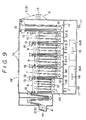
- This invention relates to an automatic processing machine used for processing a light-sensitive color photographic material. More particularly, it pertains to an automatic processing machine for a light-sensitive color photographic material constituted substantially of processing tanks for color developing, bleach-fixing and stabilizing, and having no water washing tank.
- the stabilizing solution components of the stabilizing tank which is the final processing tank is brought by the endless belt into the color developing tank which is the foremost processing tank.
- the stabilizing solution therefore accumulates in the color developing tank, thereby changing the component ratio of the color developing solution, and even accelerating deterioration (air oxidation) of the solution ultimately affecting badly the photographic performance.
- US-A-3620725 describes a processing machine which uses a roller transport system. However, according to this document it is essential to use a water washing bath between the bleach-fix bath and the stabilizer bath.
- the present invention seeks to provide an automatic processing machine which does not use tap water piping for washing with water; which avoids deterioration of photographic performance through entrainment of the stabilizing solution components to the color developing solution; which uses a reduced amount of supplementing color developing solution and stabilizing solution; which enhances safety by removing piping for discharged processing solutions which is dangerous in the working environment; which dispenses with piping construction, thereby making new installation or movement of the device very easy; which reduces environmental contamination by enabling recovery of discharged processing solution; and which necessitates no increase in the frequency of recovery of discharged processing solution even when the tank for recovery of discharged solution is made smaller.
- the present invention provides an automatic processing machine for a light-sensitive color photographic material which comprises: a plurality of processing tanks, the first tank being a color developing tank, an intermediate tank being a fixing tank and the last tank being a stabilizing tank, there being no water washing tank; at least two discharged solution recovery tanks, one of which stores discharged solution from the color developing tank and the other of which stores discharged solution from the fixing tank; and conveying means for conveying a light-sensitive material from one processing tank to the next processing tank, the conveying means comprising a short leader system, a leader system or a roller transport system, such that, when in use, stabilizing liquid components present in said stabilizing tank are not brought into said color developing tank.
- the automatic processing machine comprises at least two discharged solution recovery tanks, one of which stores the discharged solution from the color developing tank and the other of which stores a mixture of discharged solution from the fixing tank and the stabilizing tank (common use tank), or the fixing tank is a bleach-fixing tank. It is preferred not to provide a heat-exchange type cooling device with tap water in the color developing tank.
- One example of the processing steps used in the automatic processing machine of the present invention consists substantially of at least the three steps of color developing, bleach-fixing and stabilizing processing substituting for water washing.
- stabilizing solution components are prevented from being brought into the color developing tank by employment of conveying means other than an endless belt system for the light-sensitive material.
- the conveying system used in the present invention is a short leader system, or a leader or roller transport system, for example as disclosed in Japanese Provisional Patent Publications Nos. 60526/1976, 48746/1980 and 5544/1981, Japanese Utility Model Publications Nos. 27875/1980 and 39391/1980, and Japanese Provisional Utility Model Publications Nos. 90438/1982 and 205144/1982.
- a leader is provided at the head of a long light-sensitive material to be treated, and conveying the leader and/or passing said long light-sensitive material through a prescribed passage by pushing or pulling said light-sensitive material, for example using a roller
- the method in which, without providing a leader at the head of a long light-sensitive material to be treated, conveying said light-sensitive material by pushing or pulling it through a prescribed passage using a roller or the method in which, without providing a leader at the head of a long light-sensitive material to be treated, conveying said light-sensitive material by pushing or pulling it through a prescribed passage using a roller.
- a system having conveying rollers for light-sensitive materials which will not bring the stabilizing solution components filled in the stabilizing tank into the color developing solution filled in the color developing tank.
- Each processing tank should preferably be constituted so as to afford a processing solution volume of not more than 50 liters.
- the processing solution volume of not more than 50 liters represents the amount of the processing solution filled in the tank for practical processing, but when intermittent supplementing of the processing solution is carried out, it represents the amount of the processing solution when filled fully in the tank. Supplementing of each processing solution may be performed when the solution quantity becomes 95 % or less (more preferably 90 % or less) of the fully filled volume of the processing solution.
- each of the processing steps (baths) in the present invention is most preferably a single tank, but is not necessarily one tank. To increase processing speed, two or more tanks may be employed; the respective tanks may be connected to each other to permit processing solutions to flow freely into other tanks.
- the processing may also use a plurality of processing solutions having separate functions.
- the first color developing tank and the second color developing tank may be filled with different processing solutions from each other. Supplementing of the components consumed is done separately, and the tanks may also be separated from each other.
- the first stabilizing solution may contain an antifungal agent as the main component and the second stabilizing solution may contain a surfactant as the main component.
- supplemental solutions are prepared and supplemented separately.
- each processing tank should be constituted so as to afford a processing solution volume not more than 50 liters.
- each tank should have a processing solution volume of not more than 50 liters.
- each processing tank should preferably be constituted to give a processing solution volume of not more than 50 liters.
- each processing tank has a processing solution volume of preferably 40 liters or less, more preferably 30 liters or less, most preferably 20 liters or less.
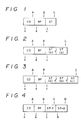
- Typical examples of the processing tank constitution in the present invention are shown in Figs. 1 through 8, in each of which, CD represents a color developing tank, BF a bleach-fixing tank, ST a stabilizing tank, BL a bleach-ing tank, Fix a fixing tank, STR a rinse stabilizing tank (see Patent Application (E) filed on May 31, 1984, by the present Applicant) and Cond a conditioning tank, respectively, and the reference numerals 1, 2, ⁇ attached as suffixes to the symbols representing tanks indicate that said tank is divided into two or more tanks with different solution compositions of the first tank, the second tank, ⁇ .
- the letters such as (a), (b) ⁇ indicate the tanks in which the processing solutions with the same composition are filled.
- the solid lines indicate that the respective tanks are substantially partitioned, the broken line and the one-directional arrowhead that the adjacent tanks are connected by a countercurrent system, and the broken line and the two-directional arrowhead that the adjacent tanks are connected to each other by the system in which the solutions in the respective systems can freely mix.
- Capital English letters A, B, C ⁇ indicate supplementing solutions for the respective tanks, while small English letters a, b, c ⁇ indicate overflow solutions from respective tanks.
- Desirable processing tank arrangements are as shown in Figs. 1 through 8.
- the embodiments of Fig. 4 and Fig. 5 are for use in color negative processing and use two kinds of stabilizing solutions, in which the stabilized solution is divided into a first stabilizing solution for desalting the bleach-fixing solution components and a second stabilizing solution which exhibits the effect of a final water draining bath to prevent droplet irregularity.
- the first stabilizing solution can be used in a very small supplementing amount to obtain the same level of desalting effect, although compactness may be lost in the case of two tanks as compared with one tank. This is because the desalting effect can be greatly improved by the countercurrent system.
- the automatic processing machine of the present invention having these processing tank arrangements gives a total amount of discharged solution of 0.95-fold or less (preferably 0.9-fold or less, particularly preferably 0.8-fold or less) of the total amount of supplemented processing solution for the respective tanks.
- Any desired means may be used for providing this.
- a sealing panel may be used to make all the processing tanks a sealed system simultaneously with provision of a ventilating fan to effect ventilation so as to promote evaporation of the processing solutions filled in the processing tanks. Evaporation may also be promoted by raising the processing solution temperatures to 30 o C or higher (preferably 33 o C or higher).
- the toal amount of discharged solution relative to the total amount of supplemented processing solution may be reduced by, for example, charging again a part or all of the discharged solution of the stabilizing solution into the stabilizing tank after regeneration or utilizing it as the processing solution for other processing tanks such as the bleach-fixing solution or fixing solution. Two or more of these means can be combined.
- the discharged solutions c and b (or c and g) in Figs. 1 through 8, and the discharged solution a are recovered and stored in separate discharged solution recovery tanks.
- the discharged solutions c and b may be recovered and stored in the same discharged solution recovery tank or alternatively in separate discharged solution recovery tanks.
- the discharged solutions d, e, f and h other than those mentioned above may be stored in the discharged solution recovery tank for discharged solution a, or in the discharged solution recovery tank for c and b (or c and g), or alternatively in an entirely different discharged solution recovery tank.
- the discharged solution recovery tank is not necessarily built in within the automatic processing machine body, but may be installed at the bottom of the body, housed in a mounting stand, kept in the vicinity of the body or kept outside the body.
- the discharged solution from the tank ST-1 nearer to the processing solution having fixing ability should preferably be mixed with the processing solution having fixing ability to be stored (in one recovery tank), but both discharged solutions from ST-1 and ST-2 may also be mixed with the processing solution having fixing ability to be stored (in one recovery tank).
- the processing solution volume ratio [CD tank] : [BF tank] : [ST tank] should preferably be [1 - 2.5] : [1] : [1 - 3].
- the processing solution volumes therein may be made approximately equal to each other.
- the stabilizing solution should preferably be supplemented rather intermittently in a large quantity on the basis of calculation of processed quantity than continuously in small quantity. For example, per processing of 70 to 120 sheets (preferably 80 to 100 sheets) of color paper E size (82 mm x 117 mm), it is preferred to supplement the solution intermittently (successively) in a large quantity, namely, 2 to 3 ml per one sheet of E size.
- any desired method may be used for calculating the amount of light-sensitive materials processed. For example, with the conveying speed of the light-sensitive materials made constant, the calculation may be made from detection and measurement of the width of the processed light-sensitive material and the processing time, whereby the processed amount can be obtained as the processed area of the light-sensitive material.
- the amount of the stabilizing solution supplemented in the present invention may be, for example, such that the ratio [CD supplemental amount] : [ST supplemental amount] is preferably [1] : [1 - 4], more preferably [1] : [1 - 3].
- the color developing processing step is the step for forming a color image, more specifically through a coupling reaction between an oxidized product of a color developing agent and a color coupler.
- This step also includes using a color photographic material containing a color developing agent therein and processing with a color developing solution or an alkali solution (activator solution) containing a color developing agent.
- the color developing agent contained in the color developing solution may be an aromatic primary amine color developing agent, including aminophenol type and p-phenylenediamine type derivatives.
- These color developing agents may be used in the form of organic acids and inorganic acids, such as chlorides, sulfates, phosphates, p-toluenesulfonates, sulfites, oxalates and benzenedisulfonates.
- These compounds may generally be used at concentrations of 0.1 g to 30 g per liter of the color developer, more preferably 1 g to 15 g per liter of the color developing solution. At a level lower than 0.1 g, insufficient color developed density is obtained.
- the processing solution temperature in the color developing tank is preferably from 10 o C to 65 o C, more preferably from 25 o C to 45 o C, to promote evaporation and developing.
- the above aminophenol type developing agent includes, for example, o-aminophenol, p-aminophenol 5-amino-2-oxy-toluene, 2-amino-3-oxy-toluene and 2-oxy-3-amino-1,4-dimethylbenzene.
- Particularly useful primary aromatic amine type color developing agents are N,N'-dialkyl-p-phenylenediamine compounds, in which the alkyl groups or phenyl groups may be either substituted or unsubstituted.
- particularly useful compounds are N,N'-dimethyl-p-phenylenediamine hydrochloride, N-methyl-p-phenylenediamine hydrochloride, N,N'-dimethyl-p-phenylenediamine hydrochloride, 2-amino-5-(N-ethyl-N-dodecyl-amino)-toluene, N-ethyl-N- ⁇ -methanesulfonamidoethyl-3-methyl-4-aminoaniline sulfate, N-ethyl-N- ⁇ -hydroxyethylaminoaniline, 4-amino-3-methyl-N,N'-diethylaniline and 4-amino-N-(2-methoxyeth
- the above color developing agents may be used either alone or in combination of two or more.
- the above color developing agent may be included within the color photographic material.
- the developing agent may be included in the form of a metal salt as disclosed in U.S. Patent No. 3,719,492; in the form of Schiff's salt as disclosed in U.S. Patent No. 3,342,559 and Research Disclosure No. 15159, 1976; in the form of a dye precursor as disclosed in Japanese Provisional Patent Publications Nos. 65429/1983 and 24137/1983; or in the form of a color developing agent precursor as disclosed in U.S. Patent No. 3,342,597.
- the color developing solution to be used in the present invention may include alkali agents usually employed in developing solutions, such as sodium hydroxide, potassium hydroxide, ammonium hydroxide, sodium carbonate, potassium carbonate, sodium sulfate, sodium metaborate or borax, and may also contain various additives, for example benzyl alcohol, alkali metal halides such as potassium bromide or potassium chloride, developing controllers such as citrazinic acid, and preservatives such as hydroxylamine or sulfites.
- alkali agents usually employed in developing solutions such as sodium hydroxide, potassium hydroxide, ammonium hydroxide, sodium carbonate, potassium carbonate, sodium sulfate, sodium metaborate or borax
- alkali agents usually employed in developing solutions, such as sodium hydroxide, potassium hydroxide, ammonium hydroxide, sodium carbonate, potassium carbonate, sodium sulfate, sodium metaborate or borax
- various additives for example benzyl alcohol, alkali metal halides such
- the pH of the color developing solution should be usually 7 or higher, preferably from 9 to 13.
- the color developing solution may also optionally incorporate antioxidants such as diethylhydroxyamine, tetronic acid, tetronimide, 2-anilinoethanol, dihydroxyacetone, aromatic secondary alcohols, hydroxamic acid, pentose, hexose or pyrogallol-1,3-dimethyl ether.
- antioxidants such as diethylhydroxyamine, tetronic acid, tetronimide, 2-anilinoethanol, dihydroxyacetone, aromatic secondary alcohols, hydroxamic acid, pentose, hexose or pyrogallol-1,3-dimethyl ether.
- chelating agents may be used in combination as sequestering agents.
- said chelating agents may include aminopolycarboxylic acids such as ethylenediaminetetraacetic acid, diethylenetriaminepentaacetic acid, organic phosphonic acids such as 1-hydroxyethylidene-1,1'-diphosphonic acid, aminopolyphosphonic acids such as aminotri(methylenephosphoric acid) or ethylenediaminetetraphosphoric acid, oxycarboxylic acids such as citric acid or gluconic acid, phosphonocarboxylic acids such as 2-phosphonobutane-1,2,4-tricarboxylic acid, polyphosphoric acids such as tripolyphosphoric acid or hexametaphosphoric acid, and polyhydroxy compounds.
- aminopolycarboxylic acids such as ethylenediaminetetraacetic acid, diethylenetriaminepentaacetic acid, organic phosphonic acids such as 1-hydroxyethylidene-1,1'-diphosphonic acid, aminopoly
- the bleach-fixing step refers to the step in which the metallic silver formed by development is oxidized into a silver halide, followed by formation of a water-soluble complex simultaneously with color formation of the non-color formed portion of the color forming agent.
- the bleaching agent used in the bleach-fixing solution is preferably a metal complex of an organic acid.
- the metal ion is, for example, iron, cobalt or copper, and is coordinated with an organic acid such as aminopolycarboxylic acid, oxalic acid or citric acid.
- the most preferred organic acids are polycarboxylic acids or aminopolycarboxylic acids. These polycarboxylic acids or aminopolycarboxylic acids may be alkali metal salts, ammonium salts or water-soluble amine salts. Examples of these compounds are:
- bleaching agents may be used in amounts of from 5 to 450 g/l, more preferably from 20 to 250 g/l.
- the bleach-fixing solution may contain a silver halide fixing agent in addition to the bleaching agent as described above, and also optionally contain a sulfite as a preservative. It is also possible to use a bleach-fixing solution comprising a composition in which an ethylenediaminetetraacetic acid iron (III) complex bleaching agent and a small amount of a halide such as ammonium bromide which differ from the above-mentioned silver halide fixing agent are added, or a bleach-fixing solution in which a large amount of a silver halide such as ammonium bromide has been added, and furthermore a special bleach-fixing solution comprising a combination of an ethylenediaminetetraacetic iron (III) complex and a large amount of a halide such as ammonium bromides.
- halides there may, for example, be employed, other than ammonium bromide, hydrochloric acid, hydrobromic acid, lithium bromide, sodium bromide, potassium bromide, sodium iodide, potassium iodide or ammonium iodide.
- the silver halide fixing agent contained in the bleach-fixing solution there may be employed compounds capable of forming water-soluble complexes by reaction with silver halide which employed in a usual fixing process, as typically exemplified by thiosulfates such as potassium thiosulfate, sodium thiosulfate or ammonium thiosulfate, thiocyanates such as potassium thiocyanate, sodium thiocyanate or ammonium thiocyanate, thiourea and thioether.
- thiosulfates such as potassium thiosulfate, sodium thiosulfate or ammonium thiosulfate
- thiocyanates such as potassium thiocyanate, sodium thiocyanate or ammonium thiocyanate
- thiourea and thioether thioether.
- the bleach-fixing solution may also contain pH buffering agents such as boric acid, borax, sodium hydroxide, potassium hydroxide, sodium carbonate, potassium carbonate, sodium bicarbonate, potassium bicarbonate, acetic acid, sodium acetate or ammonium hydroxide, either alone or in a combination of two or more.
- pH buffering agents such as boric acid, borax, sodium hydroxide, potassium hydroxide, sodium carbonate, potassium carbonate, sodium bicarbonate, potassium bicarbonate, acetic acid, sodium acetate or ammonium hydroxide, either alone or in a combination of two or more.
- Various fluorescent whitening agents, deforming agents or surfactants may also be incorporated.
- preservatives such as hydroxylamine, hydrazine or bisulfite adducts of aldehyde compounds, organic chelating agents such as aminopolycarboxylic acids, stabilizers such as nitro alcohol or nitrates, or organic solvents such as methanol, dimethylsulfoamide or dimethylsulfoxide.
- the bleach-fixing solution is used at a pH of 4.0 or higher, but generally at a pH of 5.0 to 9.5, desirably 6.0 to 8.5, most preferably 6.5 to 8.5.
- the processing temperature may be 80 o C or lower, and lower by 3 o C or more, preferably 5 o C or more, than the processing temperature in the color developing tank, but desirably at 35 o C or lower, while suppressing evaporation.
- the stabilizing processing used in the present invention is a substitute for washing with water, such as the image stabilizing processing disclosed in the above-mentioned Japanese Provisional Patent Publication No. 134636/1983 and in Japanese Provisional Patent Publication No. 126533/1984 and others, which obviate water washing processing. Accordingly, the processing bath is not necessarily called a stabilizing processing bath.
- the stabilizing solutions may also have the function of processing for stabilization of color images and the function of a water draining bath for prevention of contamination such as water washing irregularities. Otherwise, there may also be included coloring controlling solutions for coloring the color image and antistatic solutions containing antistatic agents in these stabilizing solution.
- coloring controlling solutions for coloring the color image and antistatic solutions containing antistatic agents in these stabilizing solution.
- the components incorporated in the stabilizing solution may include chelating agents having a chelate stabilization coefficient with iron ions of 6 or higher (particularly 8 or higher).
- chelating agents may include organic carboxylic acid chelating agents, organic phosphoric acid chelating agents, polyhydroxylic compounds and inorganic phosphoric acid chelating agents.
- preferred chelating agents are ethylenediamine-di-ortho-hydroxyphenylacetic acid, nitrilotriacetic acid, hydroxyethylenediaminetriacetic acid, diethylenetriaminepentaacetic acid, hydroxyethyliminediacetic acid, diaminopropanoltetraacetic acid, ethylenediaminetetrakis-methylenephosphonic acid, nitrilotrimethylenephosphonic acid, 1-hydroxyethylidene-1,1'-diphosphonic acid, 1,1'-diphosphonoethane-2-carboxylic acid, 2-phosphonobutane-1,2,4-tricarboxylic acid, 1-hydroxy-1-phosphonopropane-1,2,3-tricarboxylic acid, catechol-3,5-disulfonic acid, sodium pyrophosphate, sodium tetrapolyphosphoric acid and sodium hexametaphosphoric acid.
- These compounds may be used at concentrations of 0.1 g to 10 g per liter of the stabilizing solution, more preferably 0.5 g to 5 g per liter of the stabilizing solution.
- ammonium compounds include ammonium compounds. These can be ammonium salts of various inorganic compounds, including ammonium hydroxide, ammonium bromide, ammonium carbonate, ammonium chloride, ammonium hypophosphite, ammonium phosphate, ammonium phosphite, ammonium fluoride, acidic ammonium fluoride, ammonium fluoroborate, ammonium arsenate, ammonium hydrogen carbonate, ammonium hydrogen fluoride, ammonium hydrogen sulfate, ammonium sulfate, ammonium iodide, ammonium nitrate, ammonium pentaborate, ammonium acetate, ammonium adipate, ammonium taurinetricarboxylate, ammonium benzoate, ammonium carbamate, ammonium citrate, ammonium diethyldithiocarbamate, ammonium formate, ammonium hydrogen malate, ammonium
- ammonium compounds may be added in amounts of from 0.05 to 100 g, preferably from 0.1 to 20 g, per liter of the stabilizing solution.
- desirable compounds to be added in the stabilizing solution may include pH controllers such as acetic acid, sulfuric acid, hydrochoric acid, nitric acid, sulfanilic acid, potassium hydroxide, sodium hydroxide and ammonium hydroxide; anti-fungal agents such as sodium benzoate, butyl hydroxy benzoate, antibiotics, dehydroacetic acid, potassium sorbate, thiapentazole and o-phenylphenol; preservatives such as 5-chloro-2-methyl-4-isothiazoline- 3-one, 2-octyl-4-isothiazoline-3-one, 1,2-benzisothiazoline-3-one and water-soluble metal salts; dispersants such as ethylene glycol, polyethylene glycol and polyvinyl pyrrolidone (e.g. PVP K-15, Rubiscol K-17); film hardeners such as formalin; and fluorescent whitening agents.
- pH controllers such as acetic acid, sulfuric acid, hydrochoric acid, ni
- ammonium compounds discribed in Japanese Provisional Patent Publication No. 184345/1984. These act to control the pH in the image coating to weakly acidic as optimal for storage.
- the compound preferably used together with the ammonium compound is an acid, more preferably sulfuric acid or hydrochloric acid.
- the pH of the stabilizing solution should desirably be controlled to 0.1 to 10, preferably 2 to 9, more preferably 4 to 8.5.
- the processing temperature during stabilizing processing is preferably from 15 o C to 60 o C, and lower by 3 o C or more, preferably 5 o C or more, than that in the color developing tank, more preferably from 20 o C to 38 o C.
- the processing time should preferably be as short as possible from the viewpoint of rapid processing, but is generally from 20 seconds to 10 minutes, most preferably from 20 seconds to 3 minutes.
- the tanks in the preceding stages should desirably be processed within a short period of time, and those in the later stages for a longer time. Particularly, it is desirable to process successively such that each tank has a processing time longer by 20 % to 50 % than that of the preceding tank.
- the stabilizing processing is performed directly subsequent to the bleach-fixing processing step without passing through a water washing step, and a silver recovery step may be provided for a short time for recovery of silver or a rinsing step with pooled water between the bleach-fixing tank and the stabilizing tank. Also, after the stabilizing processing, there may be provided a water draining bath containing a surfactant, but preferably no such silver recovery tank, rinsing and water draining bath should be provided. These additive processing can be applied by spraying or coating.
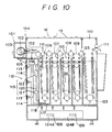
- Processing may be conducted while permitting said stabilizing solution to be in contact with ion-exchange resins.
- a part of the treated solution can be used as said stabilizing solution.
- the stabilizing solution is taken out from the stabilizing tank, permitted to contact ion-exchange resins separately from the stabilizing tank by the column method or the mixing method, and thereafter a part thereof is charged back into the stabilizing tank.
- charging into the stabilizing tank may be done as the supplemental solution, it is preferred to recycle the solution after ion-exchange treatment through a circulation system independently of the supplementing system.
- the stabilized discharged solution thus regenerated can also be charged into the bleach-fixing tank.
- contact with ion-exchange resins may be performed in any tank in the case of a multi-tank stabilizing bath, it is preferred to perform the treatment in the tank immediately after the bleach-fixing tank.
- This treatment should preferably be conducted in two or more tanks, particularly preferably in all of the tanks.
- a preferred embodiment in the case of the stabilizing bath having one tank is to effect contact with ion-exchange resins placed in a resin column connected to the stabilizing tank.
- a preferred embodiment in the case of the stabilizing bath having two tanks is to effect contact with ion-exchange resins placed in a resin column or a filter case which is connected directly to the first tank immediately after the bleach-fixing processing, more preferably contact being effected similarly in the second tank.
- a preferred embodiment in the case of the stabilizing bath having three or more tanks is to effect contact in the first tank immediately after the bleach-fixing processing similarly as described above, more preferably contact being effected similarly in respective columns with ion-exchange resins columns or filter cases directly connected thereto.
- the stabilized solution it is most preferred to permit the stabilized solution to contact with ion-exchange resins directly connected to the stabilizing tank.
- the stabilizing solution it is also possible to permit the stabilizing solution to be taken out from the stabilizing tank by forcibly increasing overflow or the amount supplemented to contact ion-exchange resins, followed by charging back into the stabilizing bath.
- the stabilizing bath consists of one tank, the stabilizing solution taken out is permitted to contact ion-exchange resins by use of a resin column, and then the stabilized solution after contact is charged back into the stabilizing tank.
- the stabilizing solution after contact should preferably have further stabilizing components added.
- the stabilizing bath consists of two or more tanks
- stabilizing solution components should be added into the solution to be returned. While it is possible to use the stabilizing solution after contact with ion-exchange resins as the supplemental solution, it is desirable in this case to add stabilizing solution components thereto.
- the above ion-exchange resins should preferably be brought into contact with the bleach-fixing solution after contact with the stabilizing solution, followed by regeneration.
- silver recovery may be possible by regeneration of resins.
- Electrodialytic treatment (see Japanese Patent Application No. 96352/1984) or reverse osmosis treatment (see Japanese Patent Application No. 96350/1984) may also be applicable.
- a conditioning tank may also be provided after the color developing processing as described above, said conditioning tank being employed for stopping development to promote bleaching reaction and serving to preventing entrainment of developing solution into the bleach-fixing solution to reduce its adverse effect.
- a bleaching accelerator and a buffer agent may be contained.
- said bleaching accelerator there may generally be employed organic sulfur compounds, including mercapto compounds and thio compounds.
- Acid or alkali agents such as acetic acid, citric acid, succinic acid, sulfuric acid and sodium hydroxide may be used for controlling the pH of the conditioner.
- These bleaching accelerators or buffer agents may be added in amounts of 0.001 g to 100 g per liter of the conditioner.
- chelating agents may also be added.
- This conditioning tank is also preferred to be constituted so as to afford a processing solution volume of not more than 50 liters.
- the stabilizing solution for negative materials is described for use when the light-sensitive material to be processed is a negative material
- an aldehyde derivative is added.
- the aforesaid aldehyde derivative is an aldehyde compound or an aldehyde adduct represented by the formulae (1), (2) or (3) shown below, and at least one selected from among these is used.
- formula (1) R1-CHO
- R1 represents a hydrogen atom, an alkyl group having 1 to 5 carbon atoms, a formyl group, an acetyl group, an acetonyl group, a hydroxy group, or an alkyl group having 1 to 5 carbon atoms which may be substituted, for example with an alkoxy group, a formyl group, an amino group, a hydroxyimino group or a halogen atom;
- R2 represents a hydrogen atom or an alkyl group having 1 to 5 carbon atoms;
- R3 an alkyl group having 1 to 5 carbon atoms which may be substituted;
- M an alkali metal;
- R4 and R5 each a hydrogen atom or an alkyl group having 1 to 5 carbon atoms which may be substituted; and
- n an integer of 0 to 4.
- the compounds represented by the above formulae should preferably be used in amounts of from 0.01 to 50 g per liter of the stabilizing solution, more preferably from 0.05 to 20 g, to obtain good results.
- additives can be added, if desired.
- droplet irregularity preventatives such as siloxane derivatives
- pH controllers such as boric acid, citric acid, phosphoric acid, acetic acid, sodium hydroxide, sodium acetate and potassium citrate
- film hardeners such as potassium alum and chromium alum
- organic solvents such as methanol, ethanol and dimethyl sulfoxide
- humidity controllers such as ethylene glycol and polyethylene glycol
- other tone controllers such as siloxane derivatives, a pH controllers such as boric acid, citric acid, phosphoric acid, acetic acid, sodium hydroxide, sodium acetate and potassium citrate
- film hardeners such as potassium alum and chromium alum
- organic solvents such as methanol, ethanol and dimethyl sulfoxide
- humidity controllers such as ethylene glycol and polyethylene glycol
- other tone controllers such as siloxane derivatives
- the stabilizing solution for negative materials may also be divided into two or more sections similarly as the stabilizing solution as described above in order to elongate the countercurrent flow pathway. Preparation of the supplementing solution, the amount to be supplemented and the processing temperature are the same as in the stabilizing solution as described above.
- a stilbene type fluorescent whitening agent can be used in the color developing solution for color paper or the stabilizing solution; such fluorescent whitening agents including the compounds represented by the formula (4) shown below:
- fluorescent whitening agents including the compounds represented by the formula (4) shown below:
- Y1 and Y2 each represents a group of formula: or a group of formula:
- R6, R7 and R8 each represents a hydroxyl group, a halogen atom such as chlorine or bromine, a morpholino group, a substituted or unsubstituted alkoxy group (e.g. methoxy, ethoxy or methoxyethoxy), a substituted or unsubstituted aryloxy group (e.g. phenoxy or p-sulfophenoxy), a substituted or unsubstituted alkyl group (e.g. methyl or ethyl), a substituted or unsubstituted aryl group (e.g.
- phenyl or methoxyphenyl an amino group or a substituted or unsubstituted alkylamino group (e.g. methylamino, ethylamino, propylamino, dimethylamino, cyclohexylamino, ⁇ -hydroxyethylamino, di( ⁇ -hydroxyethyl)amino, ⁇ -sulfoethylamino, N-( ⁇ -sulfoethyl)-N-methylamino or N-( ⁇ -hydroxyethyl)-N-methylamino).
- alkylamino group e.g. methylamino, ethylamino, propylamino, dimethylamino, cyclohexylamino, ⁇ -hydroxyethylamino, di( ⁇ -hydroxyethyl)amino, ⁇ -sulfoethylamino, N-( ⁇ -sulfoethyl
- the fluorescent whitening agent represented by formula (4) may be used in an amount of from 0.2 to 10 g, preferably from 0.5 to 3.0 g, per liter of the stabilizing solution.
- Fig. 9 is a cross-sectional view of the essential part of the automatic processing machine using the tank constitution shown in Example
- a feeding section 4 for feeding an exposed but undeveloped color negative film (negative light-sensitive material) 2 or a color paper (positive light-sensitive material) 3, and, on the rear, a take-out section 5 for taking out the processed light-sensitive materials 2 and 3.
- a color developing tank 6 Between the feeding section 4 and the take-out section 5, namely within the processing machine body, there are disposed successively adjacent to each other a color developing tank 6, a bleach-fixing tank 7, a first stabilizing tank 8, a second stabilizing tank 9, a third stabilizing tank 10 and a drying section 11.
- a conveying guide is provided so as to convey the light-sensitive material 2 or 3.
- 13 shows the wind-up section for the light-sensitive material 2 or 3.
- a holding section 14 at which is set the exposed but undeveloped light-sensitive material 2 or 3.
- the above-mentioned color developing tank 6, the bleach-fixing tank 7, the first stabilizing tank 8, the second stabilizing tank 9 and the third stabilizing tank 10 are constituted as shown in Fig. 3. That is, the color developing tank 6 is filled with the color developing solution as mentioned above, and the respective processing tanks 7, 8, 9 and 10 which are disposed at the next steps of the color developing tank 6 are also filled with the respective processing solutions as described above. Supplemental solutions for the respective tanks may be fed as shown in Fig. 3.
- the first, the second and the third stabilizing tanks 8, 9 and 10 have different liquid surface levels to each other so that overflow occurs according to the counter-current system from the third tank to the second tank, and from the second tank to the first tank.
- the overflow solution from the third tank 10 is discharged out of the tank from the first tank 8.
- the stabilizing tank may be constituted of either one tank or two tanks, but the multi-tanks counter-current system has the advantage of high stabilizing efficiency with a small amount of supplmenting solution.
- 15 shows a blade or squeezing section which uses, for example, a pyramid type blade plate, which prevents effectively bringing of the solution from the preceding tank to the next tank.
- 16A and 16B show discharged solution recovery tanks which are provided detachably at the bottom portion of the developing body 1, the discharged solution recovery tank 16A containing the overflow discharged solution from the color developing tank 6, while the discharged solution recovery tank 16B containing the overflow discharged solutions from the bleach-fixing tank 7 and the first stabilizing tank 8.
- the discharged solution recovery tanks 16A and 16B may be connected to the pipes for overflow discharge solutions in any desired manner, for example to recover solutions by gravity, but it is preferred to accomodate the arrangement so that the discharged solutions from said overflow discharged solution pipes will not drip by, for example, the action of valves, when the discharged solution recovery tanks 16A and 16B are withdrawn for exchange.
- the discharged solution recovery tanks 16A and 16B may also have, in addition to openings for receiving the above overflow discharged solution pipes, openings for silver recovery or other purposes (these openings are equipped with lids).
- the volumes of the discharged solution recovery tanks 16A and 16B may preferably be such that only one recovery per week is required when running the automatic developing device every day, but there is no particular limitation in this respect. It is also possible to provide a detecting section and an alarm or display section, which can detect (through detection of weight, liquid level or the position of the discharged solution recovery tank) and sound buzzer or alarm, or make a display, when a certain amount of solution is stored.
- a detecting section and an alarm or display section which can detect (through detection of weight, liquid level or the position of the discharged solution recovery tank) and sound buzzer or alarm, or make a display, when a certain amount of solution is stored.
- 17 shows a caster and 18 a knob for the discharged solution recovery tank.
- 18' is a large lid for making the respective processing tanks 6 - 10 a sealed system
- 19 shows a small lid provided above each of the tanks 6 - 10 of said large scale lid 18'.
- 20 is a means for conveying light-sensitive materials according to the short leader system, or the leader or roller transport system.
- processing solution volume in the CD tank being 25 liters
- BF tank 15 liters and in each of ST-1 - ST-3 15 liters 100 m on average per day of E-size roll paper was processed.
- amounts of processing solutions supplemented were as follows: per 100 cm2 of color paper, CD supplemental amount was 2 ml, BF supplemental amount 1 ml and ST supplemental amount 2 ml.
- the color developing solution in the CD tank was sampled and the concentration of ferric salts of aminopolycarboxylic acid was measured to find that it was only 1 ppm.
- the endless belt system was used in place of the above roller transport system, and the amount of each of CD and ST supplemented increased to 3 ml, with the BF amount supplemented being unchanged. Nevertheless, the concentration of ferric salts of aminopolycarboxyic acids was as much as 10 ppm measured as iron ions, and tar was generated in the color developing solution.
- the above soluble silver salts may be recovered according to the above methods after recovery of the overflow solution of the processed solution, and the remaining solution may be either disposed of as waste solution or used as the supplemental solution or the tank processing solution with addition of a regenerating agent.
- Fig. 10 is a cross-sectional view of the essential part the automatic processing machine for color negative film according to the present invention in which the numerals in commen with those used in Fig. 9 have the same meaning.
- 101 is a section for mounting a magazine housing a roll having a color negative film wound up connected thereto, and is provided on the side wall of the automatic processing machine body 104.
- the color negative film 102 in the film magazine mounted on the mounting section 101 enters through the body inlet section 105 into the body 104, is subjected automatically to developing processing through the color developing tank 106, the bleach-fixing tank 107, the first stabilizing tank 108 and the second stabilizing tank 109, then dried in the drying section 110 (having an openable lid), taken out from the body outlet 111, followed by other steps such as cutting, to be made into a product.
- the color developing tank 106, the bleach-fixing tank 107, the first stabilizing tank 108 and the second stabilizing tank 109 are arranged successively in parallel as shown in the Figure. Rollers for conveying negative films are provided in respective tanks and desired processings are performed while dipping the negative film 102 in solutions. On the respective tanks 106 - 109 are provided openable lids 19, etc. for prevention of penetration of dust.
- the automatic processing machine of this example is provided with a cooling chamber 112 adjacent to the color developing tank 106.
- Said cooling chamber 112 is provided at its outer wall with a fan 113 with an appropriate number of through-holes 114 for introduction of outer air.
- Said cooling chamber 112 also functions as the controlling system instrument chamber, in which a controlling section 116 is housed.
- Said controlling section 116 performs temperature control for heating by controlling ON-OFF of a large capacity electric heater 117 and a small capacity electric heater 118 by the input signal of the liquid temperature in the color developing tank detected by a temperature sensor 115, and also performs temperature control for cooling by controlling ON-OFF of the fan 113.
- automatic processing machines of the prior art had only the large capacity electric heater 117 as the heating system, and employed a cooling means using water as the cooling medium with provision of a tap water pipeline at the hose provided near the bottom of the color developing tank 106.
- a cooling means using water as the cooling medium
- a tap water pipeline at the hose provided near the bottom of the color developing tank 106.
- the volume of the color developing tank 106 is 20 liters
- about 1000 liters of tap water is required for maintaining the color developing tank 106 at 38 o C during running (about 12 hours).
- the liquid temperature in the color developing tank 106 could be maintained at a temperature range of 38 o C ⁇ 0.15 o C during running time (about 12 hours).
- the cooling water as employed in the prior art example can be omitted. No tap water piping is also required.
- the heating system in said example during start-up, the liquid tempeature was elevated up to 38 o C by means of the large capacity electric heater 117 (and the small capacity electric heater 118), and the liquid temperature control performed by means of the small capacity electric heater 118 during running processing.
- the three fans 113 were continued to be actuated during running.
- 119 is a liquid circulating stirring apparatus having the controlling system instrument chamber functioning also as the cooling chamber 112 housed therein, and comprises a liquid delivering pump 121 and a filter for liquid cleaning 122 in the course of the passage 120 connecting the upper part and the lower part of the color developing tank 106.
- the position at which the fan 113 is mounted is not limited to that of this example, but it may also, for example, be on the ceiling.
- 125 shows a blade or squeezing section such as a pyramid type blade plate, which prevents effectively bringing of liquid from the previous bath into the next bath.
- 123 shows a drying section and 126 a knob of the discharged solution recovery tank.
- 124A and 124B show discharged solution recovery tanks, and into one of the tanks 124A, the color developing solution and the second stabilizing solution are permitted to flow, while the bleach-fixing solution and the first stabilizing solution into the other tank 124 B.
- the first stabilizing tank 108 of this example contains a stabilizing solution which stabilizes images and contains an anti-fungal agent, which is provided primarily for the purpose of a desalting bath.
- the second stabilizing tank 109 is a processing bath comprising a surfactant and formalin, which is provided for the purpose of preventing droplet irregularity contamination.
- a solution containing only a surfactant there may also be employed.
- an automatic processing machine for light-sensitive color photographic material having a color developing tank as the foremost tank of the processing tanks, an intermediate tank being a fixing tank, a stabilizing tank as the last tank of the processing tanks and at least two discharged solution recovery tanks, one of which stores discharged solution from the color developing tank and the other of which stores discharged solution from the fixing tank, has a system for conveying light-sensitive materials without bringing the stabilizing solution components filled in the above stabilizing tank into the color developing solution filled in the above color developing tank, this system being a short leader system, a leader system or a roller transport system.
Landscapes
- Physics & Mathematics (AREA)
- General Physics & Mathematics (AREA)
- Silver Salt Photography Or Processing Solution Therefor (AREA)
- Photographic Processing Devices Using Wet Methods (AREA)
Claims (5)
- Automatisches Entwicklungsgerät für ein lichtempfindliches farbfotografisches Aufzeichnungsmaterial, umfassend:
eine Mehrzahl von Verarbeitungstanks, wobei der erste Tank ein Farbentwicklungstank ist, ein Zwischentank ein Fixiertank ist und der letzte Tank ein Stabilisierungstank ist, wobei kein Waschwassertank vorhanden ist;
mindestens zwei Abfangtanks für abgelassene Lösung, von denen der eine abgelassenen Lösung aus dem Farbentwicklungstank speichert und der andere abgelassenen Lösung aus dem Fixiertank speichert; und
Fördermittel zum Befördern eines lichtempfindlichen Materials aus einem Verarbeitungstank zum nächsten Verarbeitungstank, wobei das Fördermittel ein Kurzvorspannstück-System, ein Vorspannstück-System oder ein Rollen-Transportsystem umfaßt, derart, daß beim Gebrauch stabilisierende flüssige Komponenten, die in dem Stabilisierungstank anwesend sind, nicht in den Farbentwicklungstank hineingebracht werden. - Gerät nach Anspruch 1, worin der Fixiertank ein Bleich-Fixiertank ist.
- Gerät nach Anspruch 2, worin das Volumenverhältnis des Farbentwicklungstanks, des Bleich-Fixiertanks und des Stabilisierungstanks 1 bis 2,5 : 1 : 1 bis 3 ist.
- Gerät nach irgendeinem der vorangehenden Ansprüche, worin jeder Verarbeitungstank aus einem oder zwei oder mehr geteilten Tanks aufgebaut ist.
- Gerät nach Anspruch 4, worin die geteilten Tanks ein Volumen von 50 Liter oder weniger aufweisen.
Applications Claiming Priority (2)
| Application Number | Priority Date | Filing Date | Title |
|---|---|---|---|
| JP59124637A JPS614059A (ja) | 1984-06-18 | 1984-06-18 | カラ−写真感光材料用自動現像機 |
| JP124637/84 | 1984-06-18 |
Publications (3)
| Publication Number | Publication Date |
|---|---|
| EP0165805A2 EP0165805A2 (de) | 1985-12-27 |
| EP0165805A3 EP0165805A3 (en) | 1987-06-03 |
| EP0165805B1 true EP0165805B1 (de) | 1993-01-13 |
Family
ID=14890338
Family Applications (1)
| Application Number | Title | Priority Date | Filing Date |
|---|---|---|---|
| EP85304353A Expired - Lifetime EP0165805B1 (de) | 1984-06-18 | 1985-06-18 | Automatisches Entwicklungsgerät für lichtempfindliches farbphotographisches Material |
Country Status (6)
| Country | Link |
|---|---|
| US (2) | US4705377A (de) |
| EP (1) | EP0165805B1 (de) |
| JP (1) | JPS614059A (de) |
| AU (1) | AU588531B2 (de) |
| CA (1) | CA1254428A (de) |
| DE (2) | DE3586973D1 (de) |
Families Citing this family (14)
| Publication number | Priority date | Publication date | Assignee | Title |
|---|---|---|---|---|
| JPH0442842Y2 (de) * | 1987-12-19 | 1992-10-09 | ||
| JPH01211760A (ja) * | 1988-02-19 | 1989-08-24 | Konica Corp | 自動現像機 |
| US4910546A (en) * | 1988-04-27 | 1990-03-20 | Fuji Photo Film Co., Ltd. | Film processing device |
| JPH01302250A (ja) * | 1988-05-30 | 1989-12-06 | Minolta Camera Co Ltd | 現像機 |
| US4980714A (en) * | 1989-04-19 | 1990-12-25 | Fuji Photo Film Co., Ltd. | Photosensitive material processing apparatus |
| US5168297A (en) * | 1989-08-26 | 1992-12-01 | Agfa Gevaert Aktiengesellschaft | Countercurrent final treatment system |
| JP2623156B2 (ja) * | 1990-04-26 | 1997-06-25 | 富士写真フイルム株式会社 | 感光性平版印刷版処理装置用補充液補充装置 |
| US5301838A (en) * | 1991-01-23 | 1994-04-12 | Continental Pet Technologies, Inc. | Multilayer bottle with separable inner layer and method for forming same |
| DE69214248T2 (de) * | 1991-05-01 | 1997-04-30 | Konishiroku Photo Ind | Automatisches entwicklungsgerät für lichtempfindlichen träger auf silberhalogenidbasis |
| US5400105A (en) * | 1992-10-30 | 1995-03-21 | Konica Corporation | Automatic processing machine for silver halide photographic light-sensitive materials |
| DE4311642C2 (de) * | 1993-04-08 | 1996-05-30 | Agfa Gevaert Ag | Vorrichtung zum Entwickeln blattförmiger fotografischer Schichtträger |
| GB9417319D0 (en) * | 1994-08-27 | 1994-10-19 | Kodak Ltd | Improvements in or relating to photographic processing |
| US5778274A (en) * | 1996-09-30 | 1998-07-07 | Eastman Kodak Company | Photographic processor and method of operation |
| US6436344B1 (en) * | 1999-11-02 | 2002-08-20 | American National Red Cross | Method of inactivating pathogens |
Family Cites Families (19)
| Publication number | Priority date | Publication date | Assignee | Title |
|---|---|---|---|---|
| US3388653A (en) * | 1965-07-01 | 1968-06-18 | William C. Mayfield | Film processing apparatus |
| US3620725A (en) * | 1969-01-23 | 1971-11-16 | Technology Inc | Rapid photographic development system |
| BE795122A (nl) * | 1972-02-21 | 1973-08-08 | Agfa Gevaert Nv | Behandelingsapparaat voor fotografisch materiaal |
| DE2361151B2 (de) * | 1973-12-07 | 1980-05-08 | Agfa-Gevaert Ag, 5090 Leverkusen | Verfahren zur Aufbereitung der Abiaufflüssigkeiten bei fotografischen Entwicklungsprozessen und Vorrichtung zur Durchführung des Verfahrens |
| DE2361150B2 (de) * | 1973-12-07 | 1980-12-11 | Agfa-Gevaert Ag, 5090 Leverkusen | Fotografisches Gerät zur Naßbehandlung fotografischer Schichtträger |
| US4060873A (en) * | 1975-06-20 | 1977-12-06 | Agfa-Gevaert Aktiengesellschaft | Apparatus for removing liquids from moving strips of photographic material or the like |
| JPS5216286U (de) * | 1975-07-23 | 1977-02-04 | ||
| JPS5240435A (en) * | 1975-09-26 | 1977-03-29 | Kawasaki Steel Co | Manufacture of composite metals block |
| US4174901A (en) * | 1977-06-03 | 1979-11-20 | Dainippon Screen Seizo Kabushiki Kaisha | Film squeegee mechanism of automatic film developing apparatus |
| JPS606263B2 (ja) * | 1978-09-05 | 1985-02-16 | ノ−リツ鋼機株式会社 | シ−ト状長尺フイルムの蛇行防止装置付移送機構 |
| US4239367A (en) * | 1979-03-14 | 1980-12-16 | Hope Henry F | Continuous-band web transport |
| JPS5635136A (en) * | 1979-08-30 | 1981-04-07 | Canon Inc | Film processing unit |
| JPS578543A (en) * | 1980-06-18 | 1982-01-16 | Konishiroku Photo Ind Co Ltd | Processing method for color photographic sensitive silver halide material |
| JPS5814834A (ja) * | 1981-07-21 | 1983-01-27 | Konishiroku Photo Ind Co Ltd | ハロゲン化銀カラ−写真感光材料の安定化処理方法 |
| JPS5818630A (ja) * | 1981-07-28 | 1983-02-03 | Konishiroku Photo Ind Co Ltd | ハロゲン化銀カラ−写真感光材料の処理方法 |
| JPS58105150A (ja) * | 1981-12-17 | 1983-06-22 | Fuji Photo Film Co Ltd | カラ−写真処理装置 |
| US4429982A (en) * | 1982-04-08 | 1984-02-07 | Pluribus Products, Inc. | Apparatus and method for processing stabilization photographic paper |
| US4502772A (en) * | 1982-05-17 | 1985-03-05 | Noritsu Kenkyu Center Co. Ltd. | Apparatus for treating disc films |
| DE3402506A1 (de) * | 1983-01-25 | 1984-08-09 | Fuji Photo Film Co., Ltd., Minami Ashigara, Kanagawa | Verfahren und vorrichtung zur behandlung von strahlenempfindlichem material |
-
1984
- 1984-06-18 JP JP59124637A patent/JPS614059A/ja active Pending
-
1985
- 1985-06-12 US US06/743,958 patent/US4705377A/en not_active Expired - Lifetime
- 1985-06-17 AU AU43739/85A patent/AU588531B2/en not_active Ceased
- 1985-06-17 CA CA000484181A patent/CA1254428A/en not_active Expired
- 1985-06-18 DE DE8585304353A patent/DE3586973D1/de not_active Expired - Lifetime
- 1985-06-18 DE DE85304353T patent/DE3586973T4/de not_active Expired - Lifetime
- 1985-06-18 EP EP85304353A patent/EP0165805B1/de not_active Expired - Lifetime
-
1987
- 1987-11-06 US US07/118,741 patent/US4780737A/en not_active Expired - Lifetime
Also Published As
| Publication number | Publication date |
|---|---|
| JPS614059A (ja) | 1986-01-09 |
| US4780737A (en) | 1988-10-25 |
| CA1254428A (en) | 1989-05-23 |
| EP0165805A3 (en) | 1987-06-03 |
| AU588531B2 (en) | 1989-09-21 |
| EP0165805A2 (de) | 1985-12-27 |
| DE3586973D1 (de) | 1993-02-25 |
| AU4373985A (en) | 1986-01-02 |
| DE3586973T4 (de) | 1993-11-11 |
| DE3586973T2 (de) | 1993-06-17 |
| US4705377A (en) | 1987-11-10 |
Similar Documents
| Publication | Publication Date | Title |
|---|---|---|
| EP0165805B1 (de) | Automatisches Entwicklungsgerät für lichtempfindliches farbphotographisches Material | |
| US4829330A (en) | Automatic image developing apparatus for silver halide photographic photosensitive material | |
| US5066570A (en) | Wet processing of silver halide photosensitive material | |
| US5108878A (en) | Method for processing silver halide photosensitive material | |
| US4797352A (en) | Method of processing a silver halide photographic light-sensitive material | |
| US4876180A (en) | Method of and apparatus for processing silver halide-containing photosensitive material for color photography | |
| US4800408A (en) | Photographic material developing and processing apparatus | |
| JPH055104B2 (de) | ||
| JPS60263941A (ja) | カラ−写真感光材料用自動現像機 | |
| JPS60233651A (ja) | カラ−写真感光材料用自動現像機 | |
| JPS614057A (ja) | カラ−写真感光材料用自動現像機 | |
| JPS60252350A (ja) | ヨウ臭化銀含有撮影用感光材料の処理方法 | |
| JPS614058A (ja) | カラ−写真感光材料用自動現像機 | |
| JPH0664323B2 (ja) | 自動現像装置の清浄方法 | |
| JPS612153A (ja) | カラ−写真感光材料用自動現像機 | |
| JPS614056A (ja) | カラ−写真感光材料用自動現像機における補充液の補充方法 | |
| JPS60254134A (ja) | カラ−写真感光材料用自動現像機 | |
| JPS612154A (ja) | カラ−写真感光材料用自動現像機 | |
| JP4060067B2 (ja) | ハロゲン化銀カラー写真感光材料の処理剤及び処理方法 | |
| JPH0723955B2 (ja) | ハロゲン化銀カラ−写真感光材料の処理方法 | |
| US5702874A (en) | Method of processing photographic silver halide materials | |
| JP2741549B2 (ja) | 感光材料処理装置 | |
| JPS614049A (ja) | ハロゲン化銀カラー写真感光材料の処理廃液からの銀回収方法 | |
| JPS60263940A (ja) | ハロゲン化銀写真感光材料の処理方法 | |
| JPS61112148A (ja) | カラ−写真感光材料用自動現像機 |
Legal Events
| Date | Code | Title | Description |
|---|---|---|---|
| PUAI | Public reference made under article 153(3) epc to a published international application that has entered the european phase |
Free format text: ORIGINAL CODE: 0009012 |
|
| AK | Designated contracting states |
Kind code of ref document: A2 Designated state(s): DE FR GB Designated state(s): DE FR GB |
|
| PUAL | Search report despatched |
Free format text: ORIGINAL CODE: 0009013 |
|
| AK | Designated contracting states |
Kind code of ref document: A3 Designated state(s): DE FR GB |
|
| 17P | Request for examination filed |
Effective date: 19871127 |
|
| 17Q | First examination report despatched |
Effective date: 19891004 |
|
| RAP3 | Party data changed (applicant data changed or rights of an application transferred) |
Owner name: KONICA CORPORATION |
|
| GRAA | (expected) grant |
Free format text: ORIGINAL CODE: 0009210 |
|
| AK | Designated contracting states |
Kind code of ref document: B1 Designated state(s): DE FR GB |
|
| REF | Corresponds to: |
Ref document number: 3586973 Country of ref document: DE Date of ref document: 19930225 |
|
| ET | Fr: translation filed | ||
| PLBE | No opposition filed within time limit |
Free format text: ORIGINAL CODE: 0009261 |
|
| STAA | Information on the status of an ep patent application or granted ep patent |
Free format text: STATUS: NO OPPOSITION FILED WITHIN TIME LIMIT |
|
| 26N | No opposition filed | ||
| PGFP | Annual fee paid to national office [announced via postgrant information from national office to epo] |
Ref country code: GB Payment date: 19960610 Year of fee payment: 12 |
|
| PGFP | Annual fee paid to national office [announced via postgrant information from national office to epo] |
Ref country code: FR Payment date: 19960611 Year of fee payment: 12 |
|
| PG25 | Lapsed in a contracting state [announced via postgrant information from national office to epo] |
Ref country code: GB Free format text: LAPSE BECAUSE OF NON-PAYMENT OF DUE FEES Effective date: 19970618 |
|
| GBPC | Gb: european patent ceased through non-payment of renewal fee |
Effective date: 19970618 |
|
| PG25 | Lapsed in a contracting state [announced via postgrant information from national office to epo] |
Ref country code: FR Free format text: LAPSE BECAUSE OF NON-PAYMENT OF DUE FEES Effective date: 19980227 |
|
| REG | Reference to a national code |
Ref country code: FR Ref legal event code: ST |
|
| REG | Reference to a national code |
Ref country code: FR Ref legal event code: ST |
|
| PGFP | Annual fee paid to national office [announced via postgrant information from national office to epo] |
Ref country code: DE Payment date: 20040701 Year of fee payment: 20 |