EP0180988A2 - Bildgestaltungssteuerungssystem - Google Patents
Bildgestaltungssteuerungssystem Download PDFInfo
- Publication number
- EP0180988A2 EP0180988A2 EP85114183A EP85114183A EP0180988A2 EP 0180988 A2 EP0180988 A2 EP 0180988A2 EP 85114183 A EP85114183 A EP 85114183A EP 85114183 A EP85114183 A EP 85114183A EP 0180988 A2 EP0180988 A2 EP 0180988A2
- Authority
- EP
- European Patent Office
- Prior art keywords
- control
- units
- unit
- control system
- control unit
- Prior art date
- Legal status (The legal status is an assumption and is not a legal conclusion. Google has not performed a legal analysis and makes no representation as to the accuracy of the status listed.)
- Granted
Links
Images


Classifications
-
- G—PHYSICS
- G05—CONTROLLING; REGULATING
- G05B—CONTROL OR REGULATING SYSTEMS IN GENERAL; FUNCTIONAL ELEMENTS OF SUCH SYSTEMS; MONITORING OR TESTING ARRANGEMENTS FOR SUCH SYSTEMS OR ELEMENTS
- G05B19/00—Program-control systems
- G05B19/02—Program-control systems electric
- G05B19/04—Program control other than numerical control, i.e. in sequence controllers or logic controllers
- G05B19/042—Program control other than numerical control, i.e. in sequence controllers or logic controllers using digital processors
- G05B19/0421—Multiprocessor system
-
- G—PHYSICS
- G05—CONTROLLING; REGULATING
- G05B—CONTROL OR REGULATING SYSTEMS IN GENERAL; FUNCTIONAL ELEMENTS OF SUCH SYSTEMS; MONITORING OR TESTING ARRANGEMENTS FOR SUCH SYSTEMS OR ELEMENTS
- G05B2219/00—Program-control systems
- G05B2219/20—Pc systems
- G05B2219/22—Pc multi processor system
- G05B2219/2214—Multicontrollers, multimicrocomputers, multiprocessing
-
- G—PHYSICS
- G05—CONTROLLING; REGULATING
- G05B—CONTROL OR REGULATING SYSTEMS IN GENERAL; FUNCTIONAL ELEMENTS OF SUCH SYSTEMS; MONITORING OR TESTING ARRANGEMENTS FOR SUCH SYSTEMS OR ELEMENTS
- G05B2219/00—Program-control systems
- G05B2219/20—Pc systems
- G05B2219/25—Pc structure of the system
- G05B2219/25197—Optical, glass fiber
-
- G—PHYSICS
- G05—CONTROLLING; REGULATING
- G05B—CONTROL OR REGULATING SYSTEMS IN GENERAL; FUNCTIONAL ELEMENTS OF SUCH SYSTEMS; MONITORING OR TESTING ARRANGEMENTS FOR SUCH SYSTEMS OR ELEMENTS
- G05B2219/00—Program-control systems
- G05B2219/20—Pc systems
- G05B2219/25—Pc structure of the system
- G05B2219/25278—Timer plus microprocessor
-
- G—PHYSICS
- G05—CONTROLLING; REGULATING
- G05B—CONTROL OR REGULATING SYSTEMS IN GENERAL; FUNCTIONAL ELEMENTS OF SUCH SYSTEMS; MONITORING OR TESTING ARRANGEMENTS FOR SUCH SYSTEMS OR ELEMENTS
- G05B2219/00—Program-control systems
- G05B2219/20—Pc systems
- G05B2219/25—Pc structure of the system
- G05B2219/25434—Microprocessor and control logic integrated on same circuit board
-
- G—PHYSICS
- G05—CONTROLLING; REGULATING
- G05B—CONTROL OR REGULATING SYSTEMS IN GENERAL; FUNCTIONAL ELEMENTS OF SUCH SYSTEMS; MONITORING OR TESTING ARRANGEMENTS FOR SUCH SYSTEMS OR ELEMENTS
- G05B2219/00—Program-control systems
- G05B2219/20—Pc systems
- G05B2219/25—Pc structure of the system
- G05B2219/25449—Constructive details
-
- G—PHYSICS
- G05—CONTROLLING; REGULATING
- G05B—CONTROL OR REGULATING SYSTEMS IN GENERAL; FUNCTIONAL ELEMENTS OF SUCH SYSTEMS; MONITORING OR TESTING ARRANGEMENTS FOR SUCH SYSTEMS OR ELEMENTS
- G05B2219/00—Program-control systems
- G05B2219/20—Pc systems
- G05B2219/25—Pc structure of the system
- G05B2219/25482—Synchronize several sequential processes, adjust
Definitions
- the present invention relates to a control system suitable for control of an image forming apparatus having a plurality of object to be controlled.
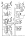
- Fig. 1 shows an example of a constitution of a conventional copying machine, which is a middle-scale OA equipment.
- This copying machine uses total six one-chip CPUs for control of each section of the machine, and each one-chip CPU integrally includes cheap ROM, RAM, I/O control unit, and analog-to-digital (A/D) converter.
- ROM read-only memory
- RAM random access memory
- I/O control unit read-only memory
- A/D analog-to-digital converter
- Objects to be controlled in the copying machine body 100 are distributingly controlled by four one-chip CPUs.
- a master CPU 110 mainly performs an operation-display sequence control 111.
- a slave CPU-A 112 mainly performs a control 113 of a stepper motor and a developer.
- a slave CPU-B 114 mainly performs a control 115 of a DC servo motor in a PLL manner.
- a slave CPU-C l16 mainly performs a control 117 of a potential of a photo sensitive material, erasing, and stabilization of a light amount of a halogen lamp for exposure.
- a slave CPU-D 120 controls an auto document feeder (ADF) 121.
- a slave CPU-E 130 controls a sorter 131. Hitherto, those one-chip CPUs are mutually connected by a control bus consisting of a number of signal lines.
- the ADF 121 and sorter 131 are merely connected to the peripheral devices of the machine, so that total six one-chip CPUs including the objects to be controlled of the copying machine body are used.
- Fig. 2 shows a block arrangement in the case where a system constitution was increased.
- Fig. 3 shows an example of the arrangement of Fig. 2.
- the sorter-I 131 corresponds to the sorter 131 in Fig. 1.
- a sorter-II 141 is the same as the sorter-I and connected in series.
- a paper deck 151 and a charge counter 161 are also connected.
- Fig. 2 shows an example in which the control elements are mutually connected by way of serial communication.
- a constant protocol is determined in communication among the CPUs.
- the address information and data information are time-sharingly transmitted through the bus.
- the overhead due to the program control extremely increases.
- the program process must be carried out to decode the received data, so that it also takes a fairly long time for the decoding.
- the method of Fig. 2 is improper for a response which requires a high speed.
- Another object of the invention is to provide a system for controlling image formation in which a plurality of objects to be controlled are certainly controlled by way of a simple control procedure.
- Still another object of the invention is to provide a system for controlling image formation in which eten when the number of objects to be controlled increases or -decreases, control data lines-among the objects to be controlled can be easily wired and it is also possible to easily cope with a change in system configuration .
- Still another object of the invention is to provide a system for controlling image formation in which a plurality of control units to individually and independently control a plurality of objects to be controlled, transmission control units to transmit control data from the control units to external control execution units, and monitor control units to concentratedly monitor the plurality of control units are integrally formed on a semiconductor substrate.
- Still another object of the invention is to provide a control system comprising: a plurality of control execution units to individually and independently control a plurality of objects to be controlled; a plurality of transmission lines to transmit data to control the control execution units; a plurality of input/output interface units provided for each of those plurality of transmission lines; and a central control unit to control those plurality of I/O interface units.
- Fig. 4 is a schematic cross sectional view of a mechanism section of a desk-type automatic both face copying machine of one embodiment according to the present invention.
- This embodiment is mainly constituted by four blocks of paper feed and conveying system, exposure system, image formation system, and control system. The operation of the embodiment will then be described hereinbelow with reference to Fig. 4.
- the user When copying, the user first opens an original plate cover 1 and sets an original (document) on it. In the case of reducing or enlarging the original image, a variable magnification is set as necessary using a variable magnification key of an operating section (not shown). Further, a copy quantity, auto or manual operation of a concentration, and one-face or both-face copy mode are respectively selected by the relevant keys of the operating section.
- the copy mode is set to the both-face and a copy start key of the operating section is depressed.
- a halogen lamp 3 is lit on and subsequently a photo sensitive drum 20 starts rotating and a charge corona 13 is energized, thereby charging the drum 20.
- the halogen lamp (exposure lamp) 3 and a first mirror 4 are the same structure and scan an original surface 2 synchronously with the rotation of the drum 20.
- An original image is formed on the surface of the drum 20 along an optical axis consisting of the first mirror 4, a second-mirror 5, a third mirror 6, a zoom lens 11, a fourth mirror 7, a fifth mirror 8, and a sixth mirror 9, so that a latent image is formed on the surface of the drum 20.
- the surface potential of the portion on the surface of the drum 20 where no latent image is formed is removed by an eraser lamp 15 in accordance with the paper size. Thereafter, the surface of the drum 20 on which the latent image was formed reaches a developing unit 17 and the toner is deposited on the latent image on the drum surface in accordance with the potential thereof, so that the latent image appears.
- a paper cassette 22 or 24 is selected and a transfer paper is fed by a corresponding paper feed roller 21 or 23 from the selected cassette.
- This transfer paper stands by for feeding by resist rollers 30.
- the resist roller 30 rotates at a predetermined timing synchronized with the rotation of the photo sensitive drum 20 and the position of the transfer paper is aligned with the image on the surface of the drum 20.
- a transfer corona 14 is energized, so that the image on the drum surface is transferred onto the transfer paper.
- the transfer paper is then separated from the drum 20 by a paper separating roller 31 and conveyed to a fixing unit 33 by a paper conveying belt 32.
- the transfer paper is heated and pressed by the fixing unit 33, so that the toner is melted and adhered onto the transfer paper.
- the transfer paper is led to paper delivery rollers 37 by way of a paper guide plate 34 and is once brought onto a both face paper delivery plate 38. This paper then slides down due to the weight of itself and reaches rollers 39. The paper is then delivered by. the rollers 39 and stocked in an intermediate cassette 26. The transfer papers are not stocked on the plate 38 but slide down one by one.
- the papers whose front surfaces have been copied as many as a preset quantity are sequentially stocked in the intermediate cassette 26.
- the image on the surface of the drum 20 after completion of the transfer is removed in a cleaning unit 19 and the drum surface is cleaned.
- the residual toner deposited on the drum surface is removed.
- the light of a charge eraser lamp 18 is irradiated onto the drum surface, thereby removing the residual potential on the drum surface.
- the drum surface 20 is newly charged by the charge corona 13 and a predetermined surface potential is developed on the drum, thereby enabling a new image to be formed.
- An intermediate paper feed roller 25 rotates at a predetermined timing synchronized with the rotation of the photo sensitive drum 20, so that a transfer paper is fed from the intermediate cassette 26.
- This paper is reversed upside down by a guide plate 29 and interposed between the resist rollers 30. The paper stands by until a start signal is inputted at a predetermined timing to align the paper with the point of an image which is formed on the drum surface.
- the resist rollers 30 rotate at a predetermined timing to align the point of the image and the image formed on the drum 20 is transferred.
- the transfer corona 14 is energized at a predetermined timing and the image is transferred on the back surface.
- the paper is separated from the drum 20 by the paper separating roller 31 and conveyed to the fixing unit 33 by the conveying belt 32.
- the toner deposited on the transfer paper is melted and adhered by the fixing unit 33.
- the transfer paper is then interposed between rollers 40.
- the guide plate 34 then serves to lead the paper to a paper delivery plate 36 since the back-side copy has already been finished.
- the transfer paper in which both surfaces were copied is stocked on the paper delivery plate 36. In this manner, the process for both-face copy is completed.
- the paper fed from the cassette 22 or 24 is conveyed as a white paper (namely, the copy is not performed) to the intermediate cassette 26 since only the paper conveying system is energized.
- the operation of the image formation system is not performed at all but only the conveying system operates to feed the paper from the cassette 22 or 24 and convey it to the intermediate cassette 26.
- this embodiment is provided with an automatic exposure function to improve a copy quality.
- the potential of the photo sensitive surface of the drum 20 is controlled to become a constant value and thereby making it possible to always obtain a good concentration irrespective of concentration of the original.
- the surface potential is first monitored. Practically speaking, the lights reflected from a standard reflecting plate 10 are irradiated onto the drum 20 and the surface potential produced at this time is monitored by a surface potential sensor 16, thereby first controlling the corona voltage of the charge corona 13 so that the surface potential becomes a proper value.
- the optical system prescans the original to monitor the original concentration and sets the corona voltage and bias value.
- a value of the development bias may be controlled so that a proper concentration is derived while successively monitoring the original concentration in a realtime manner.
- the concentration can be set to a proper value from the second paper by controlling the corona voltage and a light quantity of lamp.
- an automatic document feeder hereinafter, referred to as an ADF
- a leader or collator a paper deck
- a charge counter etc.
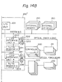
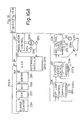
- Fig. 5 shows a block diagram of control functions of the first embodiment.
- reference numeral 200 denotes a main control unit of the copying machine
- 221 to 223 are controllers n 1 to n 3 to control the operation of each constitution of the copying machine under the control of the main control unit 200.
- three controllers are shown as examples in Fig. 5, only an arbitrary number of controllers for extension can be connected to a LAN bus 260 from a LAN interface unit 210 in the main control unit 200.
- Numeral 240 indicates an external memory for extension which can be directly connected to a system bus 204 of the main control unit 200
- 250 represents an external input/output (I/O) device which can be connected to the system bus 204.
- reference numeral 201 denotes a monitor CPU to control the whole system including a CPU 300 of the control system and a schedule for execution of the process;
- 202 is a random access memory (RAM);
- I/O input/output
- 204 the system bus;
- 210 the LAN interface unit serving as an interface among external controllers n 1 to n m ;
- 211 and 212 a Tx address register and a Tx data register for allowing the control CPU 300 to send control data through the LAN interface unit 210 to external controllers.
- An Rx address register 213 and an Rx data register 214 serve to allow the control CPU 300 to receive the data which was sent from the external controller to the LAN interface unit 210 through the LAN bus 260.
- the control CPU 300 executes each task process on the basis of the control of the monitor CPU 201 and is constituted by total eight CPUs 310 to 380 (i.e., CPU-a to CPU-h).
- the number of CPUs of the control C P U 300 can be freely increased or decreased as necessary.
- each control CPU is provided with a dedicated reference register (hereinafter, referred to as a REF register) 354, a timer/ counter 352, a comparator 353, and a control circuit 355.
- the circuits constituting the main control unit 200 are all together constituted on the same one-chip semiconductor substrate.
- each CPU occupies the system bus 204 is sequentially and time-sharingly set as shown in Fig. 6.
- the CPU-a 310 to CPU-h 380 cyclically and time-sharingly operate in a clockwise manner.
- each CPU possesses the system bus 204 for eight ⁇ sec and one rotation equals eighty psec.
- the monitor CPU 201 operates in parallel during this period of time. Therefore, when 80 psec is considered as a unit, the CPU-a to CPU-h operate in parallel.
- the LAN interface unit 210 has a control register and a working register (not shown) and has a function to control the communication of data with the external controllers (221 to 223) or the like through the LAN bus 260 in accordance with a predetermined protocol.
- the small-scale control CPU 300 is assigned for every execution-level of each task process and each CPU independently executes the control process.
- the monitor CPU 201 executes the control of start and stop of the task processes of the respective CPUs of the control CPU 300, designation and change of the execution tasks, and the like. Also, only when a request is generated from the CPUs, the monitor CPU 201 executes the process according to the request.
- a drum clock 206 which is generated due to the rotation of the photo sensitive drum 20 is counted and various kinds of controls are executed synchronously with the drum clock 206.
- the drum clock 206 is sequentially counted by the timer/counter 352 of the CPU-e 350.
- a count value of the timer/counter 352 and a value which is read out from a ROM 255 as necessary by the control of the control circuit 355 and is set into the REF register 354 are compared by the comparator 353. When those values coincide, the next control operation is executed.
- the readout from the RAM 255 into the REF register 354 is performed by way of a DMA.
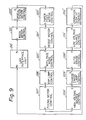
- Fig. 7 is an arrangement diagram of showing respective objects to be controlled which were connected to the main control unit through the LAN bus 260 of the embodiment.
- the objects to be controlled of the copying machine are divided into twelve blocks and the controller of each block is connected to the LAN bus 260.
- the LAN bus 260 is constituted by two signal lines of an output signal line Tx 260a from the LAN interface unit 210 and an input signal line Rx 260b to the LAN interface unit 210.
- the main motor control 221 controls a main mator 221a of the copying machine.
- the main motor 221a drives the conveying system of the drum 20.
- a DC servo motor is used as the main motor.
- the timing clock pulse (drum clock) signal 206 is generated synchronously with the rotation of the drum 20 and is sent to the timer/counter (e.g., 352) of the LAN interface unit 210.
- An optical system motor control 222 controls a scan motor 222a as a servo motor of an original and a pulse motor 222b to set a magnification. The positions and speeds of those motors are controlled by the optical system motor control 222 on the basis of the data from the control CPU 300 in the main control unit 200.
- a variable (reduction, enlargement, zoom) magnification is set by the pulse motor 222b on the basis of-a command. from the control CPU 300.
- the user instructs and inputs the value of the magnification from the operating section.
- the paper feed control 223 controls DC motors 223a and 223b to rotate the paper feed roller 21 or 23 at a predetermined timing.
- the control 223 also detects the presence or absence of the paper in the feed cassette 22 or 24, the paper jam, and the like and transmits the direction data to the control C PU 300.
- a resist control 224 controls a resist motor 224a to drive the resist rollers 30 and controls the image edge registration of the image on the surface of the drum 20 and the transfer paper, and the bending (loop) of the paper, and also detects the double feed (i.e., two papers are simultaneously fed).
- a both-face mode control 225 controls an intermediate paper feed roller motor 225a to drive the paper feed roller 25 and thereby feeding the transfer paper.
- the both-face mode control 225 drives a guide plate control solenoid 225b to control the direction of the guide plate 34 and also detects the presence or -absence (paper jam, presence or absence of the paper) of the transfer paper which is fed in the both-face copy mode.
- An exposure (EXP) lamp control 226 stabilizes a light quantity of the halogen lamp 3 and controls the light adjustment.
- the light quantity of the lamp 3 is detected by a photo sensor 226a.
- the photo sensor 226a is arranged on the side surface of the halogen lamp 3 and continuously monitors the brightness of the lamp 3.
- a fixing heater control 227 controls a heating temperature of a fixing heater 33a of the fixing unit 33. This temperature is detected by a thermistor 227a arranged near the fixing heater 33a and the driving electric power of the heater 33a is controlled on the basis of the detected temperature.
- a high voltage source control 228 measures the detected potential of the surface potential sensor 16 arranged near the drum 20 and controls the voltages of the charge corona 13, transfer corona 14, and a bias voltage source BI 228a so that the surface potential of the drum 20 becomes constant in both the bright and dark portions.
- a charge eraser lamp control 229 controls an irradiation amount of light of the charge eraser lamp 18 to erase the charges on the drum surface. In the case where the image on the drum surface is not transferred onto the transfer paper because of occurrence of paper jam in the transfer unit or the like upon feeding of the paper, or the like, the irradiation amount of light from the lamp 18 is increased, thereby irradiating the high-power light onto the drum surface.
- An auto erase control 230 controls an area where the eraser lamp 15 is lit on in accordance with the size of transfer paper to be copied and with the magnification and erases the charges in the area other than the image transfer area of the surface of the drum 20, thereby preventing the toner from being deposited on the surface in the non-transfer area.
- a low voltage source control 231 regulates the power source voltage of DC 24V and monitors the abnormal value such as an excessive current or the like, and the like.
- An operation-display control 232 serves as a man-machine interface and controls the key inputs from a keyboard 203a of the I/O unit 203 through the control CPU 300 and LAN interface unit 210, the display of a display unit 203b, and the audio output from an audio output unit 232a using an audio synthesizer included in the control 232.
- optical units are provided as peripheral devices which can be connected to the LAN bus 260: namely, a charge counter 234, an OCR/OMR reading apparatus (OCR) 235, an auto document feeder (ADF) 236, and a sorter 237.
- OCR OCR/OMR reading apparatus
- ADF auto document feeder
- a LAN interface is newly provided in the main control unit 200 and used as the LAN interface only for use of the peripheral devices.
- Two sets of Rx and Tx registers which can control two LAN interfaces may be provided in the control CPU 300.
- each control unit will then be described with respect to the main motor control 221 shown in Fig. 7 as an example.
- Each of the other control units is also constituted and controlled in substantially the same manner as the main motor control 221.
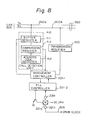
- Fig. 8 is a block diagram mainly showing the transmission control unit of the main motor control 221.
- reference numeral 410 denotes a call detection unit comprising: a buffer register 411 which always receives communication data on the Tx line 260a of the LAN bus 260; an address code register 412 which sets and holds a peculiar address value in the self-control; and a comparison register 413 to compare the address code value in the communication data stored in the buffer address register 411 with the address code value set in the address code register 412. When it is determined in the comparison register 413 that those address code values coincide, it outputs an interruption request to a management controller 221-1 and takes in the data of the transmission frame in which the address code to the self-control was set and which was received in the buffer register 411.
- a PLL control unit 221-2 to drive the main motor is controlled in accordance with the above-mentioned reception data.
- this transmission data is set into a transmission register 420 and the content of the register 420 is transmitted to the Rx line 260b of the L AN bus 260.
- this transmission data there are two kinds of data: one is the data indicative of a request for transmission (for example, status data of the control system) which is transmitted in the case where, e.g., a request for transmission of a constant data is generated from the control CPU 300; and the other is the data indicative of the abnormal state which is transmitted in the case where some accidents occurred.
- a request for reception of the communication data to the self-apparatus is generated to the management controller only when the transmission frame to the self-control is sent by the call detection unit 410 (provided for all controls). Therefore, the management controller does not need to monitor the communication data to the other control during that interval and can execute only its own control process.
- control CPU 300 also controls only the controller which was set and specified in the Tx address register 211, so that the CPU 300 can execute only its own task process without taking account of the interruption request process from the other controller or the like. Therefore, the processing program procedure also becomes simple and has a high reliability.
- the management controller 221-1 outputs a start/stop signal of the main motor 221a to the P LL controller 221-2 and controls the rotation period of time of the main motor 221a.
- the PLL controller 221-2 rotates the motor in response to the start/stop signal and receives a clock pulse signal for control of the speed and position which is generated from a speed controlling encoder 221b in correspondence to the rotation of the motor.
- the PLL controller 221-2 keeps the rotating speed constant on the basis of the clock pulse signal and also outputs the position control data to the management controller 221-1.
- the drum clock pulse 206 which is generated synchronously with the rotation of the drum 20, is generated from an encoder 221c arranged at the other end of the main motor 221a.
- This clock pulse is inputted to the main control unit 200 through another sole signal line different from the LAN bus 260 and inputted to the timer/counter 352 or the like.
- the mutual communication can be realized by a single line instead of two transmission and reception lines.
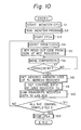
- Fig. 10 is a flowchart for the control operation regarding the EXP lamp control 226. The control procedure for the control through the LAN interface unit 210 and LAN bus 260 will then be described with reference to Fig. 10,
- the monitor CPU 201 in the main control unit 200 first starts a predetermined control in step Sl.
- a monitor program is then executed in step S2. For example, when the copy start key of the keyboard 203a is depressed in that state, the halogen lamp (exposure lamp) 3 is needed to be lit on.
- the monitor CPU 201 instructs and actuates the CPU-e 350 to light on the halogen lamp 3 in step S3.
- the other control CPU 300 actuates the main motor control 221 to rotate the main motor 221a.
- the drum clock 206 is sent in association with the rotation of the motor 221a.
- the CPU-e 350 starts counting the drum clock 206 by way of the timer/ counter 352 in step S4.
- the code data indicative of the light-on timing of the halogen lamp 3 is read out from the ROM 255 and set into the REF register 354.
- the comparator 353 compares the value of the REF register 354 with the count value of the drum clock pulse 206 of the timer/counter 352 and a check is made to see if they coincide or not.
- step S8 follows and the address code of the EXP lamp control 226 is set into the Tx address register 211 in order to instruct the control 226 to light on the halogen lamp 3. Then, the control data (in this case, the light-on control data and light adjustment data of the halogen lamp 3) are set into the Tx data register 212 in step S9.
- the LAN interface unit 210 executes the transmission control to transmit both data from the LAN bus 260 in step S10.
- the control data transmitted to the LAN bus 260 is determined to be the transmission data to the self-control by the call detection unit in the EXP lamp control 226 and is taken in.
- the halogen lamp 3 is lit on in accordance with the control data stored in the Tx data register 212.
- a predetermined brightness is kept in accordance with the light adjustment data.
- the brightness is detected by the photo sensor 226a and converted into an electrical signal proportional to the intensity of the received light by the photo sensor 226a. This analog electrical signal is converted to a digital signal and a value of this digital signal is compared with the light adjustment data sent. A control is made so that they coincide.
- step S9 After the CPU-e 350 set the control data in the Tx data register 212 in step S9, it checks whether the task process which is being executed, namely, all the control for the EXP lamp control 226 have been completed or not in step Sll. Unless it is completed, the processing routine is returned to step S4 and the counting of the drum clock 206 is continued. Further, in step S5, the timing code for the next control is read out from the ROM 255. In this case, for example, the code data indicative of the light-off timing of the halogen lamp 3 is read.
- step S12 follows step Sll and the CPU - e 350 informs the end of task process to the monitor CPU 201 and stops the operation and then waits for actuation from the monitor CPU 201.
- connection among the main control unit 200 and the other control units can be realized by only one or two communication media.
- the peripheral devices (234 to 237) can occupy the LAN bus 260 by requesting the interruption to the LAN interface unit 210 independently of the other controls.
- the interruption requests can be sent through an interruption request signal line 265 shown in Fig. 5.
- Each control unit and peripheral devices can independently control the system to be controlled on a unit basis and can perform the standard control (fail- sale) even if the communication from the main control unit 200 stops for a short time.
- a plurality of control units which independently and respectively control a plurality of objects to be controlled execute time-sharingly the control operations; therefore, it is sufficient that each control unit executes its own control.
- the processing program procedure is simplified and its reliability increases.
- the control operations are time-sharingly performed, so that a collision of the processes does not occur.
- optical equipment for extension can be easily added to the standard apparatus and a constitution can be also easily changed.
- the second embodiment also relates to the control system of the copying machine of Fig. 4 similarly to the first embodiment.
- FIG. 11 the parts and components having the same functions as those shown in Fig. 5 are designated by the same reference numerals.
- reference numeral 200' denotes a main control unit of the copying machine
- 1225 and 1226 indicate optional devices which can be connected to the main control unit 200'.
- the devices 1225 include the sorter-I 131, sorter-II 141, ADF 121, and paper deck 151 shown in Figs. 2 and 3.
- the devices 1226 include a reader, an OCR, an OMR, etc. (not shown). These controls and devices as many as only an arbitrary number can be connected for extension to a LAN bus A 1260 from a LAN interface unit A 1210 or a LAN bus B 1265 from a LAN interface unit B 1215 in the main control unit 200.
- the LAN interface unit A 1210 serves as an interface among the respective controllers in the system.
- Reference numeral 1211 denotes a Tx/Rx register A for allowing the control CPU 300 to send control data to the controllers through the LAN interface unit A 1210.
- Fig. 11 shows the state in that the Tx/Rx register A 1211 is connected to only a control unit e 351 provided in the CPU-e 350, it can be also connected to all of the control CPUs together with the LAN interface unit B 1215 which will be explained hereinafter.
- the LAN interface unit B 1215 serves as an interface among the external devices 1225 and 1226 and transmits data among the control CPU 300 and the external devices through a Tx/Rx register B 1216.
- Each of the Tx/Rx registers A and B (1211, 1216) comprises 10-bit address register and data register for transmission and 10-bit address register and data register for reception.
- the circuits constituting the main control unit 200' are all constituted on a one-chip semiconductor substrate. Silicon may be used as a semiconductor.
- the time when each CPU occupies the system bus 204 is sequentially and time-sharingly set as shown in Fig. 6 in a manner similar to the first embodiment.
- the CPU-a 310 to CPU-h 380 time-sharingly and cyclically operate in a clockwise manner.
- each CPU occupies the system bus 204 for eight psec and it takes eighty ⁇ sec for one rotation. Therefore, when 80 psec is considered as a unit, the CPU-a 310 to CPU-h 380 operate in parallel.
- the monitor CPU 201 operates in parallel with the control CPU 300 during this period of time.
- Each of the LAN interface units A 1210 and B 1215 has a control register and a working register (not shown) and also has a function to execute the communication control of data among the controllers and the external devices or the like through the LAN buses A 1260 and B 1265 in accordance with a predetermined protocol.
- a small-scale control CPU 300 is assigned for every execution level of each task process in addition to the monitor CPU 201 and each CPU independently executes the control process.
- the monitor CPU 201 executes the control of start and stop of the task processes of the respective CPUs of the control CPU 300, designation and change of the execution tasks, etc. Only when requests are generated from respective CPUs, the monitor CPU 201 executes the processes corresponding to the requests.
- Fig. 12 shows four representative units as peripheral devices which can be optionally connected to the LAN bus B 1265: namely, the charge counter 234, OCR/OMR reading apparatus (OCR) 235, auto document feeder (ADF) 236,.and-sorter 237. These devices are connected through the LAN bus B 1265 in accordance with the control of the LAN interface unit B 1215.
- OCR OCR/OMR reading apparatus
- ADF auto document feeder
- the constitution and control operation of the main motor control 221 shown in Fig. 12 according to the second embodiment are substantially the same as those of the main motor control 22l shown in Fig. 8 in the first embodiment.
- a plurality of internal controllers in the main body are connected to the LAN interface unit A 1210 and a plurality of external optional devices to be connected to the main body are connected to the LAN interface unit B 1215.
- the mutual communication can be realized by way of a single line instead of two lines for transmission and reception.
- control operation of the control through the LAN interface unit A 1210 and LAN bus A 1260 for example, the control operation for the EXP lamp control 226 is similarly performed in accordance with the flowchart of Fig. 10 in the first embodiment.
- two LAN interfaces for internal and external uses are provided and they can operate synchronously or asynchronously with each other and the system control can be efficiently carried out.
- system equipemnt can be added or deleted without particularly changing the constitution.
- the second embodiment of the present invention it is possible to provide a reliable apparatus in which a quantity of wirings in the system is little and which is not adversely influenced by the other signal lines. Also, various kinds of optional equipment for extension can be extremely easily added to the standard apparatus and the constitution can be also easily changed.
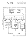
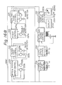
- Fig. 14 shows a block diagram of a control function of the third embodiment of the present invention.
- a reference numeral 200" denotes a main control unit of the copying machine.
- External controllers and devices as many as only an arbitrary number can be connected for extension to an optical fiber A 2260 from an electrical-optical converting unit (hereinafter, referred to as E/O) A 2213 of a LAN interface unit A 2210 or an optical fiber B 2265 from an E/O B 2218 of a LAN interface unit B 2215 in the main control unit 200".
- E/O electrical-optical converting unit
- the LAN interface unit A 2210 serves as an interface among the controllers in the system.
- a reference numeral 2211 denotes a Tx/Rx register A for allowing the control CPU 300 to send control data to the controllers through the LAN interface unit A 2210.
- Fig. 14 shows the state in that the Tx/Rx register 2211 is connected to only the control unit e 351 provided in the CPU-e 350, it can be connected to all control CPUs together with the LAN interface unit B 2215 which will be explained hereinafter.
- the LAN interface unit B 2215 serves as an interface among the external devices 225 and 226 and transmits data among the control CPU 300 and the external devices through a Tx/Rx register B 2216.
- Each of the Tx/Rx registers A and B (2211 and 2216) comprises 10-bit address register and data register for transmission and 10-bit address register and data register for reception.
- Numerals 2212 and 2217 indicate optical-electrical converting units (hereinafter, referred to as O/E) A and B which receive optical data from the optical fibers A 2260 and B 2265 and convert to electrical signals.
- Numerals 2213 and 2218 denote the E/O A and E/O B to convert data transmitted from the LAN interface units A 2210 and B2215 to optical communication data.
- the circuits constituting the main control unit 200" are all together constituted on a one-chip semiconductor substrate. Silicon or gallium may be used as a semiconductor.
- the time when each CPU occupies the system bus 204 is sequentially and time-sharingly set. as shown in Fig. 6 in a manner similar to the first and second embodiments.
- the CPU-a 310 to CPU-h 380 time-sharingly and cyclically operate in a clockwise manner.
- each CPU occupies the system bus 204 for eight ⁇ sec and it takes eightly psec for one rotation. Therefore, when 80 psec is considered as a unit, the CPU-a 310 to CPU-h 380 operate in parallel.
- the monitor CPU 201 operates in parallel with the control CPU 300 during this period of time.
- Each of the LAN interface units A 2210 and B 2215 has a control register and a working register (not shown) and also has a function to control the data communication among the controllers and the external devices or the like through the optical fibers A 2260 and B 2265 in accordance with a predetermined protocol.
- the small-scale control CPU 300 is assigned for every execution level of each task process. Each CPU independently executes the control process.
- the monitor CPU 201 executes the control of start and stop of the task processes of the respective CPUs of the control CPU 300, designation and change of the execution tasks, etc. Only when requests are generated from the respective CPUs, the monitor CPU 201 executes the processes corresponding to the requests.
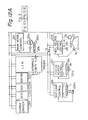
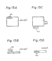
- the main control unit 200" is integrally constituted in a leadless package and its external views are shown in Figs. 15A to 15D.
- Fig. 15A is a top plan view of the integrated leadless package of the main control unit 200" and Fig. 15B is a front view of the same, in which reference numeral 400 denotes a lead package chip and 410 indicates optical fiber connectors. Two pairs of optical connectors are included on the top surface of the leadless package as shown in Figs. 15A and 15B.
- Figs. 15C and 15D show an example whereby the optical fiber connectors 410 are arranged on the side surface instead of the top surface of the leadless package 400.
- Fig. 15C is a top plan view and Fig. 15D is a front view.
- the O/E A 2212, O/E B 2217, E/O A 2213 and E/O B 2218 are one-chipped in the main control unit 200" so that the optical communication can be performed and each of these converters is equipped with a light emitting diode (LED) consisting of the gallium arsenide (GaAs) system, thereby allowing the signals in the chip to be directly converted.
- LED light emitting diode
- GaAs gallium arsenide
- an avalanche photo diode (APD) serving as a photosensing device is likewise one-chipped.
- the main control unit (controller) in this invention has a feature such that the above-mentioned optical integrated circuit and VLSI are integrated and one-chipped in the same package or as a VLSI consisting of gallium system.
- the main control unit 200" is connected to other controllers by way of the daisy chain system. Each controller once performes the O/E conversion and decodes the address and takes in data if it is the transmission data to the self-unit. Then, the controller executes the process corresponding to the data taken. In the case where the data is the data to the other controller, it is immediately E/O converted and sent to the next controller (unit).
- Fig. 16 is an arrangement diagram of the objects to be controlled which were connected to the main control unit through the optical fibers A 2260 and B 2265 of this embodiment.
- the objects to be controlled of the copying machine are divided into twelve blocks and the controller in each block is connected through the optical fiber.
- This optical fiber uses the daisy chanin system in which the optical output from the LAN interface A 2210 or B 2215 sequentially circulates through the respective controllers and is inputted to the LAN controller.
- the main motor control 221 controls the main motor 221a of the copying machine.
- the main motor 221 a drives the conveying system of the photo sensitive drum 20.
- a DC servo motor is used as a main motor.
- the timing clock pluse (drum clock) signal 206 is generated synchronously with the rotation of the drum 20 and sent to the timer/ counter (e.g., 352) in the LAN interface unit A 2210.
- the optical system motor control 222 controls the scan motor 222a of an original serving as a servo motor and the pulse motor 222b to set a magnification. The positions and speeds of those motors are controlled by the motor control 222 on the basis of the data from the control CPU 300 of the main control unit 200.
- variable magnification (reduction, enlargement, zoom) is set by the pulse motor 222b on the basis of a command from the control CPU 300.
- a value of the magnification is instructed and inputted by the user from the operating section.
- the paper feed control 223 controls the DC motor 223a or 223b to rotate the paper feed roller 21 or 23 at a predetermined timing and also detects the presence or absence of the papers in the paper feed cassette 22 or 24, the paper jam, etc. and transmits the detection data to the control CPU 300.
- the resist control 224 controls the resist motor 224a to drive the resist rollers 30, controls the image edge resist of the image on the surface of the drum 20 and transfer paper, controls the bending (loop) of the paper, and detects the double feed (i.e., two papers are simultaneously fed). In the case where the user sets the both-fach copy mode, the papers of which the one-side copy has been completed as described above are sent to the intermediate cassette 26.
- the both-face mode control 225 controls the intermediate paper feed roller motor 225a to drive the paper feed roller 25 to feed the papers from the intermediate cassette 26 upon completion of the one-side copy of the papers as many as a specified quantity, thereby feeding the transfer papers.
- the both-face mode control 225 drives the guide plate control solenoid 225b to control the direction of the guide plate 34 and also detects the presence or absence (paper jam, presence or absence of the papers) of the papers in the both-face copy mode.
- the EXP lamp control 226 stabilizes a light quantity of the halogen lamp 3 and controls the light adjustment. A light quantity of the halogen lamp 3 is detected by the photosensor 226a.
- the photo sensor 226a is arranged on the side surface of the lamp 3 and continuously monitors the brightness of the lamp 3.
- the fixing heater control 227 controls a heating temperature of the fixing heater 33a of the fixing unit 33. This temperature is detected by the thermistor 227a arranged near the fixing heater 33a. A driving electric power of the heater 33a is controlled in accordance with the temperature detected.
- the high voltage source control 228 measures the detection potential of the surface potential sensor 16 arranged near the surface of the drum 20 and controls the voltages of the charge corona 13, transfer corona 14, and bias voltage source BI 228a so that the surface potential of the drum 20 becomes constant in both bright and dark portions.
- the charge eraser lamp control 229 controls an irradiation amount of the charge eraser lamp 18 to erase the charges of the drum surface. In the case where the image on the drum surface is not transferred onto the transfer paper due to occurrence of the paper jam upon feeding of the paper in the transfer unit or the like, or in other similar case, the irradiation amount from the charge eraser lamp 18 is increased, thereby irradiating a high power light onto the surface of the photosensitive drum 20.
- the auto erase control 230 controls the area where the erase lamp 15 is lit on in accordance with a size of the transfer paper to be copied and with a variable magnification and erases the charges in the area other than the image transfer area of the drum surface, thereby preventing the toner from being deposited onto the surface in the non-transfer area.
- the low voltage source control 231 regulates the power source voltage of DC 24V and monitors an abnormal value such as an excessive current, and the like.
- the operation-display control 232 serves as a man-machine interface and controls the key inputs from the keyboard 203a of the I/O unit 203 through the control CPU 300 and LAN interface unit A 2210, the display of the display unit 203b, and an audio output from the audio output unit 232a using the audio synthesizer included in the control 232.
- optical fiber B 2265 from the LAN interface unit B 2215: namely, the charge counter 234, OCR/OMR reading apparatus (OCR) 235, auto document feeder (ADF) 236, and sorter 237. These units are connected to the optical fiber B 2265 in accordance with the control of the LAN interface B 2215.
- OCR OCR/OMR reading apparatus
- ADF auto document feeder
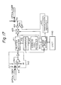
- Fig. 17 shows a block diagram of the transmission control unit from the optical communication medium in the control unit shown in Fig. 16.
- a reference numeral 410 denotes a photosignal receiving unit.
- An avalanche photodiode (APD) 414 in the unit 410 always receives optical communication data transmitted through the optical fiber and photo-electric converts it to an electrical signal. This signal is sequentially stored into the buffer register 411.
- APD avalanche photodiode
- An address code value sot in the address code register 412 to set and hold an address value which is peculiar to the self-control and an address code value in the communication data stored in the buffer register 411 are compared by the comparison register 413. when those values do not coincide, an LED 426 is turned on to emit the light by way of an analog switch 423 (which is normally open) and a buffer 424, thereby transmitting data from the buffer register 411 to the next controller.
- an interruption request is outputted to a management controller 430, thereby setting the data take-in mode of the data of the transmission frame in which the address code to the self-control was set and which was received in the buffer register 411.
- the analog switch 423 is closed and the reception data is taken out from the buffer register 411.
- a unit 440 is controlled in accordance with this reception data.
- this transmission data is set into the transmission register 420.
- the content of the transmission register 420 is transmitted to the control CPU 300 through a buffer 425 by turning on the LED 426 to emit the light.
- the transmission data there are two kinds of data: one is the data indicative of a request for transmission (for example, status data of the control system) which is transmitted in the case where, e.g., a request for transmission of a constant data is generated from the control CPU 300; and the other is the data indicative of the abnormal state which is transmitted in the case where some accidents occurred.
- the management controller does not need to monitor the communication data to other controls during that period of time but can execute only its own control process.
- the E/O and O/E converting units in the transmission control unit and the management controller are constituted as a one-chip monolithic LSI and are loaded in the unit of each object to be controlled.
- control CPU 300 also controls only the controller which was set and specified in the Tx/Rx register A 2211 or B 2216. Therefore, the control CPU 300 can execute only its own task process without taking account of interruption request processes from other controllers or the like, so that the processing program procedure is also simplified and its reliability is improved.
- each CPU has a common register and performs the readout operation from and writing operation into a memory and also the transmission and reception of data among the CPUs. As shown in Fig. 6, however, each CPU time-sharingly and cyclically operates, so that a collision of the processes of the CPUs does not occur and the program can be easily constituted. Therefore, for example, when the CPU-e 350 intends to deliver the papers to a stacker of the sorter at a certain timing, by storing the corresponding data into the common register, the CPU-h 380 reads out a command from the common register 3psec after the operation of the CPU-e 350 and can give the command to the LAN interface unit B 2215.
- this instruction data is received by the LAN interface unit B 2215 and stored into the register to load the copy mode under management of the CPU-h 380.
- the CPU-e 350 reads this data and can execute the operation in the copy mode.
- the management controller controls the main motor in a PLL control manner and outputs a start/stop signal of the main motor 221a, thereby controlling the rotating time of the motor 221a.
- the management controller also rotates the motor under the PLL control in response to the start/stop signal and receives a clock pulse signal to control the speed and position which is generated from the speed control encoder 221b in correspondence to the rotation of the motor, thereby keeping the rotating speed of the motor constant.
- the drum clock pulse 206 which is generated synchronously with the rotation of the photosensitive drum 20, is generated from the encoder 221c arranged at the other end of the main motor 221a and inputted to the main control unit 200" through another sole signal line different from the optical fiber and inputted to the timer/counter 352 or the like.
- control operation of the control through the LAN interface unit A 2210 and optical fiber for example, the control operation for the EXP lamp control 226 is executed in accordance with a flowchart of Fig. 10 in a manner similar to the first and second embodiments.
- the main control unit 200 can be connected with the other controls by way of only a single optical fiber (optical communication medium).
- the peripheral devices (234 to 237) are also controlled by the main control unit 200" through the optical fiber from the LAN interface unit B 2215 in a similar manner.
- the processing speed can be also improved by separately providing two optical fibers from the main control unit 200" for transmission and reception.
- the cost slightly increases in this case, a transmitting efficiency is improved and transmission control is also simplified.
- Fig. 18 shows an example whereby two optical fibers are used.
- reference numeral 800 denotes a photobranch connector
- 810 is a transmitting optical fiber of the main control unit 200
- 820 is a receiving optical fiber of the unit 200".
- data is transmitted among the main control unit 200" and controllers units to be controlled) using two optical fibers.
- Fig. 19 shows a detailed arrangement of each photobranch connector of the optical fibers used in Fig. 18.
- numerals 810 and 820 are similar to the optical fibers 810 and 820 shown in Fig. 18 and 830 denotes a half mirror included in the photobranch connector. This half mirror may be replaced by a prism.
- Each control unit and peripheral device can independently control objects to be controlled on a unit basis and even if the communication from the main control unit 200" stops for a short time, they can perform the standard control (fail-safe).
- two LAN interfaces are provided for both internal and external uses and they can operate synchronously and asynchronously with each other and can efficiently control the system.
- other system equipment can be easily added or deleted without particularly changing the arrangement.
- one of the LAN interfaces may be simply used as an extension port for I/O. In this case, there is no need to connect those LAN interfaces by the optical fiber but this extension port may be used as an ordinary interface.
- the harness can be simplified and disturbance due to the noise can be improved.
- the effective control system can be constituted by the controller based on the new concept in which a photointegrated circuit was integrally formed.
- the present invention can be applied to other image forming apparatuses such as a printer, display device, or the like, or a general control system having a plurality of objects to be controlled.
- each control unit which independently and respectively control a plurality of objects to be controlled execute time-sharingly the control operations. Therefore, each control unit can perform its own control, so that the processing program procedure is simplified and its reliability for control is also improved. A collision of processes does not occur.
- the transmission control unit is integrally constituted with those plurality of control units, it is possible to obtain a reliable system in which a quantity of wirings in the control system is little. Also, various kinds of optional equipment for extension can be extremely easily added to the standard apparatus and a constitution can be also easily changed.
Landscapes
- Physics & Mathematics (AREA)
- General Physics & Mathematics (AREA)
- Engineering & Computer Science (AREA)
- Automation & Control Theory (AREA)
- Control Or Security For Electrophotography (AREA)
Applications Claiming Priority (6)
| Application Number | Priority Date | Filing Date | Title |
|---|---|---|---|
| JP23403484A JPS61114358A (ja) | 1984-11-08 | 1984-11-08 | 制御装置 |
| JP234034/84 | 1984-11-08 | ||
| JP59234035A JPS61114305A (ja) | 1984-11-08 | 1984-11-08 | 制御装置 |
| JP59234036A JPS61114306A (ja) | 1984-11-08 | 1984-11-08 | 制御システム |
| JP234035/84 | 1984-11-08 | ||
| JP234036/84 | 1984-11-08 |
Publications (3)
| Publication Number | Publication Date |
|---|---|
| EP0180988A2 true EP0180988A2 (de) | 1986-05-14 |
| EP0180988A3 EP0180988A3 (en) | 1988-10-05 |
| EP0180988B1 EP0180988B1 (de) | 1992-09-30 |
Family
ID=27332070
Family Applications (1)
| Application Number | Title | Priority Date | Filing Date |
|---|---|---|---|
| EP85114183A Expired EP0180988B1 (de) | 1984-11-08 | 1985-11-07 | Bildgestaltungssteuerungssystem |
Country Status (4)
| Country | Link |
|---|---|
| US (1) | US4980814A (de) |
| EP (1) | EP0180988B1 (de) |
| CA (1) | CA1253912A (de) |
| DE (1) | DE3586711T2 (de) |
Cited By (4)
| Publication number | Priority date | Publication date | Assignee | Title |
|---|---|---|---|---|
| EP0196677A3 (de) * | 1985-04-05 | 1988-11-23 | Tsudakoma Corporation | Zentralisierter Regelvorgang für Webmaschinen |
| GB2244025A (en) * | 1990-03-19 | 1991-11-20 | Ricoh Kk | Control system for image forming equipment |
| EP0377331A3 (de) * | 1988-12-30 | 1993-06-09 | Pitney Bowes Inc. | Meldungsaustausch für eine mehrfache Bearbeitungsstation |
| EP0376738A3 (de) * | 1988-12-30 | 1993-06-09 | Pitney Bowes Inc. | Kommunikation in Dualbetriebsart |
Families Citing this family (10)
| Publication number | Priority date | Publication date | Assignee | Title |
|---|---|---|---|---|
| JP2675814B2 (ja) * | 1988-05-16 | 1997-11-12 | キヤノン株式会社 | 通信装置 |
| US5087940A (en) * | 1990-08-23 | 1992-02-11 | Eastman Kodak Company | Control system for document reproduction machines |
| JP2635438B2 (ja) * | 1990-11-01 | 1997-07-30 | シャープ株式会社 | ズームコピー機能を備えた複写機 |
| JPH0783412B2 (ja) * | 1991-02-12 | 1995-09-06 | 富士ゼロックス株式会社 | 記録装置管理システム |
| US5223897A (en) * | 1991-09-05 | 1993-06-29 | Xerox Corporation | Tri-level imaging apparatus using different electrostatic targets for cycle up and runtime |
| US5530823A (en) * | 1992-05-12 | 1996-06-25 | Unisys Corporation | Hit enhancement circuit for page-table-look-aside-buffer |
| US5520470A (en) * | 1993-10-21 | 1996-05-28 | Telxon Corporation | Portable printer for handheld computer |
| JP2003237144A (ja) * | 2001-12-10 | 2003-08-27 | Canon Inc | 画像処理装置及び画像処理方法及び制御プログラム及び記録媒体 |
| US6792223B2 (en) * | 2002-01-30 | 2004-09-14 | Ricoh Company, Ltd. | Image forming apparatus for reducing a system return time |
| CN108227426B (zh) * | 2018-01-26 | 2019-10-01 | 珠海奔图电子有限公司 | 安全可信的图像形成装置及其控制方法,成像系统及方法 |
Family Cites Families (22)
| Publication number | Priority date | Publication date | Assignee | Title |
|---|---|---|---|---|
| US3579200A (en) * | 1969-07-30 | 1971-05-18 | Ibm | Data processing system |
| US3970993A (en) * | 1974-01-02 | 1976-07-20 | Hughes Aircraft Company | Cooperative-word linear array parallel processor |
| US3980992A (en) * | 1974-11-26 | 1976-09-14 | Burroughs Corporation | Multi-microprocessing unit on a single semiconductor chip |
| US4111543A (en) * | 1976-04-15 | 1978-09-05 | Xerox Corporation | Apparatus and method for noise immunity in distributing control signals in electrostatographic processing machines |
| US4111544A (en) * | 1976-04-15 | 1978-09-05 | Xerox Corporation | Apparatus and method for noise immunity for control signals in electrostatographic processing machines |
| JPS52134732A (en) * | 1976-05-06 | 1977-11-11 | Sharp Corp | Electrophotographic copier |
| US4144550A (en) * | 1977-08-30 | 1979-03-13 | Xerox Corporation | Reproduction machine using fiber optics communication system |
| US4283773A (en) * | 1977-08-30 | 1981-08-11 | Xerox Corporation | Programmable master controller communicating with plural controllers |
| US4253148A (en) * | 1979-05-08 | 1981-02-24 | Forney Engineering Company | Distributed single board computer industrial control system |
| US4304001A (en) * | 1980-01-24 | 1981-12-01 | Forney Engineering Company | Industrial control system with interconnected remotely located computer control units |
| US4500951A (en) * | 1981-01-07 | 1985-02-19 | Hitachi, Ltd. | Plant control system |
| US4443861A (en) * | 1981-04-13 | 1984-04-17 | Forney Engineering Company | Combined mode supervisory program-panel controller method and apparatus for a process control system |
| DE3130862A1 (de) * | 1981-08-04 | 1983-03-31 | Kleindienst GmbH, 8900 Augsburg | Waeschereieinrichtung |
| US4507726A (en) * | 1982-01-26 | 1985-03-26 | Hughes Aircraft Company | Array processor architecture utilizing modular elemental processors |
| DE3230054A1 (de) * | 1982-08-12 | 1984-02-16 | Siemens Ag | Demultiplexer |
| US4532584A (en) * | 1982-09-21 | 1985-07-30 | Xerox Corporation | Race control suspension |
| US4523299A (en) * | 1982-09-21 | 1985-06-11 | Xerox Corporation | Message transmitting system for reproduction machines and copiers |
| US4589090A (en) * | 1982-09-21 | 1986-05-13 | Xerox Corporation | Remote processor crash recovery |
| JPH0666062B2 (ja) * | 1982-10-06 | 1994-08-24 | キヤノン株式会社 | シーケンス制御装置 |
| JPH0666063B2 (ja) * | 1982-10-06 | 1994-08-24 | キヤノン株式会社 | シーケンス制御装置 |
| US4814973A (en) * | 1983-05-31 | 1989-03-21 | Hillis W Daniel | Parallel processor |
| US4689736A (en) * | 1984-05-29 | 1987-08-25 | General Signal Corporation | Distributed process control system |
-
1985
- 1985-11-06 CA CA000494745A patent/CA1253912A/en not_active Expired
- 1985-11-07 DE DE8585114183T patent/DE3586711T2/de not_active Expired - Lifetime
- 1985-11-07 EP EP85114183A patent/EP0180988B1/de not_active Expired
-
1988
- 1988-09-12 US US07/244,638 patent/US4980814A/en not_active Expired - Lifetime
Cited By (6)
| Publication number | Priority date | Publication date | Assignee | Title |
|---|---|---|---|---|
| EP0196677A3 (de) * | 1985-04-05 | 1988-11-23 | Tsudakoma Corporation | Zentralisierter Regelvorgang für Webmaschinen |
| EP0377331A3 (de) * | 1988-12-30 | 1993-06-09 | Pitney Bowes Inc. | Meldungsaustausch für eine mehrfache Bearbeitungsstation |
| EP0376738A3 (de) * | 1988-12-30 | 1993-06-09 | Pitney Bowes Inc. | Kommunikation in Dualbetriebsart |
| GB2244025A (en) * | 1990-03-19 | 1991-11-20 | Ricoh Kk | Control system for image forming equipment |
| GB2244025B (en) * | 1990-03-19 | 1994-03-30 | Ricoh Kk | Control system for image forming equipment |
| US5420665A (en) * | 1990-03-19 | 1995-05-30 | Ricoh Company, Ltd. | Multi-tasking control system for image forming equipment |
Also Published As
| Publication number | Publication date |
|---|---|
| EP0180988B1 (de) | 1992-09-30 |
| CA1253912A (en) | 1989-05-09 |
| EP0180988A3 (en) | 1988-10-05 |
| DE3586711D1 (de) | 1992-11-05 |
| DE3586711T2 (de) | 1993-02-25 |
| US4980814A (en) | 1990-12-25 |
Similar Documents
| Publication | Publication Date | Title |
|---|---|---|
| US5839019A (en) | Image forming apparatus for copying different groups of document | |
| US4980814A (en) | System for controlling image formation | |
| US4206995A (en) | Reproduction machine with on board document handler diagnostics | |
| EP0036304A2 (de) | Kopiergerät zum unterschiedlichen, automatischen Kopieren verschiedener Dokumente | |
| JPH0636237B2 (ja) | 複写機及びコピ−装置用メツセ−ジ伝送システム | |
| EP0240878A1 (de) | Vorrichtung zur Auswahl einer Kassette | |
| US5289236A (en) | Image forming apparatus | |
| US4967240A (en) | Recording apparatus | |
| JPS5975304A (ja) | 多重プロセツサ型制御装置及び入力フイルタ | |
| US4800482A (en) | Sequence controller using pulse counts to activate/deactivate controlled elements | |
| US4967377A (en) | Control system using computers and having an initialization function | |
| GB2128367A (en) | Photocopying machine | |
| US5163137A (en) | Copying system with a dual trunk serial communication system using an acknowledge line | |
| US4576472A (en) | Control apparatus for copying machine | |
| JPH10126536A (ja) | 画像形成装置及びその制御方法 | |
| JP2656509B2 (ja) | 画像形成装置 | |
| US4585333A (en) | Separated communication between electrophotographic copying machine and its subsystem | |
| US5774764A (en) | Image recording apparatus and option control apparatus | |
| JPS63253957A (ja) | データロギングシステム用画像形成装置 | |
| JP2836817B2 (ja) | 画像形成装置 | |
| JPS61114358A (ja) | 制御装置 | |
| JPS61229103A (ja) | 複写機等の制御装置 | |
| US5206695A (en) | Image forming apparatus having sorting function | |
| US5206953A (en) | Data communication system | |
| JPS63268063A (ja) | シリアル通信方式 |
Legal Events
| Date | Code | Title | Description |
|---|---|---|---|
| PUAI | Public reference made under article 153(3) epc to a published international application that has entered the european phase |
Free format text: ORIGINAL CODE: 0009012 |
|
| AK | Designated contracting states |
Kind code of ref document: A2 Designated state(s): DE FR GB |
|
| PUAL | Search report despatched |
Free format text: ORIGINAL CODE: 0009013 |
|
| AK | Designated contracting states |
Kind code of ref document: A3 Designated state(s): DE FR GB |
|
| 17P | Request for examination filed |
Effective date: 19890217 |
|
| 17Q | First examination report despatched |
Effective date: 19900918 |
|
| GRAA | (expected) grant |
Free format text: ORIGINAL CODE: 0009210 |
|
| AK | Designated contracting states |
Kind code of ref document: B1 Designated state(s): DE FR GB |
|
| REF | Corresponds to: |
Ref document number: 3586711 Country of ref document: DE Date of ref document: 19921105 |
|
| ET | Fr: translation filed | ||
| PLBE | No opposition filed within time limit |
Free format text: ORIGINAL CODE: 0009261 |
|
| STAA | Information on the status of an ep patent application or granted ep patent |
Free format text: STATUS: NO OPPOSITION FILED WITHIN TIME LIMIT |
|
| 26N | No opposition filed | ||
| REG | Reference to a national code |
Ref country code: GB Ref legal event code: IF02 |
|
| PGFP | Annual fee paid to national office [announced via postgrant information from national office to epo] |
Ref country code: GB Payment date: 20041104 Year of fee payment: 20 Ref country code: DE Payment date: 20041104 Year of fee payment: 20 |
|
| PGFP | Annual fee paid to national office [announced via postgrant information from national office to epo] |
Ref country code: FR Payment date: 20041109 Year of fee payment: 20 |
|
| PG25 | Lapsed in a contracting state [announced via postgrant information from national office to epo] |
Ref country code: GB Free format text: LAPSE BECAUSE OF EXPIRATION OF PROTECTION Effective date: 20051106 |
|
| REG | Reference to a national code |
Ref country code: GB Ref legal event code: PE20 |