EP0181597A1 - Verfahren zur Herstellung eines Dauermagneten - Google Patents
Verfahren zur Herstellung eines Dauermagneten Download PDFInfo
- Publication number
- EP0181597A1 EP0181597A1 EP85114066A EP85114066A EP0181597A1 EP 0181597 A1 EP0181597 A1 EP 0181597A1 EP 85114066 A EP85114066 A EP 85114066A EP 85114066 A EP85114066 A EP 85114066A EP 0181597 A1 EP0181597 A1 EP 0181597A1
- Authority
- EP
- European Patent Office
- Prior art keywords
- molded body
- orientation
- magnetic field
- molded
- permanent magnet
- Prior art date
- Legal status (The legal status is an assumption and is not a legal conclusion. Google has not performed a legal analysis and makes no representation as to the accuracy of the status listed.)
- Granted
Links
- 238000000034 method Methods 0.000 title claims abstract description 17
- 230000005291 magnetic effect Effects 0.000 claims abstract description 37
- 239000000843 powder Substances 0.000 claims abstract description 12
- 230000005294 ferromagnetic effect Effects 0.000 claims abstract description 11
- 238000001746 injection moulding Methods 0.000 claims abstract description 8
- 239000000463 material Substances 0.000 claims abstract description 7
- 238000000748 compression moulding Methods 0.000 claims abstract description 5
- 239000004033 plastic Substances 0.000 claims description 19
- 239000002994 raw material Substances 0.000 claims description 7
- 239000011159 matrix material Substances 0.000 claims description 6
- 150000001875 compounds Chemical class 0.000 claims description 2
- 230000004907 flux Effects 0.000 description 6
- 238000000465 moulding Methods 0.000 description 6
- 238000010586 diagram Methods 0.000 description 5
- 229910052751 metal Inorganic materials 0.000 description 5
- 239000002184 metal Substances 0.000 description 5
- 238000004519 manufacturing process Methods 0.000 description 3
- 239000000126 substance Substances 0.000 description 3
- XEEYBQQBJWHFJM-UHFFFAOYSA-N Iron Chemical compound [Fe] XEEYBQQBJWHFJM-UHFFFAOYSA-N 0.000 description 2
- 238000005336 cracking Methods 0.000 description 2
- 229910052712 strontium Inorganic materials 0.000 description 2
- CIOAGBVUUVVLOB-UHFFFAOYSA-N strontium atom Chemical compound [Sr] CIOAGBVUUVVLOB-UHFFFAOYSA-N 0.000 description 2
- 229920001169 thermoplastic Polymers 0.000 description 2
- 239000004416 thermosoftening plastic Substances 0.000 description 2
- 229910000859 α-Fe Inorganic materials 0.000 description 2
- 239000004677 Nylon Substances 0.000 description 1
- 229910052788 barium Inorganic materials 0.000 description 1
- DSAJWYNOEDNPEQ-UHFFFAOYSA-N barium atom Chemical compound [Ba] DSAJWYNOEDNPEQ-UHFFFAOYSA-N 0.000 description 1
- 239000004020 conductor Substances 0.000 description 1
- 238000009826 distribution Methods 0.000 description 1
- 238000011156 evaluation Methods 0.000 description 1
- 238000002347 injection Methods 0.000 description 1
- 239000007924 injection Substances 0.000 description 1
- 229910052742 iron Inorganic materials 0.000 description 1
- 238000005259 measurement Methods 0.000 description 1
- 230000005405 multipole Effects 0.000 description 1
- 229920001778 nylon Polymers 0.000 description 1
- 229910052761 rare earth metal Inorganic materials 0.000 description 1
- 230000005417 remagnetization Effects 0.000 description 1
- 229920001187 thermosetting polymer Polymers 0.000 description 1
Images

Classifications
-
- H—ELECTRICITY
- H01—ELECTRIC ELEMENTS
- H01F—MAGNETS; INDUCTANCES; TRANSFORMERS; SELECTION OF MATERIALS FOR THEIR MAGNETIC PROPERTIES
- H01F13/00—Apparatus or processes for magnetising or demagnetising
- H01F13/003—Methods and devices for magnetising permanent magnets
-
- Y—GENERAL TAGGING OF NEW TECHNOLOGICAL DEVELOPMENTS; GENERAL TAGGING OF CROSS-SECTIONAL TECHNOLOGIES SPANNING OVER SEVERAL SECTIONS OF THE IPC; TECHNICAL SUBJECTS COVERED BY FORMER USPC CROSS-REFERENCE ART COLLECTIONS [XRACs] AND DIGESTS
- Y10—TECHNICAL SUBJECTS COVERED BY FORMER USPC
- Y10S—TECHNICAL SUBJECTS COVERED BY FORMER USPC CROSS-REFERENCE ART COLLECTIONS [XRACs] AND DIGESTS
- Y10S264/00—Plastic and nonmetallic article shaping or treating: processes
- Y10S264/58—Processes of forming magnets
-
- Y—GENERAL TAGGING OF NEW TECHNOLOGICAL DEVELOPMENTS; GENERAL TAGGING OF CROSS-SECTIONAL TECHNOLOGIES SPANNING OVER SEVERAL SECTIONS OF THE IPC; TECHNICAL SUBJECTS COVERED BY FORMER USPC CROSS-REFERENCE ART COLLECTIONS [XRACs] AND DIGESTS
- Y10—TECHNICAL SUBJECTS COVERED BY FORMER USPC
- Y10S—TECHNICAL SUBJECTS COVERED BY FORMER USPC CROSS-REFERENCE ART COLLECTIONS [XRACs] AND DIGESTS
- Y10S425/00—Plastic article or earthenware shaping or treating: apparatus
- Y10S425/033—Magnet
Definitions
- the present invention relates to a method of producing a permanent magnet, and more particularly to a method of producing a plastic magnet by molding a plastic material containing ferromagnetic powder through injection molding, compression molding, or the like, in an orientating magnetic field.
- isotropic permanent magnets produced through sinter-molding have been used as rotors of miniature electric motors.
- Such permanent magnets produced through sinter-molding have disadvantages that the moment of inertia is large due to the heavy weight thereof, that faulty products may occur due to cracking and/or chipping caused in the magnets during transportation, in the step of assembling a motor, in the step of press-inserting a rotary shaft into a rotor, etc., and that foreign matter due to chipping caused by the magnets cause motor faults.
- plastic magnets which are permanent magnets obtained in such a manner that a material consisting of plastic matrix and ferromagnetic powder is molded through injection molding, compression molding, or the like, in an orientating magnetic field to thereby produce an orientated and magnetized molded body of a permanent magnet.
- the rotor In a stepping motor which is typical one of miniature motors, the rotor is multi-polarized in the direction parallel to the rotary shaft thereof to form about twenty four magnetic poles on the outer circumference thereof.
- the plastic magnets on the other hand, have surface magnetic flux density such that they can not reach that of isotropic sintered magnets, and therefore, they are used only in extremely limited range of applications, or otherwise, they are subject to polar anisotropic orientation molding to elevate the surface magnetic flux density.
- the present inventors have conducted extensive research in order to obtain plastic permanent magnets having a large magnetic force which could not be obtained in the conventional similar plastic permanent magnets produced in such a manner that a columnar or cylidrical body molded with a material consisting of plastic matrix and ferromagnetic powder is multi-polarized on outer or inner surface of the body to form a plurality of stripes of N and S poles arranged alternately and extending parallelly to the axis of rotation.
- the molded body is once orientated by applying lines of magnetic force only in one directiqn perpendicular to the axis of rotation of the molded body, the molded body can be polarized and magnetized on its outer or inner surface to form a plurality of stripes of N and S poles arranged alternately and extending and extending parallelly to the axis of rotation of the molded body, regardless of its length-to-diameter ratio, and that the thus magnetized molded body has a higher matrix flux density than that of isotropic sintered magnets. Based on this finding, the present invention has been completed.
- a method of producing a permanent magnet in which a material containing forromagnetic powder is molded into a columnar or cylindrical molded body through injection molding, compression molding, or the like, in a magnetic field capable of orientating and magnetizing the ferromagnetic powder, which method comprises the steps of applying a magnetic field to the molded body in the unidirection perpendicular to an axis of rotation of the molded body to orientate and magnetize the molded body so as to have two magnetic poles of N and S, demagnetizing the magnetized molded body, and divisionally remagnetizing the demagnetized molded body on its outer or inner surface so as to form at least two stripes of N and S poles arranged alternately and extending parallelly to the axis of rotation of the molded body.
- the raw material is a plastic compound consisting of ferromagnetic powder of at least 70% by weight and plastic matrix.
- thermosetting one or thermoplastic one Any plastic material, either thermosetting one or thermoplastic one, may be used in the method according to the present invention.
- the ferromagnetic powder so far as it is ferrite of strontium, barium, or the like, a rare earth element, or the like, which can be used to form a permanent magnet.
- a raw material 1 for a plastic magnet, containing plastic substances as a matrix is injected into a desired shape cavity 4 of a metal mold 3 by a cylinder 2 of an injection molding machine.
- the metal mold 3 is vertically sandwiched by a yoke 5 wound with an electromagnetic coil (not shown) for generating a necessary magnetic field.
- lines of magnetic force are unidirectionally generated by the yoke 5 so as to magnetize and unidirectionally orientate a ferromagnetic substance in the raw material 1.
- the resultant molded body is cooled and then taken out of the cavity 4.
- the molded body provided with a rotary shaft 6 made of SUS is orientation- magnetized so as to have two poles as shown in Fig. 2, and the magnetic flux density at the outer periphery of the molded body has a distribution along a sine curve as shown in Fig. 3.
- the molded body is demagnetized and placed in an iron yoke 8 having magnetizing conductors 7 as shown in Fig: 4 (b), where the molded body 4 is divisionally remagnetized in such a manner that a plurality of stripes of N and S magnetic poles arranged alternately and extending parallelly to the axis of rotation of the molded body are formed in the outer periphery of the molded body 4 as shown in Fig. 4 (a).
- the permanent magnet obtained by the method as described above is very excellent because it is superior in property of magnetic force and free from longitudinal deviation in magnetic characteristics, as compared with those obtained in accordance with the orientation techniques such as radial anisotropic orientation, polar anisotropic orientation, etc.
- the orientation performed through the orientating method according to the present invention may be referred to as "perpendioular magnetic field orientation" because a magnetic field is applied to a molded body in the direction perpendicular to the axis of rotation of the molded body.
- a magnetic field is applied to a columnar or cylindrical molded body in the unidirection perpendicular to the axis of rotation of the molded body, so that the ferromagnetic substance contained in the molded body can be easily orientated and the inner or outer surface of the molded body can be magnetized to form multi-poles, and that the resultant molded body is improved in frequency characteristics because of its higher property of magnetic force than those of isotropic sintered magnets as well as because of its light weight.
- the orientating method according to the present invention it is possible to obtain a property of magnetic force which is uniform in the direction of the axis of rotation of the molded body unlike the case of radial orientation, there is no restriction for the structure of the metal mold unlike the case of polar orientation, it is possible to produce numbers of molded bodies at the same time, and it is possible to realize very high productivity.
- thermoplastic magnets made of a raw material consisting of 12 weight % nylon and 88 weight % strontium ferrite.
- molded'bodies were obtained by generating magnetic fields of isotropy orientation, polar anistropy orientation, radial anisotropy orientation, and unidirectional anisotropy orientation, respectively, by using an injection molding machine having coils for generation of an orientation magnetic field.
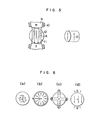
- Each of these molded bodies was a column of 18 mm in diameter and 25 mm in length. The relationship between the direction of orientation the magnetic field, with respect to those molded bodies are shown in Fig. 6.
- the molded articles were then demagnetized and subsequently divisionally magnetized in such a manner that 2 or 24 stripes of N and S poles arranged alternately and extending parallelly to the axis . of rotation of each molded body were formed in the outer circumference of each molded body.
- the resultant molded bodies were evaluated and the results of evaluation are shown in Table 1.
- the multi-polar permanent magnet obtained according to the present invention is superior to the isotropic sintered magnet, in the property of its magnetic force when compared with the sintered magnet, and further found that the plastic magnet of unidirectional anisotropic orientation according to the'present invention can provide a higher performance than other plastic magnets of radial anisotropy orientation and polar anisotropy orientation.
- plastic magnets are free from cracking, chipping, etc., light in weight, and very high in productivity. Therefore, the plastic magnets produced according to the multipolarization technique of the present invention can be effectively substituted for isotropic sintered magnets conventionally used in the field of small motors.
Landscapes
- Engineering & Computer Science (AREA)
- Power Engineering (AREA)
- Manufacturing Cores, Coils, And Magnets (AREA)
Applications Claiming Priority (2)
| Application Number | Priority Date | Filing Date | Title |
|---|---|---|---|
| JP233303/84 | 1984-11-07 | ||
| JP59233303A JPS61112310A (ja) | 1984-11-07 | 1984-11-07 | 永久磁石の製造方法 |
Publications (2)
| Publication Number | Publication Date |
|---|---|
| EP0181597A1 true EP0181597A1 (de) | 1986-05-21 |
| EP0181597B1 EP0181597B1 (de) | 1989-09-27 |
Family
ID=16952999
Family Applications (1)
| Application Number | Title | Priority Date | Filing Date |
|---|---|---|---|
| EP85114066A Expired EP0181597B1 (de) | 1984-11-07 | 1985-11-05 | Verfahren zur Herstellung eines Dauermagneten |
Country Status (4)
| Country | Link |
|---|---|
| US (1) | US4678616A (de) |
| EP (1) | EP0181597B1 (de) |
| JP (1) | JPS61112310A (de) |
| DE (1) | DE3573353D1 (de) |
Cited By (5)
| Publication number | Priority date | Publication date | Assignee | Title |
|---|---|---|---|---|
| GB2223593A (en) * | 1988-09-14 | 1990-04-11 | Yazaki Corp | Gas meter with magnetic coupling |
| US4954800A (en) * | 1986-05-20 | 1990-09-04 | Canon Kabushiki Kaisha | Magnet and method of manufacturing the same |
| AT391958B (de) * | 1986-12-15 | 1990-12-27 | Elin Union Ag | Einrichtung zur herstellung von presslingen |
| US5181971A (en) * | 1986-05-20 | 1993-01-26 | Canon Kabushiki Kaisha | Magnet and method of manufacturing the same |
| EP1275939A3 (de) * | 2001-07-13 | 2004-08-04 | Siemens Aktiengesellschaft | Magnetoresistiver Winkelsensor |
Families Citing this family (28)
| Publication number | Priority date | Publication date | Assignee | Title |
|---|---|---|---|---|
| JPS61197861A (ja) * | 1985-02-27 | 1986-09-02 | Diesel Kiki Co Ltd | 電磁アクチユエ−タ及びその製造方法 |
| JPS6211212A (ja) * | 1985-07-09 | 1987-01-20 | Sumitomo Bakelite Co Ltd | プラスチツク磁石製造用射出成形金型 |
| JPS6464208A (en) * | 1987-02-07 | 1989-03-10 | Canon Kk | Manufacture of magnet roller |
| JPS6464204A (en) * | 1987-02-07 | 1989-03-10 | Canon Kk | Magnet roller |
| US5229738A (en) * | 1987-06-16 | 1993-07-20 | Kinetron B.V. | Multipolar rotor |
| US4861468A (en) * | 1988-02-01 | 1989-08-29 | Willinger Brothers, Inc. | Rotor impeller assembly |
| JPH01275113A (ja) * | 1988-04-28 | 1989-11-02 | Yazaki Corp | 回転プラスチックマグネットの製造装置 |
| US5063391A (en) * | 1989-06-06 | 1991-11-05 | The Trustees Of The University Of Penn. | Method of measuring chiral parameters of a chiral material |
| US5398037A (en) * | 1988-10-07 | 1995-03-14 | The Trustees Of The University Of Pennsylvania | Radomes using chiral materials |
| US5063004A (en) * | 1989-01-26 | 1991-11-05 | The United States Of America As Represented By The Secretary Of The Army | Fabrication of permanent magnet toroidal rings |
| US5260712A (en) * | 1989-06-06 | 1993-11-09 | The Trustees Of The University Of Pennsylvania | Printed-circuit antennas using chiral materials |
| JP2730766B2 (ja) * | 1989-08-08 | 1998-03-25 | 住友金属鉱山株式会社 | 射出成形粉末冶金製品の製造方法 |
| US5099242A (en) * | 1990-01-04 | 1992-03-24 | The Trustees Of The University Of Pennsylvania | Novel shielding, reflection and scattering control using chiral materials |
| US5145614A (en) * | 1990-02-14 | 1992-09-08 | Canon Kabushiki Kaisha | Process for preparing magnet made of resin |
| JP3008615B2 (ja) * | 1991-11-15 | 2000-02-14 | 大同特殊鋼株式会社 | ラジアル異方性リング磁石及びその製造方法 |
| US6302669B1 (en) * | 1995-05-31 | 2001-10-16 | Bridgestone Corporation | Apparatus for producing a solid magnet roller using a movable mold |
| US7160240B2 (en) | 2001-02-08 | 2007-01-09 | Ramot At Tel Aviv University Ltd. | Control of body electrical activity by magnetic fields |
| US6984916B2 (en) * | 2001-08-17 | 2006-01-10 | Energy Conversion Systems Holdings, Llc | Integrated commutator with sense magnet |
| US20030137210A1 (en) * | 2001-08-17 | 2003-07-24 | Southall Otway Archer | Integrated commutator and slip-ring with sense magnet |
| US7291780B2 (en) * | 2002-02-26 | 2007-11-06 | Taylor-Listug, Inc. | Transducer for converting between mechanical vibration and electrical signal |
| US7040860B2 (en) * | 2003-03-13 | 2006-05-09 | Tetra Holding (Us), Inc. | Uni-directional impeller, and impeller and rotor assembly |
| US20130031774A1 (en) * | 2004-05-13 | 2013-02-07 | Integral Technologies, Inc. | Low cost electrical motor components manufactured from conductive loaded resin-based materials |
| US7824324B2 (en) | 2005-07-27 | 2010-11-02 | Neuronetics, Inc. | Magnetic core for medical procedures |
| US8500615B2 (en) | 2007-01-11 | 2013-08-06 | Ricoh Company, Ltd. | Magnetic roller and manufacturing method thereof, developer carrier, development device, processing cartridge, and image forming apparatus |
| JP5043463B2 (ja) * | 2007-02-14 | 2012-10-10 | 株式会社リコー | 現像剤担持体、現像装置、プロセスカートリッジ及び画像形成装置 |
| MX341039B (es) * | 2010-04-19 | 2016-08-04 | Kolektor Magnet Tech Gmbh | Bomba de refrigerante para automovil electrica. |
| EP2616905A4 (de) * | 2010-09-13 | 2017-11-29 | Nokia Technologies Oy | Haptische kommunikation |
| CN113394016A (zh) * | 2021-06-10 | 2021-09-14 | 安徽群兴磁材科技有限公司 | 一种用于电机弧形磁瓦生产的湿压成型系统 |
Citations (6)
| Publication number | Priority date | Publication date | Assignee | Title |
|---|---|---|---|---|
| US2792532A (en) * | 1952-12-12 | 1957-05-14 | Maximilian C Becker | Methods and apparatus for magnetizing permanently magnetizable material |
| DE1095398B (de) * | 1954-10-02 | 1960-12-22 | Philips Nv | Verfahren zum Magnetisieren eines permanentmagnetischen Koerpers |
| GB918171A (en) * | 1960-03-25 | 1963-02-13 | Smith & Sons Ltd S | A method of magnetising a permanently magnetisible body |
| FR2313755A1 (fr) * | 1975-05-31 | 1976-12-31 | Magnetic Polymers Ltd | Appareil et procede pour mouler des aimants a partir de particules magnetiques et d'un liant |
| US4056770A (en) * | 1975-09-25 | 1977-11-01 | Robert Bosch Gmbh | Dynamo electric machine permanent magnet flux test apparatus which simulates actual flux conditions of the motor |
| GB2099234A (en) * | 1981-05-21 | 1982-12-01 | Philips Nv | Self-starting two-pole single-phase synchronous motor |
Family Cites Families (12)
| Publication number | Priority date | Publication date | Assignee | Title |
|---|---|---|---|---|
| US3849213A (en) * | 1966-09-01 | 1974-11-19 | M Baermann | Method of producing a molded anisotropic permanent magnet |
| US3564654A (en) * | 1968-03-19 | 1971-02-23 | Magnetfab Bonn Gmbh | Automatic pressing tool for anisotropic permanent magnets |
| GB1366541A (en) * | 1971-01-26 | 1974-09-11 | Lucas Industries Ltd | Method of manufacturing a ferrite magnet |
| US3842148A (en) * | 1972-04-14 | 1974-10-15 | R Loubier | Method of making an integral magnetic rotor and gear |
| US4009406A (en) * | 1975-11-25 | 1977-02-22 | Tokuzo Inariba | Synchronous micromotor with a permanent magnet rotor |
| JPS5598813A (en) * | 1979-01-19 | 1980-07-28 | Takagi Kogyo Kk | Manufacture of permanent magnet of complicated shape |
| US4327346A (en) * | 1979-02-28 | 1982-04-27 | Tdk Electronics Co., Ltd. | Anisotropic polymeric magnet in the tubular form and process for producing the same |
| JPS57130407A (en) * | 1981-02-06 | 1982-08-12 | Daido Steel Co Ltd | Cylindrical anisotropic resin magnet |
| JPS5948742B2 (ja) * | 1982-03-05 | 1984-11-28 | 住友ベークライト株式会社 | 磁場成形用金型 |
| JPS6037607B2 (ja) * | 1982-04-07 | 1985-08-27 | 住友特殊金属株式会社 | 永久磁石ロ−ル |
| US4496303A (en) * | 1982-05-27 | 1985-01-29 | Xolox Corporation | Method of fabricating a permanent magnet |
| US4488076A (en) * | 1982-09-30 | 1984-12-11 | Applied Motion Products, Inc. | Tachometer assembly for magnetic motors |
-
1984
- 1984-11-07 JP JP59233303A patent/JPS61112310A/ja active Pending
-
1985
- 1985-10-30 US US06/792,856 patent/US4678616A/en not_active Expired - Fee Related
- 1985-11-05 EP EP85114066A patent/EP0181597B1/de not_active Expired
- 1985-11-05 DE DE8585114066T patent/DE3573353D1/de not_active Expired
Patent Citations (6)
| Publication number | Priority date | Publication date | Assignee | Title |
|---|---|---|---|---|
| US2792532A (en) * | 1952-12-12 | 1957-05-14 | Maximilian C Becker | Methods and apparatus for magnetizing permanently magnetizable material |
| DE1095398B (de) * | 1954-10-02 | 1960-12-22 | Philips Nv | Verfahren zum Magnetisieren eines permanentmagnetischen Koerpers |
| GB918171A (en) * | 1960-03-25 | 1963-02-13 | Smith & Sons Ltd S | A method of magnetising a permanently magnetisible body |
| FR2313755A1 (fr) * | 1975-05-31 | 1976-12-31 | Magnetic Polymers Ltd | Appareil et procede pour mouler des aimants a partir de particules magnetiques et d'un liant |
| US4056770A (en) * | 1975-09-25 | 1977-11-01 | Robert Bosch Gmbh | Dynamo electric machine permanent magnet flux test apparatus which simulates actual flux conditions of the motor |
| GB2099234A (en) * | 1981-05-21 | 1982-12-01 | Philips Nv | Self-starting two-pole single-phase synchronous motor |
Cited By (6)
| Publication number | Priority date | Publication date | Assignee | Title |
|---|---|---|---|---|
| US4954800A (en) * | 1986-05-20 | 1990-09-04 | Canon Kabushiki Kaisha | Magnet and method of manufacturing the same |
| US5181971A (en) * | 1986-05-20 | 1993-01-26 | Canon Kabushiki Kaisha | Magnet and method of manufacturing the same |
| AT391958B (de) * | 1986-12-15 | 1990-12-27 | Elin Union Ag | Einrichtung zur herstellung von presslingen |
| GB2223593A (en) * | 1988-09-14 | 1990-04-11 | Yazaki Corp | Gas meter with magnetic coupling |
| GB2223593B (en) * | 1988-09-14 | 1992-10-14 | Yazaki Corp | Gas meter |
| EP1275939A3 (de) * | 2001-07-13 | 2004-08-04 | Siemens Aktiengesellschaft | Magnetoresistiver Winkelsensor |
Also Published As
| Publication number | Publication date |
|---|---|
| EP0181597B1 (de) | 1989-09-27 |
| US4678616A (en) | 1987-07-07 |
| JPS61112310A (ja) | 1986-05-30 |
| DE3573353D1 (en) | 1989-11-02 |
Similar Documents
| Publication | Publication Date | Title |
|---|---|---|
| US4678616A (en) | Method of producing permanent magnet | |
| US3564705A (en) | Method for providing oriented pole pieces in a dynamoelectric machine | |
| JP4605317B2 (ja) | 希土類異方性ボンド磁石の製造方法、磁石成形体の配向処理方法および磁場中成形装置 | |
| JPS6134249B2 (de) | ||
| JPS6312370B2 (de) | ||
| EP0217966A1 (de) | Verfahren zum herstellen eines multipolaren magnets | |
| JPS6349889B2 (de) | ||
| JPH06244047A (ja) | 樹脂結合型永久磁石の製造方法 | |
| EP0295744B1 (de) | Mehrpoliger Rotor | |
| JP3538762B2 (ja) | 異方性ボンド磁石の製造方法および異方性ボンド磁石 | |
| JPS60931B2 (ja) | 異方性磁石の製造方法及び製造装置 | |
| JPH0624176B2 (ja) | 極異方性長尺成形品の製造方法 | |
| JPS5923448B2 (ja) | 異方性磁石 | |
| JPH0138903Y2 (de) | ||
| JPH02153507A (ja) | 樹脂結合型永久磁石の製造方法 | |
| JPS6344285B2 (de) | ||
| JPS62235703A (ja) | 異方性樹脂磁石 | |
| JPH053124B2 (de) | ||
| JPS6213015A (ja) | 磁石の製造方法 | |
| JPH03274413A (ja) | 磁気エンコーダー | |
| JPS58218858A (ja) | 回転機用永久磁石の製造方法 | |
| JPH071726B2 (ja) | 異方性樹脂磁石およびその製造方法 | |
| JPS5668253A (en) | Rotor molding die for miniature motor of watch | |
| JPH0471205A (ja) | ボンド磁石の製造方法 | |
| JPS612305A (ja) | C型異方性樹脂ボンド磁石の製造方法 |
Legal Events
| Date | Code | Title | Description |
|---|---|---|---|
| PUAI | Public reference made under article 153(3) epc to a published international application that has entered the european phase |
Free format text: ORIGINAL CODE: 0009012 |
|
| AK | Designated contracting states |
Kind code of ref document: A1 Designated state(s): DE FR NL |
|
| 17P | Request for examination filed |
Effective date: 19860903 |
|
| 17Q | First examination report despatched |
Effective date: 19880419 |
|
| GRAA | (expected) grant |
Free format text: ORIGINAL CODE: 0009210 |
|
| AK | Designated contracting states |
Kind code of ref document: B1 Designated state(s): DE FR NL |
|
| REF | Corresponds to: |
Ref document number: 3573353 Country of ref document: DE Date of ref document: 19891102 |
|
| ET | Fr: translation filed | ||
| PLBE | No opposition filed within time limit |
Free format text: ORIGINAL CODE: 0009261 |
|
| STAA | Information on the status of an ep patent application or granted ep patent |
Free format text: STATUS: NO OPPOSITION FILED WITHIN TIME LIMIT |
|
| 26N | No opposition filed | ||
| PGFP | Annual fee paid to national office [announced via postgrant information from national office to epo] |
Ref country code: FR Payment date: 19931129 Year of fee payment: 9 |
|
| PGFP | Annual fee paid to national office [announced via postgrant information from national office to epo] |
Ref country code: NL Payment date: 19931130 Year of fee payment: 9 |
|
| PGFP | Annual fee paid to national office [announced via postgrant information from national office to epo] |
Ref country code: DE Payment date: 19950127 Year of fee payment: 10 |
|
| PG25 | Lapsed in a contracting state [announced via postgrant information from national office to epo] |
Ref country code: NL Effective date: 19950601 |
|
| NLV4 | Nl: lapsed or anulled due to non-payment of the annual fee | ||
| PG25 | Lapsed in a contracting state [announced via postgrant information from national office to epo] |
Ref country code: FR Effective date: 19950731 |
|
| REG | Reference to a national code |
Ref country code: FR Ref legal event code: ST |
|
| PG25 | Lapsed in a contracting state [announced via postgrant information from national office to epo] |
Ref country code: DE Effective date: 19960801 |