EP0184412B1 - Alliage à réflectance spectrale variable et élément porteur d'informations en cet alliage - Google Patents
Alliage à réflectance spectrale variable et élément porteur d'informations en cet alliage Download PDFInfo
- Publication number
- EP0184412B1 EP0184412B1 EP85308745A EP85308745A EP0184412B1 EP 0184412 B1 EP0184412 B1 EP 0184412B1 EP 85308745 A EP85308745 A EP 85308745A EP 85308745 A EP85308745 A EP 85308745A EP 0184412 B1 EP0184412 B1 EP 0184412B1
- Authority
- EP
- European Patent Office
- Prior art keywords
- alloy
- color
- spectral reflectance
- temperature
- film
- Prior art date
- Legal status (The legal status is an assumption and is not a legal conclusion. Google has not performed a legal analysis and makes no representation as to the accuracy of the status listed.)
- Expired
Links
Images






Classifications
-
- C—CHEMISTRY; METALLURGY
- C22—METALLURGY; FERROUS OR NON-FERROUS ALLOYS; TREATMENT OF ALLOYS OR NON-FERROUS METALS
- C22C—ALLOYS
- C22C30/00—Alloys containing less than 50% by weight of each constituent
- C22C30/06—Alloys containing less than 50% by weight of each constituent containing zinc
-
- C—CHEMISTRY; METALLURGY
- C22—METALLURGY; FERROUS OR NON-FERROUS ALLOYS; TREATMENT OF ALLOYS OR NON-FERROUS METALS
- C22C—ALLOYS
- C22C5/00—Alloys based on noble metals
- C22C5/06—Alloys based on silver
-
- G—PHYSICS
- G11—INFORMATION STORAGE
- G11B—INFORMATION STORAGE BASED ON RELATIVE MOVEMENT BETWEEN RECORD CARRIER AND TRANSDUCER
- G11B7/00—Recording or reproducing by optical means, e.g. recording using a thermal beam of optical radiation by modifying optical properties or the physical structure, reproducing using an optical beam at lower power by sensing optical properties; Record carriers therefor
- G11B7/24—Record carriers characterised by shape, structure or physical properties, or by the selection of the material
- G11B7/241—Record carriers characterised by shape, structure or physical properties, or by the selection of the material characterised by the selection of the material
- G11B7/242—Record carriers characterised by shape, structure or physical properties, or by the selection of the material characterised by the selection of the material of recording layers
- G11B7/243—Record carriers characterised by shape, structure or physical properties, or by the selection of the material characterised by the selection of the material of recording layers comprising inorganic materials only, e.g. ablative layers
-
- G—PHYSICS
- G11—INFORMATION STORAGE
- G11B—INFORMATION STORAGE BASED ON RELATIVE MOVEMENT BETWEEN RECORD CARRIER AND TRANSDUCER
- G11B7/00—Recording or reproducing by optical means, e.g. recording using a thermal beam of optical radiation by modifying optical properties or the physical structure, reproducing using an optical beam at lower power by sensing optical properties; Record carriers therefor
- G11B7/24—Record carriers characterised by shape, structure or physical properties, or by the selection of the material
- G11B7/241—Record carriers characterised by shape, structure or physical properties, or by the selection of the material characterised by the selection of the material
- G11B7/242—Record carriers characterised by shape, structure or physical properties, or by the selection of the material characterised by the selection of the material of recording layers
- G11B7/243—Record carriers characterised by shape, structure or physical properties, or by the selection of the material characterised by the selection of the material of recording layers comprising inorganic materials only, e.g. ablative layers
- G11B2007/24302—Metals or metalloids
- G11B2007/24304—Metals or metalloids group 2 or 12 elements (e.g. Be, Ca, Mg, Zn, Cd)
-
- G—PHYSICS
- G11—INFORMATION STORAGE
- G11B—INFORMATION STORAGE BASED ON RELATIVE MOVEMENT BETWEEN RECORD CARRIER AND TRANSDUCER
- G11B7/00—Recording or reproducing by optical means, e.g. recording using a thermal beam of optical radiation by modifying optical properties or the physical structure, reproducing using an optical beam at lower power by sensing optical properties; Record carriers therefor
- G11B7/24—Record carriers characterised by shape, structure or physical properties, or by the selection of the material
- G11B7/241—Record carriers characterised by shape, structure or physical properties, or by the selection of the material characterised by the selection of the material
- G11B7/242—Record carriers characterised by shape, structure or physical properties, or by the selection of the material characterised by the selection of the material of recording layers
- G11B7/243—Record carriers characterised by shape, structure or physical properties, or by the selection of the material characterised by the selection of the material of recording layers comprising inorganic materials only, e.g. ablative layers
- G11B2007/24302—Metals or metalloids
- G11B2007/24308—Metals or metalloids transition metal elements of group 11 (Cu, Ag, Au)
-
- G—PHYSICS
- G11—INFORMATION STORAGE
- G11B—INFORMATION STORAGE BASED ON RELATIVE MOVEMENT BETWEEN RECORD CARRIER AND TRANSDUCER
- G11B7/00—Recording or reproducing by optical means, e.g. recording using a thermal beam of optical radiation by modifying optical properties or the physical structure, reproducing using an optical beam at lower power by sensing optical properties; Record carriers therefor
- G11B7/004—Recording, reproducing or erasing methods; Read, write or erase circuits therefor
- G11B7/0045—Recording
- G11B7/00454—Recording involving phase-change effects
-
- Y—GENERAL TAGGING OF NEW TECHNOLOGICAL DEVELOPMENTS; GENERAL TAGGING OF CROSS-SECTIONAL TECHNOLOGIES SPANNING OVER SEVERAL SECTIONS OF THE IPC; TECHNICAL SUBJECTS COVERED BY FORMER USPC CROSS-REFERENCE ART COLLECTIONS [XRACs] AND DIGESTS
- Y10—TECHNICAL SUBJECTS COVERED BY FORMER USPC
- Y10S—TECHNICAL SUBJECTS COVERED BY FORMER USPC CROSS-REFERENCE ART COLLECTIONS [XRACs] AND DIGESTS
- Y10S430/00—Radiation imagery chemistry: process, composition, or product thereof
- Y10S430/146—Laser beam
-
- Y—GENERAL TAGGING OF NEW TECHNOLOGICAL DEVELOPMENTS; GENERAL TAGGING OF CROSS-SECTIONAL TECHNOLOGIES SPANNING OVER SEVERAL SECTIONS OF THE IPC; TECHNICAL SUBJECTS COVERED BY FORMER USPC CROSS-REFERENCE ART COLLECTIONS [XRACs] AND DIGESTS
- Y10—TECHNICAL SUBJECTS COVERED BY FORMER USPC
- Y10S—TECHNICAL SUBJECTS COVERED BY FORMER USPC CROSS-REFERENCE ART COLLECTIONS [XRACs] AND DIGESTS
- Y10S430/00—Radiation imagery chemistry: process, composition, or product thereof
- Y10S430/165—Thermal imaging composition
Definitions
- the present invention relates to a novel alloy having a variable spectral reflectance and an information recording material making use of the alloy.
- the invention is concerned with an alloy the crystal structure of which is varied in response to a light or heat energy applied thereto, resulting in a spectral reflectance variation which is utilized for various purposes such as recording of information, displaying and sensors.
- optical recording disk system which makes use of energy of laser beam for recording, erasing and regeneration of informations, is considered as being promising because it offers a higher recording density than the conventionally used magnetic disks.
- a regeneration device which makes use of laser beam has been already put into practical use as a compact disk (CD) system.
- CD compact disk
- the recordable systems are broadly sorted into two types: namely, write-once type and reloadable type.
- the former type permits the writing of informations only once, and is not capable of erasing the written informations.
- the later type allows repetitional recording and erasing.
- the recording portion of the recording medium is destroyed or deformed in such a manner as to form convexities and concavities by the energy of the laser beam applied thereto, and the regeneration of the information is conducted by detecting a change in the rate of the reflected laser beam caused by interference due to presence of the convexities and concavities.
- the recording medium of the write-once type is made of tellurium (Te) and its alloys. When such a material is used, the convexities and concavities and are formed by making use of melting and sublimation of the alloy by the energy of the laser beam. This type of medium, however, involves a problem concerning toxicity.
- the reloadable system usually employs an opto-magnetic material as the material of the recording medium.
- the recording is conducted by making use of magnetic anisotropy which occurs when the material is heated by light energy to a temperature around the Curie point.
- the regeneration of the information is carried out by detecting a difference in polarization angle caused due to both the magnetic Faraday effect of polarized incident light in the recording medium and magnetic force effect.
- This system is considered as being most promising, and intense studies have been made to put this system into practical use within several years.
- no material is available which would provide sufficiently large difference in the polarization angle.
- various proposals have been made such as a multi-layer film, such proposals still suffer from problems of small S/N and C/N ratios.
- Another known reloadable type system makes use of the change of reflectance occurring due to a reversible phase change of the recording medium between amorphous structure and crystal structure. That is, the recording and reproduction is conducted by making use of a change in the reflectance which is caused by a reversible phase change between the amorphous and crystalline states of the material.
- An example of the materials suitable for use in this type of system is an alloy which is prepared by adding small amounts of germanium (Ge) and tin (Se) to tellurium oxides (TeO x ).
- This system suffers from a problem in that the stability of the phase at room temperature is low due to a low crystallization temperature of the amorphous phase, resulting in an inferior reliability of the disk.
- the recording and regeneration are conducted by means of a change in the color tone which is caused by a phase change between two crystalline states.
- This system utilizes, for example, an alloy which is disclosed in Japanese Unexamined Patent Publication No. 140845/1982. More specifically, this alloy has a composition which essentially consists of 12 to 15 wt% of Al, 1 to 5 wt% of Ni and the balance substantially Cu, and exhibits a change in the color from red to gold when the temperature thereof varies across the martensite transformation temperature. The martensite transformation is caused without fail when the temperature comes down.
- the color which is obtained when the material is held at a temperature above the martensite transformation temperature cannot be maintained when the temperature has come down below the martensite transformation temperature.
- the color which is obtained when the material temperature is below the martensite transformation temperature is changed to another color when the material is heated to a temperature above this transformation temperature. It is possible to record information by causing a local change of color in the recording medium.
- An object of the invention is to provide an alloy having a variable spectral reflectance which is capable of maintaining local difference of spectral reflectance at an identical temperature, as well as an information recording material making use of the alloy.
- an alloy having variable spectral reflectance having a composition which consists of 30 to 46 wt% of Zn, 0.1 to 15 wt% in total of at least one element selected from the group consisting of Li; Mg, Ca; Ti, Zr, Hf; V, Nb, Ta; Cr, Mo, W; Mn; Co, Rh, Ir, Fe, Ru, Oz, Ni, Pd, Pt; Cu, Au; Cd; B, Al, Ga, In; C, Si, Ge, Sn, Pb; P, Sb, Bi; Y, La, Ce, Sm, Gd, Tb, Dy, Lu; and the balance Ag and incidental impurities.
- the alloy in accordance with the invention is characterized in that the crystal structure obtained when the alloy in the solid state is held at a first temperature (high temperature) above room temperature is different from that obtained when the alloy is held at a temperature (low temperature) below the first temperature.
- the alloy in accordance with the invention can have at least two different spectral reflectances at an identical temperature and can reversibly change its spectral reflectance through a heating followed by cooling.
- the alloy in accordance with the invention in solid state can have different phases of different crystalline structures at at least two different temperature regions.
- the alloy heated to a high temperature phase and quenched therefrom exhibits a spectral reflectance different from a spectral reflectance thereof obtained by non-quenching cooling. It is, therefore, possible to reversibly change the spectral reflectance by alternatingly effecting a heating and quenching to and from a high temperature and another heating and cooling to and from a low temperature.
- Fig. 1 is a binary equilibrium diagram of an Ag-Zn alloy system
- Fig. 2 is an illustration of the principle of recording by heating and quenching, as well as the principle of erasing, conducted on an alloy in accordance with the invention
- Figs. 3 and 4 illustrate the change of color in an Ag-Zn-In alloy foil of the invention formed by melt quenching method
- Fig. 5 is a diagram showing the spectral reflectance of an Ag-35 % Zn-3.5 % In alloy foil when the foil exhibits pink color (2-minutes heating at 350°C followed by water cooling) and when the foil exhibits silver color (2-minutes heating at 350°C followed by water cooling and 2-minutes heating at 200°C followed by air cooiling);
- Figs. 1 is a binary equilibrium diagram of an Ag-Zn alloy system
- Fig. 2 is an illustration of the principle of recording by heating and quenching, as well as the principle of erasing, conducted on an alloy in accordance with the invention
- FIG. 11 is a diagram showing the spectral reflectance of an Ag-35 % Zn-3 % Sm alloy foil when the foil exhibits pink color (2- minutes heating at 275°C followed by water cooling) and when the foil exhibits gold color (2-minutes heating at 275°C followed by water cooling and 2-minutes heating at 110°c followed by air cooling);
- Figs. 12 and 13 show the change in the color caused by a heat treatment in a melt-quenched Ag-Zn-Ga alloy foil of the invention; and Fig.
- FIG. 14 is a diagram showing the spectral reflectance of an Ag-35 % Zn-1 % Ga alloy foil when the foil exhibits pink color (2-minutes heating at 300°C followed by water cooling) and when the foil exhibits silver color (2-minute heating at 300°C followed by water cooling and 2-minute heating at 100°C followed by air cooling).
- Fig. 1 is an equilibrium diagram of an Ag-Zn system alloy.
- An explanation will also be made as to the principle of recording and erasing of information such as signal, letter or pattern, with specific reference to Fig. 2.
- the alloy of the invention can be used as a recording medium which performs recording and regeneration of information by making use of reversible changes in the reflectance or color tone caused by a phase transition between different crystal phases of the alloy.
- the regeneration temperature T1 is usually a room temperature.
- the alloy of ⁇ phase exhibits silver color when it is held in the equilibrium state at the temperature T1. If the alloy is locally heated by an energy up to the temperature T4 and then quenched, the portion of this alloy changes its phase into ⁇ ' phase and its color into pink. The recording of the information is thus conducted. The regeneration is possible by comparing this locally changed portion with other portions of the alloy.
- the ⁇ ' phase is changed to ⁇ phase and the color also is changed from pink to silver, thus accomplishing the erasing of the information.
- the process for recording, regeneration and erasing described above may be conducted in a reverse manner. Namely, the recording can be made by preparing the alloy of the ⁇ ' phase pink in color and causing a local change of color from pink into silver color by making use of ⁇ ' to ⁇ transformation. The regenration is conducted by comparing this silver color from the pink background, and erasing is made by causing a phase change from the ⁇ phase to the ⁇ ' phase.
- the energy for recording and erasing can be suitable applied in the form of electromagnetic wave.
- Practical examples of such electromagnetic waves are various laser beams and electron beams.
- the regeneration may be conducted by using light of any wavelength which can provide appreciable difference in the spectal reflectance between the portions of different phases.
- light beams from a laser or a lamp of any wavelength from ultraviolet to infrared can be used suitable as the regeneration light beam.
- the material of the invention can be used also as a display unit, because it can visually exhibit the information by way of change in color.
- the alloy in accordance with the invention can have different crystal structures at high and low temperatures.
- the crystal structure of the high-temperature ⁇ phase can be maintained when this high-temperature phase is quenched from the high temperature to the low temperature.
- the phase formed and maintained as a result of the quenching can be changed into the low-temperature phase when the alloy is heated at a preselected temperature.
- the alloy is required to contain 30 to 46 wt% of Zn.
- the alloy in accordance with the invention also contains 0.1 to 15 wt% in total of at least one element from the groups Ia, IIa, IVa, Va, VIa, VIIa, VIII, Ib, IIb, IIIb, IVb, Vb and rare earth elements which are selected from the following elements: group Ia being Li; group IIa Mg, and Ca; group IVa Ti, Zr and Hf; group Va V, Nb and Ta; group VIa Cr, Mo and W; group VIIa Mn; group VIII Co, Rh, Ir, Fe, Ru, Os, Ni, Pd and Pt; group Ib Cu and Au; group IIb Cd; group IIIb B, Al, Ga and In; group IVb C, Si, Ge, Sn and Pb; group Vb P, Sb
- the most preferable range of In is between 1.5 and 7.5 wt%.
- the material is preferably a non-bulk material which has a small heat capacity and, hence, high response to heating and quenching. More specifically, the material is such a non-bulk material that, when an energy is applied to a preselected limited area of the material, the crystal structure of the material is changed from the original crystal structure into a different crystal structure over the full depth of the material substantially only in the limited area to which the energy is applied.
- the material preferably is of a non-bulk form having small heat capacity, such as foil, film, thin wire or powder.
- the recording material has a recording film thickness of 0.01 to 0.2 ⁇ m.
- the foil, film, thin wire or powder of the alloy is preferably produced by direct quenching and solidifying the alloy material from the vapor phase or liquid phase into the desired form. This can be carried out effectively by PVD method (evaporation, sputtering and etc.), CVD method, melt quenching method in which the melt of the alloy is poured onto the peripheral surface of a rotating roll of a metal having a high heat conductivity, electroplating method, chemical Plating and etc.
- the material When the materials are used in the form of a film or powder, the material is directly formed on or applied-and-bonded to a substrate. Any binder which is used for applying the material to the substrate should not react with the material when the material is heated. It is effective to coat the film or powder layer having been formed on the substrate, by a suitable coating material for the purpose of preventing oxidation of the material.
- the foil or thin wire is preferably formed by melt-quenching method to have a thickness or diameter not greater than 0.1 mm.
- the film or the powder should have a thickness or diameter of not greater than 0.05 mm.
- the powder is preferably formed by gas atomizing method in which the melt of the material is jetted together with a liquid refrigerant into water thus quenching the melt.
- the powder has a grain size not greater than 0.1 mm and, more preferably, has an ultrafine size of not greater than 1 ⁇ m.
- the film can be formed by evaporation, sputtering, CVD, electroplating or chemical plating as explained before.
- Sputtering is used most effectively for forming a film of a thickness not greater than 0.1 ⁇ m.
- the sputtering permits an easy control of the alloy composition to be obtained.
- the film is divided into sections substantially in the same degree as the memory unit, by chemical etching.
- the alloy of the invention has different crystal structures at high and low temperature regions, and can maintain the high-temperature phase or structure even at the low temperature, provided that the alloy is quenched from a high temperature.
- the alloy of the invention has such a feature that, although the crystal structure is irregular at the high-temperature region, the super-cooled phase takes the form of an intermetallic compound having a regular lattice of, for example, Cs-Cl type or DO3 type.
- the alloy of the invention is preferably of the type which is mainly constituted by the intermetallic compound mentioned above, and such a composition is most preferred that the whole alloy forms an intermetallic compound.
- the intermetallic compound is generally referred to as electron compound which preferably has a composition approximating 3/2 electron compound in which the mean outer shell electron density e/a is 3/2.
- the alloy of the invention has an alloy composition capable of making a solid-phase transformation. Such alloy exhibits a large difference of the spectral reflectance depending on whether it is quenched or non-quenched from the high temperature. It is preferred that the alloy in accordance with the invention has ultra-fine crystal grains smaller than the value of wavelength of visible rays, while the crystal grains smaller than the wavelength of the semiconductor laser is used satisfactorily. More practically, the crystal grain size is not greater than 0.1 ⁇ m.
- the alloy and recording material of the invention having variable spectral reflectance has such an essential feature that it can have at least two different values of spectral reflectance in the visible ray region at an identical temperature.
- the spectral reflectance of the crystal structure which is obtained by quenching from a high temperature to a low temperature is different from the spectral reflectance of the crystal structure which is formed by non-quenching.
- the difference in the spectral reflectance between these crystal structures is 5% or greater and more preferably 10% or greater.
- a large difference in the spectral reflectance permits an easy visual recognition by colors and, hence, provides a remarkable effect in various uses which will be described below.
- Rays of visible wavelength region can be used as the light to be spectrally reflected.
- infrared rays and ultra-violet rays can be used satisfactorily.
- the alloy of the invention can reversibly change not only the spectral reflectance but also other properties such as electric resistivity, refractive index, polarization factor, light transmittance and so forth. By virtue of the reversible changes in these properties, the alloy of the invention can be used for recording and regenerating purposes in various uses such as recording device, display, sensors and etc.
- the spectral reflectance has a relation to the roughness of the alloy surface. Therefore, the recording region of the alloy material is preferably mirror-finished, in order to attain at least 10% difference of the spectral reflectance.
- the alloy in accordance with the invention exhibits reversible changes in physical and electrical properties such as the spectral reflectance of electromagnetic waves, electric resistivity, refractive index, polarization factor and light transmittance, by virture of local or whole change of the crystal structure caused by quenching after heating.
- the alloy of the invention therefore, can be used for various purposes by making an efficient use of these reversible changes, e.g., as an element for recording, displaying or sensing purpose etc.
- the recording means preferably used is electric energy in the form of voltage or current, or an electromagnetic wave including visible rays, radiated heat, infrared rays, ultraviolet ray, light of photographic flash lamp, electron beam, proton rays, argon laser, semiconductor laser or other laser beams, heat and so forth.
- the alloy of the invention is used in the form of an optical disk in which the information is recorded by making use of changes in the spectral reflectance occuring by irradiation.
- the alloy of the invention can be applied to any known optical disks including digital audio disks (DAD or compact disk), video disk, memory disk and display.
- the optical disk made of the alloy of the invention may be of various types such as read-only type, write-once type and reloadable type. The advantage of the alloy of the invention can be fully enjoyed when the same is applied to the reloadable disk.
- the recording medium of the alloy in accordance with the invention can have the form of card or tape.
- the recording medium is locally heated and the heated portion is quenched to a low temperature so that the crystal structure obtained in the high-temperature range is maintained in the low temperature region, thus capable of recording informations.
- the recording is conducted on the basis of the high-temperature phase by locally maintaining the low-temperature phase in the high-temperature phase by local heating.
- the information thus recorded can be read by applying a light to the recording portion of the medium and detecting the difference in the optical characteristics between the heated and non-heated portions.
- the recorded information can be erased as the recording portion of the medium is heated at a temperature which is higher or lower than the recording temperature.
- the light used in the recording and reading is preferably a laser beam, more preferably a laser beam having comparatively short wavelength.
- the alloy of the invention exhibits peaks of the difference of reflectance between the heated and non-heated portions at wavelengths around 500 nm and around 800 nm, so that the laser beam used for the reading preferably be of such wavelength.
- the same laser beam source may be used both for recording and reading.
- another laser beam having a lower energy density than the recording laser beam is used preferably.
- the disk in accordance with the invention offers an additional advantage in that whether the disk already stores an information or not can be known by a simple visual check.
- the alloy of the invention can record and visually display letters, patterns and signs without necessitating the use of paint or pigment, because the spectral reflectance of the alloy to visible rays can be varied locally.
- the recorded information can be erased so that the repetition of recording and erasion, as well as permanent preservation, is possible. Examples of such application for visual display are faces of clocks or watches, accessories and so forth.
- the alloy of the invention can be used also as the material of a sensor such as a temperature sensor, by utilizing the change in the spectral reflectance of visible rays. More specifically, in the case of the temperature sensor, a sensor made of the alloy of the invention having the predetermined temperature at which the phase is changed into high-temperature phase, is held in a temperature region to be measured and then supercooled to maintain a supercooled phase. Using this sensor, it is possible to roughly detect the aimed temperature.
- the alloy of the invention has different crystal structures when the same is held at a first temperature above the room temperature or when the same is held at a second temperature lower than the first temperature.
- at least a portion of the alloy surface is quenched from the first temperature so that the quenched region has a different crystal structure from that obtained regarding the seeond temperature.
- This region exhibites a spectral reflectance which is different from that exhibited by other regions, i.e., the region having the crystal structure obtained regarding the second temperature.
- the quenching from the first temperature is conducted at a rate not smaller than 102°C/sec, more preferably not smaller than 103°C/sec.
- Alloys were prepared by adding to an Ag-40 wt% Zn alloy each of Mg, Ti, V, Cr, Fe, Al, Sn and Y independently.
- the alloys thus prepared were melted in a high-frequency induction furnace to form ingots.
- the ingots exhibited gold color.
- the ingots were melted and shaped into ribbons by melt-quenching in two different ways: namely, quenching by pouring it onto the surface of high-speed rotating single roll or quenching by pouring it between a plurality of rolls rotating at high speed.
- the single roll employed in the first method was a Cu roll having a diameter of 300 mm and plated with Cr, while the rolls used in the second method was Cu-Be alloy rolls each having a diameter of 120 mm.
- the peripheral speeds of the rolls were set at 10 to 20 m/sec.
- the melting of the alloys was conducted by means of a quartz nozzle. By melting about 10 g of alloy per one charge, ribbon-like foils of 5 mm wide, 40 ⁇ m thick and several meters long were produced. These ribbons exhibited pink in color at the room temperature. The ribbons were locally heated at 180°C so that the heated portions exhibited silver color at the room temperature. The spectral reflectance were measured for these colors.
- the sputtering targets were formed by discs of 100 mm dia. and 5 mm thick cut out from the ingots prepared in Example 1, while glass sheets of 0.8 mm thick were used as the substrates for the sputtering.
- the sputtered film was coated by an SiO2 protective film of 30 nm thick which was formed by evaporation deposition.
- the evaporation deposition for forming the alloy film was carried out by the use of a DC magnetron type device, while the formation of the SiO2 film was conducted by using RF type sputtering device.
- the sputtering was conducted with a sputtering output of 140 to 200 W, while setting the substrate at the room temperature.
- the thin film was formed in a vacuum vessel which was evacuated to 10 ⁇ 5 Torr and then charged with Ar gas up to 5 to 30 mTorr.
- the film thickness was varied within the range of between 0.05 and 10 ⁇ m, while the SiO2 film thickness was maintained at 30 nm.
- the alloy film of 300 nm thick formed under the above-described sputtering method had ultrafine crystal grains of sizes around 30 nm. It is, therefore, considered that the recording, reading and erasion can be done without being substantially affected by grain size.
- the alloy film after the evaporation deposition showed pink color.
- the alloy films formed by the sputtering were heated at 180°C for 1 minute so that their color was changed into silver color. Then, writing and erasion were conducted by heating and cooling by means of Ar laser beam which was oscillated continuously.
- the specimens were placed on a manually moving stage with the laser beam being focussed on the film surface, such that the surfaces of the films were scanned with the laser beam.
- the portions irradiated with the laser beam changed the color into pink, thus accomplishing writing in the shape of an oblique line. The same is also effected in the shape of a spot.
- the writing was detected as a mark occurring by scanning the film surfaces with the Ar laser beam having a spot diameter of 10 ⁇ m.
- the alloy films on different substrates had been beforehand subjected to heat treatment so that they originally shown silver color.
- the film surfaces were scanned by the same laser beam which in this case was somewhat out of focus from the film surfaces and, hence, has lower laser power density than that used in the writing.
- the original pink color was erased and changed into silber color. It was thus conformed that the recording and erasing of information by way of changes in color is possible even when the recording medium has the form of a thin film, and also that the recording and erasing can be repeated for any desired time.
- the specimens wholly exhibiting pink color at the room temperature were scanned with Ar laser beam of about 50 W power.
- the portion scanned by the Ar laser beam changed its color into silver color and, hence, could be clearly distinguished from other portions which were pink, thus proving that the recording is possible.
- the specimen were heated at 180°C for one minute, so that the pink portion changed its color into silver color.
- the specimens when cooled down to the room temperature wholly exhibited silver color, proving that the erasion is possible.
- the ingots prepared in Example 1 were crushed into powders and the color tone changes of the powders were examined. Actually, powders were prepared by mechanically cutting the ingot into chips and then crushing the chips into powders. The ingots were generally fragile and the mechanically cut chips were originally fine but these fine chips were further crushed into powders of 100 mesh or so. The powders originally showed silver color but the color was changed into pink as a result of 1-minute heating at 350°C followed by water cooling.
- the powders obtained by crushing the ingots were further pulverized into fine powders having grain sizes of about several micron meters ( ⁇ m).
- the fine powders were applied to glass substrates with the assistance of an organic matter mixed therewith, which powder was then fired in non-oxidizing atmospher to form alloy films of about 100 ⁇ m thick.
- An SiO2 film of about 30 nm thick was formed on the surface of each alloy film, by evaporation deposition.
- the glass substrates had been mirror-finished beforehand and the alloy films also were mirro-polished after the formation.
- the alloy films thus formed had silver color but the color was changed into pink when heated by a laser beam to a temperature at which the transformation occurs, as in the preceding examples.
- Ag-35 wt% Zn-In alloy was formed into foils by melt-quenching method and changes in color and spectral reflectance were examined. More specifically, an Ag-based starting alloy containing 35 wt% of Zn and 2.8% of In was melted in an argon atmosphere and solidified in the form of bars of 4 mm dia. The bars were then cut into pieces weighing 5 to 10 g and the thus obtained pieces were used as the alloy for melt-quenching.
- the melt-quenching was conducted by making use of a single-roll type apparatus which is known per se. Namely, the alloy pieces were molten again in a quartz nozzle and the melt was poured onto the outer peripheral surface of a roll (300 mm dia.) rotating at a high speed, so as to form Ag-Zn-In alloy foils of 50 ⁇ m thick and 5 mm wide.
- the foils were heated in an electric oven at varying temperatures for 2 minutes folowed by water cooling, and the changes in the color and spectral reflectance were examined.
- Fig. 3 shows how the color of the foils were changed after heating followed by quenching.
- the solid circle mark represents pink color, while blank circle shows silver color.
- the threshold temperature at which the color is changed is about 275°C in the Ag-35 wt% Zn alloy containing no In and that the threshold temperature becomes higher as the In content in the alloy increases.
- the In content exceeds 3.2 wt%, all the specimen changed the color into silver color and, hence, became not distinguishable from one another in the temperature region illustrated.
- Fig. 4 shows the colors of the foils obtained when the foils which had changed the color into pink were heated at varying temperature below 200°C for 2 minutes followed by air cooling.
- the Ag-35 wt% Zn alloy containing no In showed a threshold temperature of about 135° for the color to be changed from pink to silver color. This threshold temperature tends to become lower as the In content is increased.
- the change of color into pink caused by the quenching from the high temperature is considered as being attributable to the formation and preservation of the ß' phase, while the color change from pink to silver color is considered as being attributable to a phase change from ⁇ ' phase to ⁇ phase.
- Fig. 5 shows the spectral reflectance exhibited by the Ag-35 wt% Zn-3.5 wt% In alloy foil after elapsing 100 hours from heat-treatment for the formation of the alloy. Distinctive difference in reflectance is observed over whole wavelength region of the light except 450 nm and 600 nm. The reversible changes of color between pink and silver colors and consequent reversible changes in the spectral reflectance were stably effected by repetitional heating and cooling at 350°C and 200°C.
- the foil specimen which had been changed into silver color was locally heated by a lighter and then quenched.
- the heated and quenched portion changed its color into pink, with high distinction from the silver color background.
- a foil of pink color was locally heated and the heated portion of this foil changed its color into silver color.
- the sputter evaporation deposition was conducted on hard glass substrates of about 26 mm in diameter and 1.2 mm in thickness using a DC-magnetron type system under the conditions of 200°C in substrate temperature and 150 mW in the sputtering power, so as to form a film of the above-mentioned alloy to a thickness of about 80 nm.
- the sputtering was conducted within the Ar gas atmosphere of 20 m Torr. After the sputtering of the alloy film, a protective film of Al2O3 or SiO2 of about 20 nm in thickness was formed by RF sputtering on the film surface.
- the film showed silver color in the state after the sputtering, but the color was changed into pink as the film was subjected to 2-minute heating at 350°C followed by water cooling together with the substrate. The film was then subjected to 2-minute heating at 200°C followed by cooling, so that the color was changed again to silver color.
- the film formed by sputtering showed the same tendency of color change as the foil mentioned before.
- Operations for recording, regenerating and erasing informations are conducted by means of laser beams while using a film of Ag-35 wt% Zn-3.5 wt% In formed by sputtering in the same way as the Example 5.
- a semi-conductor laser (wavelength of 830 nm) or an Ar laser (wavelength of 488 nm) was used as the laser beam.
- the film was scanned with the laser beam while both the power of the laser beam and the beam diameter on the film surface were changed between 10 and 50 mW and between 1 and 10 um, respectively, with the result that lines of pink color were formed in the film surface as a result of the scanning.
- the line width was changed between about 1 and 20 ⁇ m in accordance with the laser power.
- the film was scanned with the semiconductor laser beam transversely of the lines.
- the change in the spectral reflectance occurring when the scanning laser beam travels across the line was detected electrically as a change in D.C. voltage in the order of about 20%.
- the change in color was successfully changed into electric signal.
- Ag-35 wt% Zn-Cu alloys were formed into foils by melt-quenching method and changes in color and spectral reflectance were examined. More specifically, Ag-based starting alloy containing 35 wt% of Zn and 0 to 2.5 wt% of Cu were melted in an argon atmosphere and solidified in the form of bars of 4 mm dia. The bars were then cut into pieces weighing 5 to 10 g and the thus obtained pieces were used as the alloy for melt-quenching.
- the melt-quenching was conducted by making use of a single-roll type apparatus which is known per se. Namely, the alloy pieces were melted again in a quartz nozzle and the melt was poured onto the outer peripheral surface of a roll (300 mm dia.) rotating at a high speed, so as to form Ag-Zn-Cu alloy foils of 50 ⁇ m thick and 5 mm wide.
- the foils were heated in an electric oven at varying temperatures for 2 minutes followed by water cooling, and the changes in the color and spectral reflectance were examined.
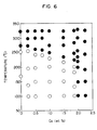
- Fig. 6 shows how the color of the foils were changed after heating followed by quenching.
- the solid circle mark represents pink color, while blank circle shows silver color.
- the threshold temperature at which the color is changed is about 275°C in the Ag-35 wt% Zn alloy containing no Cu and that the threshold temperature becomes lower as the Cu content of the alloy is increased.
- the Cu content is preferably not greater than 1.8 wt%.
- Fig. 7 shows the colors of the foils obtained when the foils which had changed the color into pink were heated at varying temperature below 250°C for 2 minutes followed by air cooling. In all cases, the color was changed from pink to silver color at temperatures below 200°C. This threshold temperature tends to become higher as the Cu content is increased.
- the change of color into pink caused by the quenching from the high temperature is considered as being attributable to the formation and preservation of the ⁇ ' phase, while the color change from pink to silver color is considered as being attributable to a phase change from ⁇ ' phase to ⁇ phase.
- Fig. 8 shows the spectral reflectance exhibited by the Ag-35 wt% Zn-1 wt% Cu alloy foil. Distinctive difference in reflectance is observed over whole wavelength region of the light except the range between 530 nm and 600 nm. The reversible changes of color between pink and silver color and consequent reversible changes in the spectral reflectance were stably effected by repetitional heating and cooling at 240°C and 200°C.
- the foil specimen which had been changed into silver color was locally heated by a lighter and then quenched.
- the heated and quenched portion changed its color into pink, with high distinction from the silver color background.
- a foil of pink color was locally heated and the heated portion of this foil changed its color into silver color.
- An An-35 wt% Zn-1 wt% Cu alloy was melted in an argon atmosphere and was solidified into the form of a columnar member of 120 mm diameter. Disks of 5 mm thick and 100 mm dia. were cut out from the columnar member and used as the targets for sputtering.
- the sputter evaporation deposition was conducted on hard glass substrates of about 26 mm in diameter and 1.2 mm in thickness using a DC-magnetron type system under the conditions of 200°C in substrate temperature and 150 mW in the sputtering power, so as to form a film of the above-mentioned alloy to a thickness of about 80 nm.
- the sputtering was conducted within the Ar gas atmosphere of 20 mTorr. After the sputtering of the alloy film, a protective film of Al2O3 or SiO2 was formed by RF sputtering on the film surface to a thickness of about 20 nm.
- the film showed silver color in the state after the sputtering, but the color was changed into pink as the film was subjected to 2-minute heating at 240°C followed by water cooling together with the substrate. The film was then subjected to 2-minute heating at 200°C followed by water cooling, so that the color was changed again to silver color.
- the film formed by spattering showed the same tendency of color change as the foil mentioned before.
- Operations for recording, regenerating and erasing informations were conducted by means of laser beams while using a film of Ag-35 wt% Zn-1 wt% Cu formed by sputtering in the same way as in the Example 8.
- a semiconductor laser wavelength of 830 nm
- an Ar laser wavelength of 488 nm
- the film was scanned with the laser beam while both the power of the laser beam and the beam diameter on the film surface were changed between 10 and 50 mW and between 1 and 10 um respectively, so that lines of pink color were formed in the film surface as a result of the scanning.
- the line width was changed between about 1 and 20 ⁇ m in accordance with the laser power.
- the film was scanned with the semiconductor laser beam transversely of the lines.
- the change in the spectral reflectance having occurred when the scanning laser beam traveled across the line was detected electrically as a change in D.C. voltage in the order of about 20%.
- the change in color was successfully changed into electric signal.
- Ag-35 wt% Zn-Sm alloys were formed into foils by melt-quenching method and changes in color and spectral reflectance were examined. More specifically, Ag-based starting alloys containing 35 wt% of Zn and 0.5 to 8.0 wt% of Sm were melted in an argon atmosphere and solidified in the form of bars of 4 mm dia. The bars were then cut into pieces weighing 5 to 10 g and the thus obtained pieces were used as the alloy for melt-quenching.
- the melt-quenching was conducted by making use of a single-roll type apparatus which is known per se. Namely, the alloy pieces were melted again in a quartz nozzle and the melt was poured onto the outer peripheral surface of a roll (300 mm dia.) rotating at a high speed, so as to form Ag-Zn-Sm alloy foils of 50 ⁇ m thick and 5 mm wide.
- the foils were heated in an electric oven at varying temperatures for 2 minutes followed by water cooling, and the changes in the color and spectral reflectance were examined.
- Fig. 9 shows how the color of the foils were changed after heating followed by quenching.
- the solid circle mark represents pink color, while blank circle shows gold color. The discrimination was possible until the Sm content was increased up to 8.0 wt%. However, when the Sm content exceeds 8.2 wt%, all the specimens changed the color into gold and, hence, became not disinguishable from one another in the temperature region illustrated.
- Fig. 10 shows the colors of the foils obtained when the foils which had changed the color into pink were heated at varying temperature below 250°C for 2 minutes followed by air cooling.
- the Ag-35 wt% Zn alloy containing no Sm showed a threshold temperature of about 130° for the color to be changed from pink to silver color. This threshold temperature tends to become lower as the Sm content is increased.
- the ⁇ phase of Ag-Zn alloy originally exhibits silver color but the color is changed to gold by addition of Sm.
- the change of color into, pink caused by the quenching from the high temperature is considered as being attributable to the formation and preservation of the ⁇ ' phase, while the color change from pink to gold is considered as being attributable to a phase change from ⁇ ' phase to ⁇ phase.
- Fig. 11 shows the spectral reflectance exhibited by the Ag-35 wt% Zn-3 wt% Sm alloy foil. Distinctive difference in reflectance is observed over whole wavelength region of the light except the range between 350 nm and 550 nm. The reversible changes of color between pink and gold and consequent reversible changes in the spectral reflectance were stably effected by repetitional heating and cooling at 275°C and 110°C.
- the foil specimen which had been changed into gold color was locally heated by a lighter and then quenched.
- the heated and quenched portion changed its color into pink, with high distinction from the gold color background.
- a foil of pink color was locally heated and the heated portion of this foil changed its color into gold.
- the sputter evaporation deposition was conducted on hard glass substrates of about 26 mm in diameter and 1.2 mm in thickness using a DC-magnetron type system under the conditions of 200°C in substrate tmeperature and 150 mW in the sputtering power, so as to form a film of the above-mentioned alloy to a thickness of about 80 nm.
- the sputtering was conducted within the Ar gas atmosphere of 20 mTorr. After the formation of the alloy film, a protective film of Al2O3 or SiO2 was formed by RF sputtering on the film surface to a thickness of about 20 nm.
- the film showed gold color in the state after the sputtering, but the color was changed into pink as the film was subjected to 2-minute heating at 275°C followed by water cooling together with the substrate. The film was then subjected to 2-minute heating at 110°C followed by water cooling, so that the color was changed again to gold color.
- the film formed by sputtering showed the same tendency of color change as the foil mentioned before.
- Operations for recording, regenerating and erasing informations were conducted by means of laser beams using a film of Ag-35 wt% Zn-3 wt% Sm formed by sputtering in the same way as the Example 11.
- a semiconductor laser wavelength of 830 nm
- an Ar laser wavelength of 488 nm
- the film of silver color was scanned with the laser beam while both the power of the laser beam and the beam diameter on the film surface were changed between 10 and 50 mW and between 1 and 10 ⁇ m respectively, so that lines of pink color were formed in the film surface as a result of the scanning.
- the line width was changed between about 1 and 20 ⁇ m in accordance with the laser power.
- the film was scanned with the semiconductor laser beam transversely of the lines.
- the change in the spectral reflectance occurred when the scanning laser beam travels across the line was detected electrically as a change in D.C. voltage in the order of about 20%.
- the change in color was successfully changed into electric signal.
- Ag-35 wt% Zn-Ga alloys were formed into foils by melt-quenching method and changes in color and spectral reflectance were examined. More specifically, Ag-based starting alloy containing 35 wt% of Zn and 0.1 to 4.0 wt% of Ga was melted in an argon atmosphere and solidified in the form of bars of 4 mm dia. The bars were then cut into pieces weighing 5 to 10 g and the thus obtained pieces were used as the alloy for melt-quenching.
- the melt-quenching was conducted by making use of a single-roll type apparatus which is known per se. Namely, the alloy pieces were melted again in a quartz nozzle and the melt was poured onto the outer peripheral surface of a roll (300 mm dia.) rotating at a high spped, so as to form Ag-Zn-Ga alloy foils of 50 ⁇ m thick and 5 mm wide.
- the foils were heated in an electric oven at varying temperatures for 2 minutes followed by water cooling, and the changes in the color and spectral reflectance were examined.
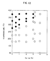
- Fig. 12 shows how the color of the foils were changed after heating followed by quenching.
- the solid circle mark represents pink color, while blank circle shows silver color.
- the threshold temperature at which the color is changed is about 275°C in the Ag-35 wt% Zn alloy containing no Ga and that the threshold temperature becomes higher as the Ga content of the alloy is increased.
- the Ga content exceeds 3.2 wt%, all the specimen changed the color into silver and, hence, became not distinguishable from one another in the temperature region illustrated.
- Fig. 13 shows the colors of the foils obtained when the foils which had changed the color into pink were heated at varying temperature below 200°C for 2 minutes followed by air cooling.
- the Ag-35 wt% Zn alloy containing no Ga showed a threshold temperature of about 135° for the color to be changed from pink to silver color. This threshold temperature tends to become lower as the Ga content is increased.
- the change of color into pink caused by the quenching from the high temperature is considered as being attributable to the formation and preservation of the ⁇ ' phase, while the color change from pink to silver is considered as being attributable to a phase change from ⁇ ' phase to ⁇ phase.
- Fig. 14 shows the spectral reflectance exhibited by the Ag-35 wt% Zn-1 wt% Ga alloy foil. Distinctive difference in reflectivity is observed over whole wavelength region of the light except the range between 400 nm and 600 nm. The reversible changes of color between pink and silver and consequent reversible changes in the spectral reflectance were stably effected by repetitional heating and cooling at 300°C and 100°C.
- the foil specimen which had been changed into silver color was locally heated by a lighter and then quenched.
- the heated and quenched portion changed its color into pink, with high distinction from the silver color background.
- a foil of pink color was locally heated and the heated portion of this foil changed its color into silver color.
- An Ag-35 wt% Zn-1 wt% Ga alloy was melted in an argon atmosphere and was solidified into the form of a columnar member of 120 mm diameter. Disks of 5 mm thick and 100 mm dia. were cut out from the columnar member and used as the targets for sputtering.
- the sputter evaporation deposition was conducted on hard glass substrates of about 26 mm in diameter and 1.2 mm in thickness using a DC-magnetron type system under the conditions of 200°C in substrate temperature and 150 mW in the sputtering power, so as to form a film of the above-mentioned alloy to a thickness of about 80 nm.
- the sputtering was conducted within the Ar gas atmosphere of 20 mTorr. After the formation of the alloy film, a protective film of Al2O3 or SiO2 was formed by RF sputtering on the film surface to a thickness of about 20 nm.
- the film showed silver color in the state after the sputtering, but the color was changed into pink as the film was subjected to 2-minute heating at 300°C followed by water cooling together with the substrate. The film was then subjected to 2-minute heating at 100°C followed by water cooling, so that the color was changed again to silver color.
- the film formed by sputtering showed the same tendency of color change as the foil mentioned before.
- Operations for recording, regenerating and erasing informations were conducted by means of laser beams using a film of Ag-35 wt% Zn-1 wt% Ga formed by sputtering in the same way as the Example 14.
- a semiconductor laser wavelength of 830 nm
- an Ar laser wavelength of 488 nm
- the film was scanned with the laser beam while both the power of the laser beam and the beam diameter on the film surface were changed between 10 and 50 mW and between 1 and 10 ⁇ m respectively, so that lines of pink color were formed in the film surface as a result of the scanning.
- the line width was changed between about 1 and 20 ⁇ m in accordance with the laser power.
- the film was scanned with the semiconductor laser beam transversely of the lines.
- the change in the spectral reflectance occurred when the scanning laser beam travels across the line was detected electrically as a change in D.C. voltage on the order of about 20%.
- the change in color was successfully changed into electric singal.
- the alloy and the recording medium of the invention exhibits reversible change in the color and spectral reflectance due to a phase change between different crystal phases, so that they can be used suitably as a recording materials which permit recording and erasion of informations.
Landscapes
- Chemical & Material Sciences (AREA)
- Engineering & Computer Science (AREA)
- Materials Engineering (AREA)
- Mechanical Engineering (AREA)
- Metallurgy (AREA)
- Organic Chemistry (AREA)
- Inorganic Chemistry (AREA)
- Optical Record Carriers And Manufacture Thereof (AREA)
- Thermal Transfer Or Thermal Recording In General (AREA)
Claims (14)
- Alliage possédant des coefficients de réflexion spectrale variables et une composition incluant 30 à 46 % en poids de Zn, 0,1 à 15 % en poids au total d'au moins un élément choisi dans le groupe incluant Li;Mg,Ca; Ti,Zr,Hf; V,Nb,Ta; Cr,Mo,W; Mn; Co,Rh,Ir,Fe,Ru,Os,Ni,Pd,Pt; Cu,Au; Cd; B,Al,Ga,In; C,Si,Ge,Sn,Pb; P,Sb,Bi; Y,La,Ce,Sm, Gd,Tb,Dy,Lu; le reste étant formé de Ag et d'éventuelles impuretés, ledit alliage pouvant posséder différentes structures cristallines, dont l'une est obtenue lorsque l'alliage est maintenu à l'état solide à une première température supérieure à la température ambiante et dont une autre est obtenue lorsque l'alliage est maintenu à l'état solide à une seconde température inférieure à ladite première température.
- Alliage possédant un coefficient de réflexion spectrale variable selon la revendication 1, dans lequel ledit alliage possède un composé intermétallique.
- Alliage possédant un coefficient de réflexion spectrale variable selon la revendication 1 ou 2, dans lequel ledit alliage est un matériau fin.
- Alliage possédant un coefficient de réflexion spectrale variable selon l'une quelconque des revendications 1 à 3, dans lequel ledit alliage possède des grains cristallins d'une taille non supérieure à 0,1 µm.
- Alliage possédant un coefficient de réflexion spectrale variable selon l'une quelconque des revendications 1 à 4, dans lequel ledit alliage possède la forme d'une pellicule mince, d'une feuille, d'une bande, d'une poudre ou d'un fil mince.
- Alliage possédant un coefficient de réflexion spectral variable selon l'une quelconque des revendications 1 à 5, possédant une composition incluant 30 à 46 % en poids de Zn, 0,1 à 10 % en poids de In, le reste étant formé de Ag et d'éventuelles impuretés.
- Alliage possédant un coefficient de réflexion spectrale variable selon la revendication 6, dans lequel la teneur en In est comprise entre 1,5 et 7,5 % en poids.
- Alliage possédant un coefficient de réflexion spectrale variable selon l'une des revendications 1 à 5, possédant une composition contenant 30 à 46 % en poids de Zn, 0,5 à 2,0 % en poids de Cu, le reste étant formé de Ag et d'éventuelles impuretés.
- Alliage possédant un coefficient de réflexion spectrale variable selon l'une quelconque des revendications 1 à 5, possédant une composition contenant 30 à 46 % en poids de Zn, 0,5 à 8,0 % en poids de Sm, le reste étant formé de Ag et d'éventuelles impuretés.
- Alliage possédant un coefficient de réflexion spectrale variable selon l'une quelconque des revendications 1 à 5, possédant une composition incluant 30 à 46 % en poids de Zn, 0,1 à 3,0 % en poids de Ga, le reste étant formé de Ag et d'éventuelles impuretés.
- Support d'enregistrement d'informations comprenant un alliage possédant un coefficient de réflexion spectrale variable et une composition contenant 30 à 46 % en poids de Zn, 0,1 à 15 % en poids au total d'au moins un élément choisi dans le groupe incluant Li;Mg,Ca; Ti,Zr,Hf; V,Nb,Ta; Cr,Mo,W; Mn; Co,Rh,Ir,Fe,Ru,Os,Ni,Pd,Pt; Cu,Au; Cd; B,Al,Ga,In; C,Si,Ge,Sn,Pb; P,Sb,Bi; Y,La,Ce,Sm, Gd,Tb,Dy,Lu; le reste étant formé de Ag et d'éventuelles impuretés, ledit alliage pouvant posséder différentes structures cristallines, dont l'une est obtenue lorsque l'alliage est maintenu à l'état solide à une première température supérieure à la température ambiante et dont une autre est obtenue lorsque l'alliage est maintenu à l'état solide à une seconde température inférieure à ladite première température.
- Support d'enregistrement d'informations selon la revendication 11, dans lequel ledit alliage possède une composition incluant 30 à 46 % en poids de Zn, 0,1 à 10 % en poids de In, le reste étant formé de Ag et d'éventuelles impuretés.
- Support d'enregistrement d'informations selon la revendication 11, dans lequel ledit alliage possède une composition incluant 30 à 46 % en poids de Zn, 0,5 à 2,0 % en poids de Cu, le reste étant formé de Ag et d'éventuelles impuretés.
- Support d'enregistrement d'informations selon la revendication 11, dans lequel ledit alliage possède une composition incluant 30 à 46 % en poids de Zn, 0,1 à 3,0 % en poids de Ga, le reste étant formé de Ag et d'éventuelles impuretés.
Applications Claiming Priority (2)
| Application Number | Priority Date | Filing Date | Title |
|---|---|---|---|
| JP255306/84 | 1984-12-03 | ||
| JP59255306A JPS61133349A (ja) | 1984-12-03 | 1984-12-03 | 分光反射率可変合金及び記録材料 |
Publications (3)
| Publication Number | Publication Date |
|---|---|
| EP0184412A2 EP0184412A2 (fr) | 1986-06-11 |
| EP0184412A3 EP0184412A3 (en) | 1988-07-20 |
| EP0184412B1 true EP0184412B1 (fr) | 1991-04-24 |
Family
ID=17276940
Family Applications (1)
| Application Number | Title | Priority Date | Filing Date |
|---|---|---|---|
| EP85308745A Expired EP0184412B1 (fr) | 1984-12-03 | 1985-12-02 | Alliage à réflectance spectrale variable et élément porteur d'informations en cet alliage |
Country Status (4)
| Country | Link |
|---|---|
| US (1) | US4743526A (fr) |
| EP (1) | EP0184412B1 (fr) |
| JP (1) | JPS61133349A (fr) |
| DE (1) | DE3582657D1 (fr) |
Families Citing this family (31)
| Publication number | Priority date | Publication date | Assignee | Title |
|---|---|---|---|---|
| BR8807352A (pt) * | 1987-02-13 | 1990-03-01 | Dow Chemical Co | Metodo para fabricar dispositivo de armazenamento de memoria otica e dispositivo de armazenamento otico |
| US5273861A (en) * | 1987-12-04 | 1993-12-28 | Matsushita Electric Industrial Co., Ltd. | Optical information recording medium, method of making an optical information recording medium and method of recording/reproducing optical information |
| JPH03169683A (ja) * | 1989-11-30 | 1991-07-23 | Toshiba Corp | 情報の記録及び消去方法 |
| US5328813A (en) * | 1992-06-30 | 1994-07-12 | The Dow Chemical Company | Method for the preparation of optical recording media containing overcoat |
| US6288842B1 (en) | 2000-02-22 | 2001-09-11 | 3M Innovative Properties | Sheeting with composite image that floats |
| US7068434B2 (en) | 2000-02-22 | 2006-06-27 | 3M Innovative Properties Company | Sheeting with composite image that floats |
| US7336422B2 (en) | 2000-02-22 | 2008-02-26 | 3M Innovative Properties Company | Sheeting with composite image that floats |
| SG116432A1 (en) * | 2000-12-26 | 2005-11-28 | Kobe Steel Ltd | Reflective layer or semi-transparent reflective layer for use in optical information recording media, optical information recording media and sputtering target for use in the optical information recording media. |
| US20020153625A1 (en) * | 2001-02-05 | 2002-10-24 | Pioneer Corporation | Stamper-forming electrode material, stamper-forming thin film, and method of manufacturing optical disk |
| JP3778425B2 (ja) * | 2001-10-03 | 2006-05-24 | 日立金属株式会社 | 表示装置に用いられる電子部品用Ag合金膜および表示装置に用いられる電子部品用Ag合金膜形成用スパッタリングターゲット材 |
| DE60305495T2 (de) * | 2002-06-28 | 2006-12-28 | Williams Advanced Materials Inc. | Korrosionsbeständige silbermetalllegierungen für optisches aufzeichnen und beschreibbare optische aufzeichnungsmedien welche diese legierung enthalten |
| US20040005432A1 (en) * | 2002-07-08 | 2004-01-08 | Ridout James W. | Reflective or semi-reflective metal alloy coatings |
| US7572517B2 (en) * | 2002-07-08 | 2009-08-11 | Target Technology Company, Llc | Reflective or semi-reflective metal alloy coatings |
| US7514037B2 (en) * | 2002-08-08 | 2009-04-07 | Kobe Steel, Ltd. | AG base alloy thin film and sputtering target for forming AG base alloy thin film |
| US7616332B2 (en) * | 2004-12-02 | 2009-11-10 | 3M Innovative Properties Company | System for reading and authenticating a composite image in a sheeting |
| JP2006294195A (ja) * | 2005-04-14 | 2006-10-26 | Kobe Steel Ltd | 光情報記録用Ag合金反射膜、光情報記録媒体および光情報記録用Ag合金反射膜の形成用のAg合金スパッタリングターゲット |
| JP2007002275A (ja) * | 2005-06-21 | 2007-01-11 | Toyoshima Seisakusho:Kk | 薄膜形成用材料、及びそれを用いて形成された薄膜並びにその形成方法 |
| US7981499B2 (en) * | 2005-10-11 | 2011-07-19 | 3M Innovative Properties Company | Methods of forming sheeting with a composite image that floats and sheeting with a composite image that floats |
| US7586685B2 (en) * | 2006-07-28 | 2009-09-08 | Dunn Douglas S | Microlens sheeting with floating image using a shape memory material |
| US20080027199A1 (en) | 2006-07-28 | 2008-01-31 | 3M Innovative Properties Company | Shape memory polymer articles with a microstructured surface |
| US7951319B2 (en) * | 2006-07-28 | 2011-05-31 | 3M Innovative Properties Company | Methods for changing the shape of a surface of a shape memory polymer article |
| US7800825B2 (en) * | 2006-12-04 | 2010-09-21 | 3M Innovative Properties Company | User interface including composite images that float |
| US8459807B2 (en) | 2007-07-11 | 2013-06-11 | 3M Innovative Properties Company | Sheeting with composite image that floats |
| CN103257379B (zh) * | 2007-11-27 | 2015-08-05 | 3M创新有限公司 | 形成具有悬浮合成图像的片材的母模 |
| US7995278B2 (en) * | 2008-10-23 | 2011-08-09 | 3M Innovative Properties Company | Methods of forming sheeting with composite images that float and sheeting with composite images that float |
| US8111463B2 (en) | 2008-10-23 | 2012-02-07 | 3M Innovative Properties Company | Methods of forming sheeting with composite images that float and sheeting with composite images that float |
| US9289962B2 (en) | 2011-05-20 | 2016-03-22 | 3M Innovative Properties Company | Laser-personalizable security articles |
| EP2710519B1 (fr) | 2011-05-20 | 2019-07-17 | Gemalto SA | Articles de sécurité personnalisés par laser |
| CA2857335A1 (fr) | 2011-12-15 | 2013-06-20 | 3M Innovative Properties Company | Objet de securite personnalise et methodes d'authentification d'un objet de securite et de verification d'un porteur d'un objet de securite |
| US10406845B2 (en) | 2013-03-15 | 2019-09-10 | Gemalto Sa | Flexible hinge material comprising cross-linked polyurethane material |
| US20140265301A1 (en) | 2013-03-15 | 2014-09-18 | 3M Innovative Properties Company | Security feature utlizing hinge material and biodata page |
Family Cites Families (6)
| Publication number | Priority date | Publication date | Assignee | Title |
|---|---|---|---|---|
| US3483531A (en) * | 1965-10-13 | 1969-12-09 | Rudnay Andre E De | Process for the recording,reproducing and erasing of information data on recording carriers |
| JPS607240B2 (ja) * | 1976-10-22 | 1985-02-22 | 大日本塗料株式会社 | 同時多層断層撮影用増感紙 |
| JPS5938291B2 (ja) * | 1981-02-25 | 1984-09-14 | 株式会社東芝 | 色調記憶素子用合金 |
| JPS619542A (ja) * | 1984-06-25 | 1986-01-17 | Hitachi Ltd | 記録材料及びその製造法 |
| JPS6137936A (ja) * | 1984-07-27 | 1986-02-22 | Hitachi Ltd | 分光反射率可変合金及び記録材料 |
| JPS61124541A (ja) * | 1984-11-21 | 1986-06-12 | Hitachi Ltd | 分光反射率可変合金及び記録材料 |
-
1984
- 1984-12-03 JP JP59255306A patent/JPS61133349A/ja active Pending
-
1985
- 1985-12-02 EP EP85308745A patent/EP0184412B1/fr not_active Expired
- 1985-12-02 DE DE8585308745T patent/DE3582657D1/de not_active Expired - Lifetime
- 1985-12-02 US US06/803,640 patent/US4743526A/en not_active Expired - Fee Related
Also Published As
| Publication number | Publication date |
|---|---|
| US4743526A (en) | 1988-05-10 |
| DE3582657D1 (de) | 1991-05-29 |
| EP0184412A3 (en) | 1988-07-20 |
| JPS61133349A (ja) | 1986-06-20 |
| EP0184412A2 (fr) | 1986-06-11 |
Similar Documents
| Publication | Publication Date | Title |
|---|---|---|
| EP0184412B1 (fr) | Alliage à réflectance spectrale variable et élément porteur d'informations en cet alliage | |
| EP0158804B1 (fr) | Appareil pour l'enregistrement et la reproduction d'information | |
| EP0136801B1 (fr) | Matériau d'enregistrement | |
| JPS6119747A (ja) | 分光反射率可変合金及び記録材料 | |
| JPS61190028A (ja) | 分光反射率可変合金および記録材料 | |
| JPS61195943A (ja) | 分光反射率可変合金及び記録材料 | |
| JPS6119752A (ja) | 分光反射率可変合金及び記録材料 | |
| JPS62112742A (ja) | 分光反射率可変合金 | |
| JPS61190033A (ja) | 分光反射率可変合金及び記録材料 | |
| JPS61190030A (ja) | 分光反射率可変合金および記録材料 | |
| JPS6046339A (ja) | 情報記録再生装置 | |
| JPS61133356A (ja) | 分光反射率可変合金及び記録材料 | |
| JPS61133352A (ja) | 分光反射率可変合金及び記録材料 | |
| JPS61190034A (ja) | 分光反射率可変合金及び記録材料 | |
| JPS61190032A (ja) | 分光反射率可変合金及び記録材料 | |
| JPH0530893B2 (fr) | ||
| JPS61110738A (ja) | 分光反射率可変合金及び記録材料 | |
| JPS61133350A (ja) | 分光反射率可変合金及び記録材料 | |
| JPS6176638A (ja) | 分光反射率可変合金及び記録材料 | |
| JPS6169934A (ja) | 分光反射率可変合金及び記録材料 | |
| JPS61133353A (ja) | 分光反射率可変合金及び記録材料 | |
| JPS6137936A (ja) | 分光反射率可変合金及び記録材料 | |
| JPS61133337A (ja) | 分光反射率可変合金及び記録材料 | |
| JPS61195949A (ja) | 分光反射率可変合金及び記録材料 | |
| JPS6230831A (ja) | 分光反射率可変合金及び記録材料 |
Legal Events
| Date | Code | Title | Description |
|---|---|---|---|
| PUAI | Public reference made under article 153(3) epc to a published international application that has entered the european phase |
Free format text: ORIGINAL CODE: 0009012 |
|
| 17P | Request for examination filed |
Effective date: 19860115 |
|
| AK | Designated contracting states |
Kind code of ref document: A2 Designated state(s): DE FR GB NL |
|
| PUAL | Search report despatched |
Free format text: ORIGINAL CODE: 0009013 |
|
| AK | Designated contracting states |
Kind code of ref document: A3 Designated state(s): DE FR GB NL |
|
| 17Q | First examination report despatched |
Effective date: 19900117 |
|
| GRAA | (expected) grant |
Free format text: ORIGINAL CODE: 0009210 |
|
| AK | Designated contracting states |
Kind code of ref document: B1 Designated state(s): DE FR GB NL |
|
| REF | Corresponds to: |
Ref document number: 3582657 Country of ref document: DE Date of ref document: 19910529 |
|
| ET | Fr: translation filed | ||
| PGFP | Annual fee paid to national office [announced via postgrant information from national office to epo] |
Ref country code: FR Payment date: 19911018 Year of fee payment: 7 |
|
| PGFP | Annual fee paid to national office [announced via postgrant information from national office to epo] |
Ref country code: GB Payment date: 19911122 Year of fee payment: 7 |
|
| PGFP | Annual fee paid to national office [announced via postgrant information from national office to epo] |
Ref country code: DE Payment date: 19920227 Year of fee payment: 7 |
|
| PLBE | No opposition filed within time limit |
Free format text: ORIGINAL CODE: 0009261 |
|
| STAA | Information on the status of an ep patent application or granted ep patent |
Free format text: STATUS: NO OPPOSITION FILED WITHIN TIME LIMIT |
|
| 26N | No opposition filed | ||
| PG25 | Lapsed in a contracting state [announced via postgrant information from national office to epo] |
Ref country code: GB Effective date: 19921202 |
|
| PGFP | Annual fee paid to national office [announced via postgrant information from national office to epo] |
Ref country code: NL Payment date: 19921231 Year of fee payment: 8 |
|
| GBPC | Gb: european patent ceased through non-payment of renewal fee |
Effective date: 19921202 |
|
| PG25 | Lapsed in a contracting state [announced via postgrant information from national office to epo] |
Ref country code: FR Effective date: 19930831 |
|
| PG25 | Lapsed in a contracting state [announced via postgrant information from national office to epo] |
Ref country code: DE Effective date: 19930901 |
|
| REG | Reference to a national code |
Ref country code: FR Ref legal event code: ST |
|
| PG25 | Lapsed in a contracting state [announced via postgrant information from national office to epo] |
Ref country code: NL Effective date: 19940701 |
|
| NLV4 | Nl: lapsed or anulled due to non-payment of the annual fee |