EP0185367A2 - Système de ceinture de sécurité - Google Patents
Système de ceinture de sécurité Download PDFInfo
- Publication number
- EP0185367A2 EP0185367A2 EP85116132A EP85116132A EP0185367A2 EP 0185367 A2 EP0185367 A2 EP 0185367A2 EP 85116132 A EP85116132 A EP 85116132A EP 85116132 A EP85116132 A EP 85116132A EP 0185367 A2 EP0185367 A2 EP 0185367A2
- Authority
- EP
- European Patent Office
- Prior art keywords
- clamping
- seat belt
- clamping part
- belt system
- webbing
- Prior art date
- Legal status (The legal status is an assumption and is not a legal conclusion. Google has not performed a legal analysis and makes no representation as to the accuracy of the status listed.)
- Granted
Links
- 230000007246 mechanism Effects 0.000 claims abstract description 35
- 230000033001 locomotion Effects 0.000 claims abstract description 28
- 238000004804 winding Methods 0.000 claims abstract description 8
- 230000001133 acceleration Effects 0.000 claims abstract description 7
- 230000000903 blocking effect Effects 0.000 claims description 15
- 239000000463 material Substances 0.000 claims description 11
- 230000005540 biological transmission Effects 0.000 claims description 4
- 239000004033 plastic Substances 0.000 claims description 4
- 230000001154 acute effect Effects 0.000 claims description 3
- 230000007423 decrease Effects 0.000 claims description 3
- 238000006073 displacement reaction Methods 0.000 claims description 3
- 125000006850 spacer group Chemical group 0.000 claims description 3
- 238000005452 bending Methods 0.000 claims description 2
- 230000007480 spreading Effects 0.000 claims description 2
- 238000003892 spreading Methods 0.000 claims description 2
- 239000002184 metal Substances 0.000 claims 1
- 238000005096 rolling process Methods 0.000 claims 1
- 230000000694 effects Effects 0.000 abstract description 17
- 238000013459 approach Methods 0.000 abstract description 2
- 230000001360 synchronised effect Effects 0.000 abstract description 2
- 238000013461 design Methods 0.000 description 11
- 229910000831 Steel Inorganic materials 0.000 description 6
- 239000010959 steel Substances 0.000 description 6
- 230000006870 function Effects 0.000 description 5
- 238000003860 storage Methods 0.000 description 5
- 238000000034 method Methods 0.000 description 4
- 230000008569 process Effects 0.000 description 4
- 238000011144 upstream manufacturing Methods 0.000 description 4
- 230000004913 activation Effects 0.000 description 3
- 238000002347 injection Methods 0.000 description 3
- 239000007924 injection Substances 0.000 description 3
- 239000011324 bead Substances 0.000 description 2
- 230000006835 compression Effects 0.000 description 2
- 238000007906 compression Methods 0.000 description 2
- 239000004744 fabric Substances 0.000 description 2
- 230000002349 favourable effect Effects 0.000 description 2
- 241001295925 Gegenes Species 0.000 description 1
- 206010039203 Road traffic accident Diseases 0.000 description 1
- 208000027418 Wounds and injury Diseases 0.000 description 1
- 230000009471 action Effects 0.000 description 1
- 230000006978 adaptation Effects 0.000 description 1
- XAGFODPZIPBFFR-UHFFFAOYSA-N aluminium Chemical compound [Al] XAGFODPZIPBFFR-UHFFFAOYSA-N 0.000 description 1
- 229910052782 aluminium Inorganic materials 0.000 description 1
- 230000008901 benefit Effects 0.000 description 1
- 238000010276 construction Methods 0.000 description 1
- 230000006735 deficit Effects 0.000 description 1
- 230000001627 detrimental effect Effects 0.000 description 1
- 238000011161 development Methods 0.000 description 1
- 238000005516 engineering process Methods 0.000 description 1
- 230000006698 induction Effects 0.000 description 1
- 238000009434 installation Methods 0.000 description 1
- 239000000314 lubricant Substances 0.000 description 1
- 238000004519 manufacturing process Methods 0.000 description 1
- -1 polytetrafluoroethylene Polymers 0.000 description 1
- 229920001343 polytetrafluoroethylene Polymers 0.000 description 1
- 239000004810 polytetrafluoroethylene Substances 0.000 description 1
- 238000003825 pressing Methods 0.000 description 1
- 230000035807 sensation Effects 0.000 description 1
- 230000035945 sensitivity Effects 0.000 description 1
- 210000002435 tendon Anatomy 0.000 description 1
- 238000012360 testing method Methods 0.000 description 1
- 230000001960 triggered effect Effects 0.000 description 1
Images


Classifications
-
- B—PERFORMING OPERATIONS; TRANSPORTING
- B60—VEHICLES IN GENERAL
- B60R—VEHICLES, VEHICLE FITTINGS, OR VEHICLE PARTS, NOT OTHERWISE PROVIDED FOR
- B60R22/00—Safety belts or body harnesses in vehicles
- B60R22/34—Belt retractors, e.g. reels
- B60R22/36—Belt retractors, e.g. reels self-locking in an emergency
- B60R22/42—Belt retractors, e.g. reels self-locking in an emergency having means for acting directly upon the belt, e.g. by clamping or friction
Definitions
- the invention relates to a seat belt system with a roll-up and locking mechanism having a sensor and control mechanism and a clamping device having a controlled clamping part for preventing further webbing withdrawal from the roll-up and locking mechanism, the clamping part operating with a relative movement of the roll-up and locking mechanism or a part of the same is coupled to the reel housing, for example a lifting or rotating movement of a reel spool, such that the clamping part can be moved in the clamping system by this relative movement.
- the seat belt of a seat belt system for example for motor vehicles, is provided with a retraction and locking mechanism, from which from the seat belt after passing through a deflection as a shoulder belt or possibly also as a lap belt on the body of a vehicle occupant, and is abruptly decelerated, for example, in the event of a traffic accident or another vehicle-related delay, the body of the vehicle occupant presses against the seat belt and strives to pull this off the spool of the reeling and locking mechanism. In this case, however, a rotational movement of the spool is prevented since the locking mechanism mentioned comes into action in a controlled manner with belt and / or vehicle sensitivity.
- a so-called “film reel effect” normally occurs, to the extent that the belt webbing can be withdrawn to a certain extent with the spool locked in the direction of rotation and the tensile load of the webbing webbing by the belt windings on the spool being pushed closer together.
- the webbing layers can move against each other until the webbing reel is firmly wound. This effect causes the seat belt to respond more slowly, which has a detrimental effect on the load of the occupants.
- the seat belt webbing starting from the spool, has already been placed around upstream deflection rollers which interact with a clamping jaw.
- this deflection has the disadvantage of increased friction, in particular when the seat belt is pulled off the spool for putting on the seat belt webbing.
- a clamping device in the area of the deflection fitting has also already been proposed (GB-PS 2 085 709).
- the clamping effect is the pressure exerted by the body of the vehicle occupant on the seat belt set in motion, the clamping part rotatably seated in an activated pivot lever.
- the most important performance feature of a clamp is extremely short belt pull-outs when the belt strap is subjected to a tensile force that exceeds the extent to which the belt strap can normally be pulled out of the belt strap storage for a corresponding comfort, for example to fasten the seat belt or when the seat belt is fastened perform certain movements to achieve controls in the motor vehicle.
- roll-up clamps ie clamps that work together with a roll-up and locking mechanism, are known for example from DE-OS 30 01 758, DE- O S 31 24 188 and DE-OS 33 30 938.
- the clamping part is movable in contact with the webbing itself, that the clamping blocking of the webbing by the clamping part only via the sensor and control mechanism directly and without the interposition of a certain load-absorbing pre-blocking can be initiated if the vehicle-sensitive acceleration exceeds a low limit value of, for example, approximately 0.45 g (CS) and belt-sensitive, a low limit value of, for example, approximately 1.5 g (WS).
- the invention proposes for the first time a roll-up clamp that no longer has any locking elements in the reel that transmit a certain load in the accident.
- the required resistance to initiate a clamping blockage through the belt pull-out is applied from the already existing sensor and control mechanical parts, which can consist of plastic parts and do not absorb any significant force.
- a clamping technology is thus realized for the first time which not only initiates a clamping block in an emergency, i.e. when there is an increased tensile load on the belt strap, but also the clamping mechanism at every deceleration of 0.45 g vehicle-sensitive (CS) and 1.5 g brings the webbing sensitive (WS) ready for clamping.
- CS vehicle-sensitive
- WS webbing sensitive
- the sensor for example a sensor ball, deflects and raises a control pawl. This alone ensures the readiness for clamping.
- the vehicle tilts into a ditch - the seat belt is pulled off by the shifting occupant.
- This belt strap pull-out now causes a stroke of the reel spool and thus a bringing up of the clamping part on the belt strap directly via the positively activated sensor and control mechanism.
- a return spring of the clamping part is set only so strongly in its spring force that said clamping blocking can be initiated immediately at the low acceleration values mentioned.
- a swivel lever which is arranged opposite the belt webbing and pressurized is expediently provided with a clamping part rotatably mounted therein.
- the clamping part can be rotatably supported in the swivel part with such frictional resistance that the clamping part assumes such an angular relative position to the swivel lever after the first application of its clamping surface to the swivel lever and maintains that the clamping part always by the entire clamping surface comes into contact with the webbing. This causes a gentle clamping intervention.
- the movable clamping part is provided with a large number of gripping teeth on its clamping surface.
- the clamping part can consist of a force-absorbing body and an upstream plate that carries the gripping teeth. This makes it possible to adapt the gripping surface to the respective conditions in terms of material, in particular with regard to the design of the gripping teeth, for example if this plate carrying the gripping teeth is produced as an injection molded part from a corresponding plastic material.
- the clamping part itself can then be made of such a material that can withstand the corresponding forces introduced.
- the tips of the gripping teeth are preferably directed towards the webbing surface in the direction opposite to the withdrawal direction, so that a particularly effective gripping of the gripping teeth is ensured. It is important for the effectiveness of the gripping process or the clamping process that the undercut surface of the gripping teeth encloses a special angle with the normal to the belt surface. This angle should preferably be 3 to 10 °.
- the gripping teeth can advantageously have an asymmetrical pyramid shape, and may the tips of the gripping teeth into the tooth rows offset one behind the other may be arranged, wherein the angle defined in Fig. 7 ⁇ is about 20 0th
- the design, orientation and arrangement of the gripping teeth are adapted to the respective structural structure of the webbing, in particular with the spacing of their rows of teeth to the position of the weft and warp threads of the woven webbing.
- the tooth row spacing corresponds to the spacing of the weft threads.
- the gripping teeth are aligned in a plane parallel to the belt webbing surface at an acute angle to the belt running direction, preferably at an angle of 20 degrees. If, in connection therewith, a space is provided perpendicular to the belt running direction in the plane of the clamping surface, this leads to a semi-positive locking of the teeth with the load-bearing warp threads, since the warp threads can meandle between the teeth and squeeze into the spaces.
- the width of the clamping surface occupied by the gripping teeth can be designed to decrease in the longitudinal direction of the webbing in a direction normal to the webbing running direction.
- the clamping part can have a material thinning at the edges, so that the clamping part adapts by bending at this point to the arching of the counter-pressure cheek that is ultimately unavoidable. This results in a more even application of force to the belt webbing at high load, combined with protection of the edges, whereby there is no tendency to engage at this point.
- a protruding strip made of rubber or the like material is inserted in the clamping surface of the clamping part provided with gripping teeth and extends in the belt running direction over the entire clamping surface.
- This bar first engages the webbing and is deformed with a certain amount of force so that the teeth themselves can engage.
- a particularly favorable intervention arises if, in connection therewith, the counter pressure surface faces the webbing is spherical. With high application of force, this crowning deforms so that a flat counter pressure surface comes into effect.
- the reel below the clamping mechanism does not contain any additional locking / blocking elements, but sensor activation is implemented directly by the control mechanism in a clamping or readiness to clamp.
- the belt is clamped so gently that, even after twenty thousand clamps, it is still able to take the full accident load in the crash.
- the movable or rotatably attached clamping part on the swivel lever and the swivel lever can be designed as aluminum injection molded parts or as plastic injection molded parts.
- the axis of rotation is formed as an integrated component of the movable clamping part or the pivoting lever and then a corresponding recess for receiving the axis of rotation is formed by the corresponding other part.
- the opening edge of the recess can then form the holding stop with a corresponding structural design.
- the axis of rotation is preferably a partially cylindrical rod and the recess is a correspondingly adapted, longitudinally slotted hollow cylinder which is open at at least one end.
- the parts can be easily connected to one another by inserting the part-cylindrical rod from the open side of the hollow cylinder into the latter along the axis of rotation. You save an axle as an extra component.
- the clamping part is provided with a convexly curved, spherical or partially cylindrical pivot bearing which is arranged opposite the clamping surface, which has a circumferential extent equal to or less than 180 degrees and engages with a concave, partially cylindrical pivot bearing surface of the pivot lever stands, one on
- the clamping part spring fixed on the pivot lever engages the clamping part.
- the clamping part spring can be guided around an engagement point on the clamping part and supported on a fixed housing point. This spring thus fulfills a double function and on the one hand it holds the clamping part together with the bearing surfaces mentioned.
- the spring serves as a release spring for the clamping part out of engagement with the webbing when the clamping is no longer desired.
- the spring holding the clamping part engages at a point on the clamping part which lies on the axis of rotation of the clamping part, then the spring does not exert any torque on the clamping part, so that the clamping part can assume the desired rotational position with a corresponding design of the frictional resistance between the clamping part and the pivot lever without being affected by the spring holding the clamping part on the swivel lever.
- a further embodiment of the invention is characterized in that the pivot lever is mounted by means of an axis in parallel housing walls without touching the same is and a center fixing projection is formed in a housing cover, which engages in a corresponding recess of the pivot lever, and that the axis is secured against axial displacement by the housing cover.
- pivot lever For a light and inexpensive design of the swivel lever and a simple one at the same time Installation of the pivot lever is further designed in such a way that the pivot lever has bearing journals integrally formed on both sides thereof, which are provided with bevels and can be snapped into corresponding bores of parallel housing walls by spreading apart the walls, and that these housing walls connect a spacer which is subsequently attached and the desired one Ensures distance.
- an actuating lever which is rotatably mounted on the housing is arranged between the roll-up and locking mechanism which triggers the mentioned movement of the pivoting lever and which in its rest position allows the operating lever to rotate freely Roll-up and locking mechanism allows.
- a corresponding transmission ratio can also be achieved through the design and arrangement of a plunger located on the pivot lever.
- webbing guide between the clamping part and the retraction and locking mechanism and on the side of the clamping part opposite the retraction and locking mechanism ensures that the webbing in Clamping area is guided in a very defined manner, regardless of the winding diameter or the webbing extension direction, so that it does not come into contact with the gripping teeth in the rest position.
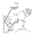
- the clamping device shown in Fig. 1 consists of a pivot lever 86 which is mounted on a pivot axis 90 fixed to the housing. At the end of the pivot lever 86 opposite the pivot axis, a clamping part 32 is rotatably mounted on an axis of rotation 84, which is pressed against a stop 92 of the pivot lever by a return spring 82 pressing on an extension 94 of the clamping part 32, and is thus held in a specific starting position. At the end of the pivot lever 86 opposite the stop 92 there is a control rod 46 which is actuated in the direction of the arrow in FIGS. 1 and 2 in order to bring the clamping part 32 into contact with the webbing 20. In the starting position, the clamping part 32 lies against a stop 77 which is at the same time designed as a guide for the belt strap.
- a counter pressure surface 60 formed by a bead 66 of the housing wall 64, which preferably has a surface with a particularly low coefficient of friction. This favors the loosening of the seat belt webbing 20 after a completed clamping process.
- a material band 68 is applied to the inside of the bead 66, which is, for example, a polytetrafluoroethylene band with a particularly low coefficient of friction.
- the clamping part 32 is provided on its clamping surface 72 with a plurality of gripping teeth 74.
- the initial rest position of the clamping part 32 shown in FIGS. 1 and 2 can be set so that in this rest position the clamping surface 72 to the belt webbing in the direction of the belt webbing assumes a presetting angle such that when the clamping part 32 is pivoted towards the belt webbing, the entire clamping surface with the gripping teeth in immediately Attachment to the webbing.
- the embodiment variant according to FIG. 2 differs from that in FIG. 1 in that the axis of rotation 84 is designed as a part-cylindrical integrated part 96 of the pivot lever 86, which is connected by a neck 98 to the actual body of the pivot lever 86.
- This neck 98 forms the stop, against which a stop surface 100 comes to rest.
- This stop surface 100 is formed by an opening slot edge 102 which delimits a hollow cylindrical recess 104.
- This hollow cylindrical recess 104 is open at at least one longitudinal end, so that the part-cylindrical axis of rotation 96 can be inserted into the recess from this side.
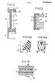
- FIG. 13 A special embodiment variant of the movable clamping part 32 is shown in FIG. 13.
- the clamping part is formed in two parts, namely the clamping part 32 consists of a force-absorbing base body 33 and an upstream tooth plate 35 with teeth 74. These teeth 74 are shown in more detail in FIGS. 14a, 14b and 15.
- the pivot lever 96 which is pivotable about the pivot axis 90, is provided with an integrated plunger 46 ′, which is normally at a distance of approximately 0.3 to 0.5 mm from the actuating coil 45 of the retractor so that it can be freely rotated when the webbing is pulled off when the pivoting lever bears against a stop 117 on the housing.
- the pivot lever 86 is provided with a concave, part-cylindrical recess 104 '. This recess is in engagement with a convex, partially cylindrical elevation of the clamping member 32, the circumferential extent of this circular, partially cylindrical elevation 96 being equal to or less than 180 degrees.
- the clamping part would therefore fall out of the recess 104 '.
- the clamping part is provided on both sides with a pin 103, around which a clamping part spring 112 is placed, which is fastened with one end 114 to the swivel lever and is supported with the other end 116 on a housing part 118.
- This support on the housing part causes a pretension in such a way that after clamping the pivot lever 86 can be released from the clamping engagement with the webbing.
- This spring therefore performs a double function.
- the convex design of the elevation 96 means that the clamping part can be aligned precisely with the belt strap or the clamping surface. It is self-adapting, especially when deformed under load.
- the embodiment according to FIG. 4 differs from that according to FIG. 3 in that not only is the clamping part spring l12 'fixed to the housing at another point, but that this spring also acts on the clamping part on an axle stub 103' where the axis of rotation 96 ' of the clamping part 32 is located.
- the clamping part spring 112 'performs only one function in that it holds the clamping part 32 in the depression 104' of the pivoting lever 86.
- Between the trough surface 104 'and the surface 96 of the clamping part there is such a friction that the clamping part 32 remains in the corresponding position after being rotated and then released, without the clamping part spring exerting an opposing torque on the clamping part.
- the movement induction on the pivot lever 86 is to take place in such a way that the clamping part 32 moves with respect to the movement component in the direction of pull of the belt strap when approaching the belt strap at the same speed as the belt strap.
- this synchronization effect there is no relative movement between the toothed gripping surface of the clamping part 32 and the belt strap, which has a very gentle engagement with the belt strap.
- the actuating element for interacting with the roll-up and locking mechanism 12 is not integrally connected to the pivoting lever 86, as is shown, for example, in FIG. 3.
- actuating levers 46 are pivotally mounted on the housing side in the bearing 172, the levers being connected to one another by a rod 174 shown in broken lines.
- the lever ratios can be set precisely by the configuration of this actuating lever.
- the actuating lever 170 remains in the basic position a play y of about 0.5 mm compared to the roll-up and locking mechanism, so that it can rotate freely in normal operation.
- the angle “illustrates the presetting angle of the clamping surface of the clamping part 32 in the starting position so that when Swiveling the clamping part against the webbing always brings the entire clamping surface into contact with the webbing.
- the angle of the swivel lever with the clamping part to the running direction of the belt is also important.
- the angle should be set in a range of approx. 20 to 40 degrees. It is the angle between the normal through the pivot axis of the pivot lever to the belt and the line through the pivot axis of the pivot lever and the clamping surface of the clamping part. If the angle is too large, there is no self-reinforcing effect and belt slip occurs. A very high friction in the clamping partial surface is required in order to achieve clamping at all, although there are no problems with deblocking and lower compressive forces are developed.
- FIG. 6 shows an example of a roll-up and locking mechanism as a belt storage device.
- the assembly of the control parts can be seen particularly well, the illustration being limited to a left "frame leg 180 and the left flange 45 of the shaft guided next to it.
- the belt retractor is shown in the rest position.
- a pulse lever 182 of the vehicle-sensitive sensor 184 (CS) is present the underside of a control pawl 186, which is in an external toothing 188 of a steering wheel 190 can intervene.
- the toothed ring of the shaft toothing which is present per se and which is otherwise in the rest position out of engagement with a toothing on the housing side is just as little present as the toothing on the housing side.
- a mechanical base plate 200 in which a bearing pin 202 is located as a fulcrum for a control disk 204, is shown in broken lines.
- the entire control disc 204 with the control wheel 190 guided therein and an intermediate control disc 204 and an inertia disc 206 arranged on the control wheel 190 is released after the locking between the control disc 204 and the control wheel 190, which can be triggered either by the vehicle-sensitive control pawl 186 or by a belt-sensitive pawl 208 can, in order to raise the bearing pins 202 in an elongated hole 210 in the mechanical base plate 200 from the rest position shown in FIG.
- the compression spring 212 clamped between the inertia disc 206 and the control wheel 190 in a corresponding recess ensures that in the rest position according to FIG. 6 the belt-sensitive pawl 208 remains out of engagement with an internal toothing 214 of the control disc 204. Only when the inertia disc 206 moves behind the movement of the Steering wheel 190 remains, overcoming the force of the compression spring 212, a relative movement between the inertia plate 206 and steering wheel 190 is achieved, by which the pawl by the mutual offset between a pin 216 on the inertia plate 206 and a bearing pin 218 on the steering wheel 190 to the outside Inner toothing 214 of the control disk 204 is pivoted.
- the belt retractor shown in FIG. 6 includes a vehicle-sensitive sensor with a ball 220 and a belt-strap-sensitive sensor, which can operate independently of one another.
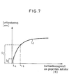
- the dash-dotted line b shows the conditions according to the prior art and the Dashed line a the situation in the present invention.
- the clamping takes place only with an increased webbing pull-out force, so that by the film reel effect a webbing pull-out of the order of magnitude S2 has taken place by then.
- the clamping takes place already at point a directly after the activation of the sensor and control parts without previous load-absorbing blocking in the retractor, so that only a webbing extension of the order of magnitude S1 occurs.
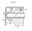
- the pivot lever 86 has a simple continuous axis 90 '. This axis is mounted on both sides, only one side being shown in FIG. 10, in openings 150 of the housing walls 152 which are essentially parallel to one another. Axis 90 'is axially secured by a housing cover 154 which, with ribs 156, prevents axial movement of the axis.
- the lid is also provided in the center with a centering projection 158 which engages in a centrally arranged, adapted recess 160 of the pivot lever 86. It is therefore not necessary to provide additional parts for fixing the position of the axis. 8, the pivot lever 86 is provided at both ends with a journal 90 ", which is cast on.
- This journal has a bevel 162, which is also pivotally mounted in openings 150 in the parallel housing walls 152.
- the Housing walls 152 spread apart a little, which is supported by the bevels 162 when the pivot lever 86 is inserted with its pin between the walls so that the journals 90 "snap into the openings 150.
- a spacer 164 is inserted between the walls after the pivoting lever 86 has been inserted.
- the space l64 formed by the bevel 162 can serve as a lubricant depot.
- a bushing 151 possibly a steel bushing, must be inserted between the opening 150 and the bearing journal 90 ". If this steel bushing is only inserted after the bearing journal 90" has snapped in, this leads to an easier assembly of the pivot lever 86.
- the storage conditions can be better designed by selecting the appropriate material for the bushing.
- the central position of the bar means that only one rubber bar needs to be installed. In any case, the webbing initially only comes into contact with the strip 120 and, after its deformation, only with the teeth of the clamping surface 72.
- a very effective clamping results from the fact that the opposite counter pressure surface 60 is slightly convex. With a correspondingly strong clamping force, this crowning deforms into a flat counter pressure surface.
- the crowning can be such that a crowning height h of 0.2 mm is present on the width of the counter pressure surface, as can be seen from FIG. 11a.
- the edges 122 of the webbing 20 protrude by an amount r beyond the lateral boundary of the clamping surface 72, so that the critical edges of the woven webbing 20 are not affected by the clamping pressure.
- the clamping part 32 has lateral deformable side zones 73 which can adapt to the deformation.
- FIG. 12 shows a special embodiment of the housing-applied part 62 ′ which forms the counter-pressure surface 60.
- This part 62 ' forms an inlet-side guide 70 and an outlet-side guide 70' for the belt, a side guide part 71 'for the belt extending between the two guides.
- the inlet slot is designated 71 and the outlet slot 71 '.
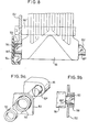
- FIGS. 14a, 14b and 15 show a special embodiment variant of the movable clamping part 32.
- the clamping part is formed in two parts, namely the clamping part 32 consists of a force-absorbing base body 33 and an upstream tooth plate 35 with the gripping teeth 74. These gripping teeth 74 are shown in FIGS. 14a, 14b and 15 are shown in more detail.
- the design of the gripping teeth is of particular importance for the effectiveness of a quick and gentle clamping engagement with the seat belt strap itself, both with regard to the choice of material and with regard to the dimensioning and arrangement of the gripping teeth.
- the gripping teeth are swept against the direction of movement of the seat belt webbing, i.e. the tips of the teeth are directed against the webbing withdrawal direction on the webbing surface.
- these gripping teeth have an asymmetrical pyramid shape.
- These pyramid-shaped gripping teeth are arranged in accordance with the illustration in FIG. 15 in such a way that the tooth tips in the rows of teeth are staggered one above the other. This takes place in particular in the adaptation to the special fabric structure of the seat belt webbing.
- the dimensioning of the gripping teeth is of particular importance. It has been found to be advantageous if the undercut surface 106 of the gripping teeth 74 forms an angle ⁇ of 3 ° to 10 ° with the normal 110 on the belt surface.
- the depth t of the tooth is approximately 2/3 of the webbing thickness and the tooth height h corresponds to the weft spacing of the woven webbing. This has the effect that the teeth engage between the warp and weft threads in a particularly favorable manner and thereby only slightly load the webbing fabric. This makes it possible for a frequent clamping intervention to take place without damaging the webbing.
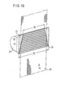
- D a is the force engagement between the clamping member 32 and clamping surface and the toothed portion in the belt withdrawal direction A at the outlet end of the clamping surface 72 is 74 at the largest and at the inlet end at its smallest, the clamping surface has as shown in Fig. Manner shown 16 preferably has a tapering in the belt withdrawal Width, the width on the inlet side preferably being somewhat larger than the width of the belt strap 20. If, for example, the belt strap has a width of 46 to 48 mm, the width on the inlet side should preferably be 50 mm and the width on the outlet side should be 30 mm. This configuration results in a more uniform stress on the belt and thus a higher load capacity.
- a number of approximately 400 gripping teeth are preferably used for the clamping part.
- the clamping surface has an extension of approx. 25 x 45 mm.
- the gripping teeth are aligned counter to the belt pull-off direction and in a plan view of the clamping surface plane of the clamping part 32 on a line parallel to the belt pull-off direction.
- the individual gripping teeth 74 are oriented at an acute angle cl of approximately 20 ° webbing running direction against the webbing take-off direction, only one tooth being shown in FIG. 17a.
- the teeth have the following dimensions.
- the dimension a is preferably approximately 1.7 mm, depending on the belt webbing, the dimension b approximately 1.5 mm and the dimension c approximately 0.6 to 0.8 mm.
- the tooth spacing c in FIG. 17b is approximately 1.5 mm, the tooth height h in the pulling direction of the webbing is approximately 1.7 mm according to FIG. 17c.
- the angle B in Fig. 17 c is preferably 60 ° and the tooth height t normal to the clamping surface is 0.8 mm, i.e. 2/3 of the webbing thickness.
- the tips are preferably rounded with a 0.1 mm radius.
- the tooth tip spacing in the pulling direction of the webbing depends on the spacing of the weft threads in the webbing, the warp threads in the longitudinal direction of the webbing and the weft threads running normally.
- the warp threads are the force-absorbing threads of the webbing.
- FIG. 18 shows yet another modified embodiment of the tooth arrangement with regard to a high load-bearing capacity, specifically as a function of the differentiated force attack already mentioned, according to which the teeth decrease in height with increasing proportion of force. From Fig. 18 it can be seen, for example, that the teeth located downstream in the pulling direction have an increasing height against the webbing pulling direction, namely from 0.5 mm to 0.6 mm, 0.7 mm for the first three rows of teeth and 0.8 mm constant for the remaining rows of teeth.
- the specified values correspond to approx. 40 % , 50%, 60% and 2/3 of the webbing thickness in the order mentioned.
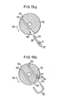
- FIGS. 19a and 19b show two possibilities for fastening the belt end in the core 124 of the spool 45 of the retractor.
- FIG. 19a A passage slot 128 is shown along an off-center tendon, which is provided with an extension 130 at the fastening end and is provided with a fillet 132 at the opposite end at the first deflection point of the webbing 20.
- the belt end 20 is threaded through the slot 128. The end is placed in a fold 20 'and fixed with a staple 21. Then the webbing end 20 is pulled into the extension 130 according to the arrow 134.
- the direction of rotation of the spool when the belt is pulled in is indicated by arrow 126.
- Such a definition is possible because the load is always taken up by the clamping parts.
- FIG. 19b Another embodiment variant results from FIG. 19b with two off-center slots 128 'and 129, slot 128' having a width of 2 mm and slot 129 having a width of 1.5 mm.
- the threading slot 128 essentially corresponds to the threading slot 128 of FIG. 19a and is likewise provided with a fillet 132 at the corresponding point.
- a toothing 136 set back by the belt thickness is provided between the slots.
- the webbing is inserted on the side into the threading slot 128 ', where the fillet 132 is provided. Then the webbing end 20 is inserted into the other slot 129 in accordance with arrow 140.
Landscapes
- Engineering & Computer Science (AREA)
- Mechanical Engineering (AREA)
- Automotive Seat Belt Assembly (AREA)
Applications Claiming Priority (4)
| Application Number | Priority Date | Filing Date | Title |
|---|---|---|---|
| DE3446857 | 1984-12-21 | ||
| DE3446857 | 1984-12-21 | ||
| DE3543959A DE3543959C2 (de) | 1984-12-21 | 1985-12-12 | Sicherheitsgurtaufroller mit Gurt-Klemmvorrichtung |
| DE3543959 | 1985-12-12 |
Related Child Applications (1)
| Application Number | Title | Priority Date | Filing Date |
|---|---|---|---|
| EP88118648.0 Division-Into | 1988-11-09 |
Publications (4)
| Publication Number | Publication Date |
|---|---|
| EP0185367A2 true EP0185367A2 (fr) | 1986-06-25 |
| EP0185367A3 EP0185367A3 (en) | 1987-08-19 |
| EP0185367B1 EP0185367B1 (fr) | 1990-04-04 |
| EP0185367B2 EP0185367B2 (fr) | 1993-03-24 |
Family
ID=25827629
Family Applications (2)
| Application Number | Title | Priority Date | Filing Date |
|---|---|---|---|
| EP88118648A Expired - Lifetime EP0310144B1 (fr) | 1984-12-21 | 1985-12-18 | Dispositif de serrage de sangle pour une ceinture de sécurité |
| EP85116132A Expired - Lifetime EP0185367B2 (fr) | 1984-12-21 | 1985-12-18 | Système de ceinture de sécurité |
Family Applications Before (1)
| Application Number | Title | Priority Date | Filing Date |
|---|---|---|---|
| EP88118648A Expired - Lifetime EP0310144B1 (fr) | 1984-12-21 | 1985-12-18 | Dispositif de serrage de sangle pour une ceinture de sécurité |
Country Status (5)
| Country | Link |
|---|---|
| US (1) | US4687253A (fr) |
| EP (2) | EP0310144B1 (fr) |
| DE (2) | DE3576941D1 (fr) |
| ES (1) | ES8704127A1 (fr) |
| SU (1) | SU1544179A3 (fr) |
Cited By (9)
| Publication number | Priority date | Publication date | Assignee | Title |
|---|---|---|---|---|
| EP0289320A1 (fr) * | 1987-05-01 | 1988-11-02 | Bsrd Limited | Rétracteur de ceinture de sécurité pour véhicule |
| WO1988009274A1 (fr) * | 1987-05-22 | 1988-12-01 | Ernst Hans Hellmut | Dispositif de serrage pour la sangle de ceintures de securite de vehicules a moteur |
| FR2629774A1 (fr) * | 1988-04-06 | 1989-10-13 | Autoflug Gmbh | Dispositif de retenue pour ceinture de securite |
| US4899949A (en) * | 1987-12-02 | 1990-02-13 | Bsrd Limited | Automatic safety-belt reeling device |
| FR2651734A1 (fr) * | 1989-09-11 | 1991-03-15 | Takata Corp | Enrouleur de ceinture de securite. |
| FR2656267A1 (fr) * | 1989-12-26 | 1991-06-28 | Takata Corp | Enrouleur de ceinture de securite. |
| EP0443764A1 (fr) * | 1990-02-22 | 1991-08-28 | Occupant Safety Systems Inc. | Enrouleurs automatiques pour ceintures de sécurité |
| DE4444655A1 (de) * | 1994-12-15 | 1996-06-20 | Autoliv Dev | Sicherheitsgurt-Blockiereinrichtung mit Selbstblockadeverhinderung |
| DE19539439A1 (de) * | 1995-10-24 | 1997-04-30 | Autoliv Dev | Sicherheitsgurtsystem mit einer beschleunigungsabhängig angesteuerten Klemmvorrichtung |
Families Citing this family (30)
| Publication number | Priority date | Publication date | Assignee | Title |
|---|---|---|---|---|
| DE3707056A1 (de) * | 1987-03-05 | 1988-09-15 | Ernst Hans Hellmut | Gurtklemmer-system |
| US4747617A (en) * | 1987-05-27 | 1988-05-31 | General Motors Corporation | Belt clamping guide loop |
| DE3740039A1 (de) * | 1987-11-26 | 1989-06-08 | Ernst Hans Hellmut | Klemmvorrichtung fuer einen sicherheitsgurt |
| EP0331119B1 (fr) * | 1988-02-29 | 1992-06-03 | Autoliv-Kolb GmbH & Co. | Dispositif de blocage de ceintures |
| KR900001552A (ko) * | 1988-07-27 | 1990-02-27 | 다까다 쥬우이찌로오 | 시이트 벨트 리트랙터 |
| US5029770A (en) * | 1988-09-30 | 1991-07-09 | Kabushiki Kaisha Tokai-Rika-Denki-Seisakusho | Webbing retractor |
| US4997140A (en) * | 1989-04-21 | 1991-03-05 | Occupant Safety Systems Inc. | Retractor with auxiliary brake mechanism |
| DE3931973C2 (de) * | 1989-09-25 | 2002-04-11 | Trw Repa Gmbh | Gurtband-Klemmeinrichtung |
| JPH07100431B2 (ja) * | 1990-06-28 | 1995-11-01 | タカタ株式会社 | シートベルトリトラクタ |
| JP2913789B2 (ja) * | 1990-08-01 | 1999-06-28 | タカタ株式会社 | シートベルトリトラクタ |
| JP2913790B2 (ja) * | 1990-08-01 | 1999-06-28 | タカタ株式会社 | シートベルトリトラクタ |
| JPH0810045Y2 (ja) * | 1990-08-31 | 1996-03-27 | 株式会社東海理化電機製作所 | ウエビング巻取装置 |
| JPH04151349A (ja) * | 1990-10-12 | 1992-05-25 | Takata Kk | シートベルトのクランプ装置 |
| ES2032368T1 (es) * | 1990-11-26 | 1993-02-16 | Trw Repa Gmbh | Dispositivo de retencion de cinturon de seguridad para vehiculos. |
| JPH04252761A (ja) * | 1991-01-28 | 1992-09-08 | Takata Kk | シートベルトリトラクタ |
| JPH04123861U (ja) * | 1991-04-25 | 1992-11-10 | 日本精工株式会社 | クランプ付リトラクター |
| US5316339A (en) * | 1991-05-31 | 1994-05-31 | Pacific Scientific Company | Safety belt gripping mechanism |
| DE9202219U1 (de) * | 1992-02-20 | 1992-05-21 | TRW Repa GmbH, 7077 Alfdorf | Sicherheitsgurt-Rückhaltesystem für Fahrzeuge |
| JP2574488Y2 (ja) * | 1992-09-07 | 1998-06-11 | 芦森工業株式会社 | シートベルトのリトラクター |
| US5350195A (en) * | 1993-01-28 | 1994-09-27 | Trw Vehicle Safety Systems Inc. | Device for clamping seat belt webbing |
| DE9305244U1 (de) * | 1993-04-06 | 1993-06-09 | TRW Repa GmbH, 7077 Alfdorf | Anordnung zur Befestigung eines Gurtbandes an einer Welle eines Sicherheitsgurtaufrollers |
| US5390977A (en) * | 1993-05-24 | 1995-02-21 | General Motors Corporation | D-ring for seat belt restraints |
| JPH0728753U (ja) * | 1993-11-04 | 1995-05-30 | 日本精工株式会社 | クランプ付リトラクター |
| US5511741A (en) * | 1994-09-30 | 1996-04-30 | Alliedsignal Inc. | Web clamping retractor mechanism with swinging housing |
| GB9509767D0 (en) * | 1995-05-15 | 1995-07-05 | Alliedsignal Ltd | Retractor |
| US6135561A (en) * | 1997-12-03 | 2000-10-24 | Ewald Witte Gmbh & Co. Kg | Seat back with headrest on vehicle seats |
| US6260884B1 (en) | 1999-03-05 | 2001-07-17 | Indiana Mills & Manufacturing, Inc. | D-loop web belt gripper |
| DE20020251U1 (de) * | 2000-11-29 | 2001-02-22 | Autoliv Development AB, Vårgårda | Kraftbegrenzerretractor mit darauf abgestimmtem Gurtband |
| US20090008494A1 (en) * | 2007-07-06 | 2009-01-08 | Maley William H | Spool assembly for dispensing a coil of wire |
| DE102011086656A1 (de) | 2011-11-18 | 2012-05-03 | Takata-Petri Ag | Sensor |
Family Cites Families (18)
| Publication number | Priority date | Publication date | Assignee | Title |
|---|---|---|---|---|
| US3814346A (en) * | 1965-10-20 | 1974-06-04 | M Carter | Retractable safety belt device |
| DE2234157A1 (de) * | 1972-07-12 | 1974-01-24 | Opel Adam Ag | Sicherheitsgurtsystem |
| DE2259692A1 (de) * | 1972-12-06 | 1974-06-12 | Daimler Benz Ag | Verzoegerungsabhaengige sperrvorrichtung fuer ein sicherheits-gurtband |
| US4323204A (en) * | 1978-05-15 | 1982-04-06 | Juichiro Takada | Belt clamps for vehicle passenger restraint belts |
| JPS5841977Y2 (ja) * | 1978-09-08 | 1983-09-22 | 三菱自動車工業株式会社 | シ−トベルト用リトラクタ装置 |
| CA1133868A (fr) * | 1979-01-22 | 1982-10-19 | Juichiro Takada | Serre-boucles pour ceintures de securite |
| DE3008299C2 (de) * | 1980-03-04 | 1987-04-23 | TRW Repa GmbH, 7077 Alfdorf | Aufrollautomat für einen Sicherheitsgurt |
| GB2085709A (en) | 1980-10-21 | 1982-05-06 | Klippan Nv Sa | Tensioning and locking system for safety belts |
| US4544112A (en) * | 1981-01-22 | 1985-10-01 | American Safety Equipment Corporation | Safety belt webbing emergency locking apparatus |
| DE3124188C2 (de) * | 1981-06-19 | 1986-04-03 | TRW Repa GmbH, 7077 Alfdorf | Gurtband-Klemmvorrichtung für Sicherheitsgurte in Kraftfahrzeugen |
| FR2511320A1 (fr) * | 1981-08-13 | 1983-02-18 | Klippan Nv | Montage d'enrouleur de sangle de ceinture de securite a deplacement relatif |
| US4451062A (en) * | 1981-08-20 | 1984-05-29 | American Safety Equipment Corporation | Automatic locking safety belt retraction apparatus with resetting means |
| US4429920A (en) * | 1981-09-04 | 1984-02-07 | General Motors Corporation | Load transfer system for seat mounted retractor |
| US4492348A (en) * | 1982-01-29 | 1985-01-08 | American Safety Equipment Corporation | Protractive force responsive safety belt locking apparatus |
| US4437623A (en) * | 1982-09-21 | 1984-03-20 | American Safety Equipment Corporation | Integrated weblocker with program pawl retractor |
| DE3421837A1 (de) * | 1984-02-16 | 1985-12-12 | Hans-Hellmut Dipl.-Ing. 2061 Sülfeld Ernst | Arretiervorrichtung fuer einen sicherheitsgurt |
| DE3412383A1 (de) * | 1984-02-25 | 1985-10-24 | Hans-Hellmut Dipl.-Ing. 2061 Sülfeld Ernst | Umlenkvorrichtung fuer einen sicherheitsgurt mit abgestufter gurtbandklemmung |
| DE3417877A1 (de) * | 1984-05-14 | 1985-11-14 | Britax-Kolb GmbH & Co, 8065 Erdweg | Sicherheitsgurtsystem |
-
1985
- 1985-12-18 DE DE8585116132T patent/DE3576941D1/de not_active Expired - Fee Related
- 1985-12-18 EP EP88118648A patent/EP0310144B1/fr not_active Expired - Lifetime
- 1985-12-18 EP EP85116132A patent/EP0185367B2/fr not_active Expired - Lifetime
- 1985-12-20 US US06/811,683 patent/US4687253A/en not_active Expired - Lifetime
- 1985-12-20 ES ES550209A patent/ES8704127A1/es not_active Expired
- 1985-12-20 SU SU853996107A patent/SU1544179A3/ru active
-
1986
- 1986-04-21 DE DE3613430A patent/DE3613430C2/de not_active Expired - Fee Related
Cited By (13)
| Publication number | Priority date | Publication date | Assignee | Title |
|---|---|---|---|---|
| US4938431A (en) * | 1987-05-01 | 1990-07-03 | Bsrd Limited | Vehicle seat belt retractor |
| EP0289320A1 (fr) * | 1987-05-01 | 1988-11-02 | Bsrd Limited | Rétracteur de ceinture de sécurité pour véhicule |
| US5029896A (en) * | 1987-05-22 | 1991-07-09 | Ernst Hans Hellmut | Clamping device for the belt band of motor vehicle safety belts |
| WO1988009274A1 (fr) * | 1987-05-22 | 1988-12-01 | Ernst Hans Hellmut | Dispositif de serrage pour la sangle de ceintures de securite de vehicules a moteur |
| US4899949A (en) * | 1987-12-02 | 1990-02-13 | Bsrd Limited | Automatic safety-belt reeling device |
| FR2629774A1 (fr) * | 1988-04-06 | 1989-10-13 | Autoflug Gmbh | Dispositif de retenue pour ceinture de securite |
| FR2651734A1 (fr) * | 1989-09-11 | 1991-03-15 | Takata Corp | Enrouleur de ceinture de securite. |
| FR2656267A1 (fr) * | 1989-12-26 | 1991-06-28 | Takata Corp | Enrouleur de ceinture de securite. |
| EP0443764A1 (fr) * | 1990-02-22 | 1991-08-28 | Occupant Safety Systems Inc. | Enrouleurs automatiques pour ceintures de sécurité |
| DE4444655A1 (de) * | 1994-12-15 | 1996-06-20 | Autoliv Dev | Sicherheitsgurt-Blockiereinrichtung mit Selbstblockadeverhinderung |
| US5588612A (en) * | 1994-12-15 | 1996-12-31 | Autoliv Development Ab | Safety belt blocking device with self-blocking prevention |
| DE19539439A1 (de) * | 1995-10-24 | 1997-04-30 | Autoliv Dev | Sicherheitsgurtsystem mit einer beschleunigungsabhängig angesteuerten Klemmvorrichtung |
| DE19539439C2 (de) * | 1995-10-24 | 2000-06-21 | Autoliv Dev | Klemmvorrichtung |
Also Published As
| Publication number | Publication date |
|---|---|
| US4687253A (en) | 1987-08-18 |
| EP0310144A2 (fr) | 1989-04-05 |
| ES8704127A1 (es) | 1987-03-16 |
| EP0185367B2 (fr) | 1993-03-24 |
| DE3613430C2 (de) | 1999-04-08 |
| SU1544179A3 (ru) | 1990-02-15 |
| DE3576941D1 (de) | 1990-05-10 |
| ES550209A0 (es) | 1987-03-16 |
| EP0185367B1 (fr) | 1990-04-04 |
| EP0310144A3 (en) | 1989-05-17 |
| DE3613430A1 (de) | 1987-10-22 |
| EP0310144B1 (fr) | 1992-09-30 |
| EP0185367A3 (en) | 1987-08-19 |
Similar Documents
| Publication | Publication Date | Title |
|---|---|---|
| EP0185367B1 (fr) | Système de ceinture de sécurité | |
| EP0173726B1 (fr) | Installation de renvoi pour une ceinture de securite avec blocage de ceinture etage | |
| DE2524874C3 (de) | Vorrichtung zum Absorbieren von Energie bei Kraftfahrzeug-Sitzgurten | |
| DE69608445T2 (de) | Sicherheitsgurtaufroller | |
| EP0556718B1 (fr) | Système de retenue par ceinture de sécurité pour véhicules | |
| EP0307822B1 (fr) | Dispositif de blocage de sangle pour une ceinture de sécurité à enrouleur | |
| EP0985847A2 (fr) | Dispositif de limitation de force | |
| DE19820641B4 (de) | Gurtaufwickeleinrichtung | |
| EP2277747A1 (fr) | Dispositif de verrouillage à renvoi | |
| DE2432956B2 (fr) | ||
| EP0487760A1 (fr) | Système de retenue par ceinture de sécurité pour véhicules | |
| DE3124188A1 (de) | Gurtband-klemmvorrichtung fuer sicherheitsgurte in kraftfahrzeugen | |
| DE3425199C1 (fr) | ||
| EP0186105B1 (fr) | Dispositif de blocage auto-sensible pour systèmes de ceintures de sécurité | |
| DE19514090C2 (de) | Anschnallgurt-Wickelvorrichtung | |
| DE3421837A1 (de) | Arretiervorrichtung fuer einen sicherheitsgurt | |
| DE3543959C2 (de) | Sicherheitsgurtaufroller mit Gurt-Klemmvorrichtung | |
| DE2733008A1 (de) | Sicherheitsgurtaufrollvorrichtung | |
| EP0257604B1 (fr) | Ferrure de renvoi à pince de blocage | |
| EP0856443B1 (fr) | Enrouleur de ceinture | |
| DE3717559C2 (fr) | ||
| DE3510673A1 (de) | Blockiereinrichtung fuer sicherheitsgurte | |
| DE10357812B4 (de) | Gurtspule für einen Sicherheitsgurtaufroller | |
| DE2122419C2 (de) | Aufwickelvorrichtung für einen Sicherheitsgurt | |
| DE2308895A1 (de) | Fahrzeugsitz mit verstellbarer rueckenlehne |
Legal Events
| Date | Code | Title | Description |
|---|---|---|---|
| PUAI | Public reference made under article 153(3) epc to a published international application that has entered the european phase |
Free format text: ORIGINAL CODE: 0009012 |
|
| AK | Designated contracting states |
Kind code of ref document: A2 Designated state(s): DE FR GB IT |
|
| PUAL | Search report despatched |
Free format text: ORIGINAL CODE: 0009013 |
|
| AK | Designated contracting states |
Kind code of ref document: A3 Designated state(s): DE FR GB IT |
|
| 17P | Request for examination filed |
Effective date: 19880114 |
|
| 17Q | First examination report despatched |
Effective date: 19881122 |
|
| RAP1 | Party data changed (applicant data changed or rights of an application transferred) |
Owner name: AUTOLIV-KOLB GMBH & CO. |
|
| GRAA | (expected) grant |
Free format text: ORIGINAL CODE: 0009210 |
|
| AK | Designated contracting states |
Kind code of ref document: B1 Designated state(s): DE FR GB IT |
|
| XX | Miscellaneous (additional remarks) |
Free format text: TEILANMELDUNG 88118648.0 EINGEREICHT AM 18/12/85. |
|
| ITF | It: translation for a ep patent filed | ||
| GBT | Gb: translation of ep patent filed (gb section 77(6)(a)/1977) | ||
| REF | Corresponds to: |
Ref document number: 3576941 Country of ref document: DE Date of ref document: 19900510 |
|
| ET | Fr: translation filed | ||
| PLBI | Opposition filed |
Free format text: ORIGINAL CODE: 0009260 |
|
| ITTA | It: last paid annual fee | ||
| PLBI | Opposition filed |
Free format text: ORIGINAL CODE: 0009260 |
|
| 26 | Opposition filed |
Opponent name: HS TECHNIK + DESIGN TECHNISCHE ENTWICKLUNGEN GMBH Effective date: 19901207 |
|
| 26 | Opposition filed |
Opponent name: AUTOFLUG GMBH & CO FAHRZEUGTECHNIK Effective date: 19901229 Opponent name: HS TECHNIK + DESIGN TECHNISCHE ENTWICKLUNGEN GMBH Effective date: 19901207 |
|
| REG | Reference to a national code |
Ref country code: GB Ref legal event code: 732 |
|
| PUAH | Patent maintained in amended form |
Free format text: ORIGINAL CODE: 0009272 |
|
| STAA | Information on the status of an ep patent application or granted ep patent |
Free format text: STATUS: PATENT MAINTAINED AS AMENDED |
|
| 27A | Patent maintained in amended form |
Effective date: 19930324 |
|
| AK | Designated contracting states |
Kind code of ref document: B2 Designated state(s): DE FR GB IT |
|
| GBTA | Gb: translation of amended ep patent filed (gb section 77(6)(b)/1977) |
Effective date: 19930303 |
|
| ET3 | Fr: translation filed ** decision concerning opposition | ||
| ITF | It: translation for a ep patent filed | ||
| REG | Reference to a national code |
Ref country code: GB Ref legal event code: IF02 |
|
| PGFP | Annual fee paid to national office [announced via postgrant information from national office to epo] |
Ref country code: FR Payment date: 20031210 Year of fee payment: 19 |
|
| PGFP | Annual fee paid to national office [announced via postgrant information from national office to epo] |
Ref country code: GB Payment date: 20031217 Year of fee payment: 19 |
|
| PGFP | Annual fee paid to national office [announced via postgrant information from national office to epo] |
Ref country code: DE Payment date: 20031229 Year of fee payment: 19 |
|
| PG25 | Lapsed in a contracting state [announced via postgrant information from national office to epo] |
Ref country code: GB Free format text: LAPSE BECAUSE OF NON-PAYMENT OF DUE FEES Effective date: 20041218 |
|
| PG25 | Lapsed in a contracting state [announced via postgrant information from national office to epo] |
Ref country code: DE Free format text: LAPSE BECAUSE OF NON-PAYMENT OF DUE FEES Effective date: 20050701 |
|
| GBPC | Gb: european patent ceased through non-payment of renewal fee |
Effective date: 20041218 |
|
| PG25 | Lapsed in a contracting state [announced via postgrant information from national office to epo] |
Ref country code: FR Free format text: LAPSE BECAUSE OF NON-PAYMENT OF DUE FEES Effective date: 20050831 |
|
| REG | Reference to a national code |
Ref country code: FR Ref legal event code: ST |