EP0192188A2 - Anordnung zur Positionierung einer in einer Kassette untergebrachten Aufnahmeplatte - Google Patents
Anordnung zur Positionierung einer in einer Kassette untergebrachten Aufnahmeplatte Download PDFInfo
- Publication number
- EP0192188A2 EP0192188A2 EP86101816A EP86101816A EP0192188A2 EP 0192188 A2 EP0192188 A2 EP 0192188A2 EP 86101816 A EP86101816 A EP 86101816A EP 86101816 A EP86101816 A EP 86101816A EP 0192188 A2 EP0192188 A2 EP 0192188A2
- Authority
- EP
- European Patent Office
- Prior art keywords
- disc
- recording
- supporting plate
- assembly
- cartridge
- Prior art date
- Legal status (The legal status is an assumption and is not a legal conclusion. Google has not performed a legal analysis and makes no representation as to the accuracy of the status listed.)
- Granted
Links
Images




Classifications
-
- G—PHYSICS
- G11—INFORMATION STORAGE
- G11B—INFORMATION STORAGE BASED ON RELATIVE MOVEMENT BETWEEN RECORD CARRIER AND TRANSDUCER
- G11B23/00—Record carriers not specific to the method of recording or reproducing; Accessories, e.g. containers, specially adapted for co-operation with the recording or reproducing apparatus ; Intermediate mediums; Apparatus or processes specially adapted for their manufacture
- G11B23/0014—Record carriers not specific to the method of recording or reproducing; Accessories, e.g. containers, specially adapted for co-operation with the recording or reproducing apparatus ; Intermediate mediums; Apparatus or processes specially adapted for their manufacture record carriers not specifically of filamentary or web form
- G11B23/0021—Record carriers not specific to the method of recording or reproducing; Accessories, e.g. containers, specially adapted for co-operation with the recording or reproducing apparatus ; Intermediate mediums; Apparatus or processes specially adapted for their manufacture record carriers not specifically of filamentary or web form discs
- G11B23/0028—Details
- G11B23/0035—Details means incorporated in the disc, e.g. hub, to enable its guiding, loading or driving
-
- G—PHYSICS
- G11—INFORMATION STORAGE
- G11B—INFORMATION STORAGE BASED ON RELATIVE MOVEMENT BETWEEN RECORD CARRIER AND TRANSDUCER
- G11B17/00—Guiding record carriers not specifically of filamentary or web form, or of supports therefor
- G11B17/02—Details
- G11B17/022—Positioning or locking of single discs
- G11B17/028—Positioning or locking of single discs of discs rotating during transducing operation
- G11B17/03—Positioning or locking of single discs of discs rotating during transducing operation in containers or trays
-
- G—PHYSICS
- G11—INFORMATION STORAGE
- G11B—INFORMATION STORAGE BASED ON RELATIVE MOVEMENT BETWEEN RECORD CARRIER AND TRANSDUCER
- G11B23/00—Record carriers not specific to the method of recording or reproducing; Accessories, e.g. containers, specially adapted for co-operation with the recording or reproducing apparatus ; Intermediate mediums; Apparatus or processes specially adapted for their manufacture
- G11B23/02—Containers; Storing means both adapted to cooperate with the recording or reproducing means
- G11B23/03—Containers for flat record carriers
- G11B23/033—Containers for flat record carriers for flexible discs
- G11B23/0332—Containers for flat record carriers for flexible discs for single discs, e.g. envelopes
Definitions
- the present invention relates to a disc cartridge for recording information in a recording disc and more particularly to a recording disc comprising a mechanism for positioning the recording disc with a high accuracy.
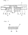
- Fig. 1 shows a part of a conventional magnetic recording disc of the type mentioned above, in which a magnetic disc assembly 2 for recording and reproducing information is rotatably assembled in a cartridge case 1.
- the magnetic disc assembly 2 is comprised of a magnetic disc 3 for recording of annular shape, a disc supporting plate 4 of annular shape made of stainless steel plate and having the magnetic disc 3 secured on the outer peripheral edge of the plate 4, a cylindrical hub 5 made of plastic resin material, being provided on the inner peripheral edge of the disc supporting plate 4 by outsert molding, and an annular regulating rib 6 projected from the disc supporting plate 4 near the outer peripheral area of the disc supporting plate 4.
- the recording disc 3 is made of a base film 3a of polyester film and magnetic layers 3b which may be formed one of the surface of the film 3a or formed on both surfaces as shown in Fig. 2.
- a disc drive assembly 8 of a disc drive device (not shown) is composed of a shaft 9, a disc supporting table 10 rotated with the shaft 9 and an annular permanent magnet 11 fitted to the disc supporting table 10
- the disc supporting plate 4 is secured on the top surface of the disc supporting table 10, the top surface of which serves as a reference surface, by the magnetic force of the permanent magnet 11.
- the inner part of the lower surface of the disc supporting plate 4 serves as a contacting surface for contacting the reference surface of the disc supporting table 10 and the outer part of the upper surface of the disc supporting plate 4 serves as a securing surface for securing the inner peripheral portion of the recording disc 3.
- the contacting surface and the securing surface are formed on both opposite surfaces of the disc supporting plate 4. Therefore, the securing surface changes relative to the contacting surface depending on the error of the thickness of the disc supporting plate 4, resulting in changing the position of the recording disc 3. Since the amount of movement of the recording head of the disc drive device to the recording disc is controlled based on the reference surface of the disc supporting table 10, if the recording disc 3 is displaced by the error of the thickness of the disc supporting plate 4, the contact pressure of the recording head to the recording disc 3 changes, thereby contact between the recording head and the recording disc become worse.
- the regulating rib 6 faces to the drive shaft insertion opening 12 of the cartridge case 1 so that the disc assembly 2 is prevented from being unduly displaced in the cartridge case 1 up to such extent that the recording disc is damaged by clash of the outer peripheral portion of the recording disc with the inner surface of the cartridge case 1 even if the disc cartridge is vibrated during transportation of the disc cartridge or the like.
- the hub core 5 is comprised of a V shaped regulating walls (not shown) in the drive shaft insertion opening 12 to center the drive shaft 9 relative to the center of the hub core 5.
- the disc supporting plate 4 is clamped on the reference surface of the disc supporting table 10 by the magnetic force of the permanent magnet 11 defining the vertical position of the disc assembly 2.
- the hub core 5 and the rib 6 are formed by separate members, the hub assembly being complicated in construction and therefore, reduction of the size and weight of the hub assembly is prevented.
- the magnetic pulling portion of the permanent magnet 11 is formed in the space between the outer peripheral portion of the hub core 5 and the rib 6, however, as the disc cartridge is made small, the space for the magnet must be also reduced, therefore size of the magnet 11 must be reduced, thereby resulting in reduction of the force of clamping the recording disc 3.
- the conventional disc drive apparatus is so arranged that the position of the disc assembly 2 in the disc drive device in the vertical direction is constrained by the top surface of the disc supporting table 10 and the disc assembly is centered by engagement between the cylindrical surface of the spindle 9 and the V shaped walls.
- the reference surfaces for positioning the disc assembly are made of combination of two individual members, therefore the reference surfaces change due to an error of size of each components per se and an assembling error, whereby a stable and accurate drive of the recording disc can not be assured.
- An essential object of the present invention is to provide a recording disc assembly which assures a good and reliable head contact.
- Another object of the present invention is to provide a recording disc cartridge which is able to reduce the size and thickness of the cartridge.
- a further object of the present invention to provide a disc drive device which is able to position a recording disc assembly in position with a high accuracy.
- a disc cartridge comprising;
- said recording disc assembly comprising recording disc, a contacting surface for detachably contacting with a reference surface of a disc drive device and a disc supporting plate having a disc securing surface to which an inner peripheral edge of the recording disc is secured thereby supporting the recording disc, said contacting surface and securing surface being situated on the same surface of the disc supporting plate.
- a disc drive device comprising; disc receiving means formed on the end portion of the spindle, the top face of the disc receiving means serving as a reference surface for defining the position of the recording disc in a thickness direction of the disc, and the outer surface of the disc receiving means serving as a reference surface of the recording disc in the radial direction of the recording disc.
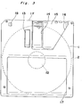
- a magnetic disc cartridge comprises a cartridge case 1, magnetic disc assembly 2 and a shutter movably mounted on the cartridge case 1.
- the cartridge case 1 is formed of a top half la and a bottom half 1b each being made of a generally flat and rectangular plate 1X (or 1Y) surrounded by vertical walls made of hard plastic resin materials such as ABS resin so that a generally thin flat square chamber to accommodate the disc assembly 2.
- Each of the top and bottom halves 1a and 1b is formed an elongated head insertion window 14 extending from near the central portion to near the front edge 1F of the cartridge case 1.
- the head insertion holes 12 are formed in the opposed position of the top and bottom halves la and 1b.
- the bottom half 1b is formed of a disc drive assembly insertion hole 12 of a round shape in the central portion of the cartridge case 1.
- Each of the top and bottom halves 1a and 1b is further formed of a recess 16 sank from the main surface of the cartridge case 1 with a generally trapezoid shape to which a shutter 15 is slidably mounted so as to closing and opening the head insertion hole 12 contained in the area of the recess 16. As shown in Fig.
- an elongated pressing member 13 is formed in parallel with said head insertion holes 12 on a portion of upper stream of rotation of the recording disc 3 in top half 1a for resiliently moving inward and outward of the top half 1a so as to slidably depress the recording disc 3 through a cleaning sheet 30 (see Fig. 4) made of non woven fabric and laid on the inner surface of the top half 1a.
- a label fitting area 17 is provided on the surface of the top half 1a in the rear half portion, to which a label (not shown) can be fitted.
- the disc assembly 2 rotatably accommodated in the chamber of the cartridge case 1 comprises the magnetic floppy disc 3 having an annular shape, a disc supporting plate 4 made of a stainless steel disc without any opening and a regulating rib 6 having a short and thin cylindrical shape formed by outsert molding so as coaxially to be secured to the lower surface of the disc supporting plate 4.
- the disc supporting plate may be made of other metallic flat plate.
- the disc supporting plate may be made of magnetic material.
- the regulating ring 6 may be formed of suitable plastic resin such as acetal resin.
- the inner peripheral portion of the recording disc 3 is fitted coaxially to the outer peripheral portion of the lower surface of the disc supporting plate 4.
- the lower surface of the disc supporting plate 4 acts as a reference surface which detachably contacts with the top face of a disc supporting table 10 of the disc drive assembly 8, whereby the upper surface of the recording disc 3 can be flush with the top surface or the reference surface of the disc supporting table 10.
- the position regulating rib 6 has an annular shape having its inner cylindrical surface formed V shaped walls 6a and 6b.
- Each of the walls 6a and 6b has a generally flat surface extending vertically and is disposed symmetrical with respect to the center line 0 of the regulating rib 6 on one half of the inner surface with respect to another center line P which is perpendicular to the first mentioned center line 0.
- the V shaped walls 6a and 6b are formed conforming to two tangent lines on a circle X corresponding to the outer cylindrical surface of the disc supporting table 10 of the disc drive device when the table 10 is placed coaxial with the regulating rib 6 the corner angle between both walls 6a and 6b is defined 45° to 120°.
- the disc assembly 2 can be centered with the disc drive assembly 8.
- the regulating rib 6 is secured to the disc supporting plate 4 by outsert molding. (In case the opening 4a of the disc supporting plate 4 is formed by rasing a part of the disc supporting plate 4 toward the reference surface of the disc supporting plate 4, then the mechanical strength of the regulating rib 6 can be reinforced.) It is noted that there tends to occur sagging 6' at the inner corner between the lower face of the disc supporting plate 4 and the inside of the regulating rib 6 to which the top portion of the disc drive assembly 8 is inserted.
- Fig. 7 shows a way of eliminating effect of the sagging 6', in which there are formed thick portions 6a' and 6b' (only 6b' is shown in Fig.
- a greater number of joints 4c are formed in the area where the walls 6a and 6b are formed relative to the number of the joints 4b in the side corresponding to the annular portion of the regulating rib 6 so that the amount of shrinkage in the walls 6a and 6b of the regulating rib 6 during molding is less than the amount of shrinkage in other part of the regulating ring 6 so as to prevent the decrement of the thickness of the walls 6a and 6b.
- the regulating rib 6 may serve to position the magnetic disc 3 in the radial direction.
- the regulating rib 6 is a rib centered with the center of the magnetic disc 3, the magnetic disc 3 can be positioned by fitting the regulating rib 6 in the central hole of the magnetic disc 3.
- the regulating rib 6 is not limited to a single continued annular shape but may be discontinued separately in the circumferential direction.
- a drive hole 7 is defined in a portion of the disc supporting plate 4 surrounded by the regulating ring 6.
- the drive hole 7 has an elongated shape along the center line P as shown in Fig. 5 so as to receive a drive pin 19 of the disc drive device.
- the disc drive assembly 8 comprises a rotational spindle 9 which is driven by a motor (not shown) of the disc drive device.
- the disc supporting table 10 in a generally saucer shape is fixed to the top of the spindle 9.
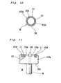
- the disc supporting table 10 has a round recess 10d surrounded by an annular peripheral wall 10e formed on the top portion of the disc supporting table 10 with the top annular surface 10a made flat to contact with the disc supporting plate 4.
- a permanent magnet 11 of a disc shape made of KS steel, MK steel, OP magnet, or ALNICO magnet contained in the recess 10d formed in the upper surface of the disc supporting table 10.
- a drive pin 19 is mounted on the disc supporting table 10 so as to move in the vertical direction between a position projected from the top surface of the disc drive member 10 as shown in Fig. 11 and a retracted position downwardly drawn from the top surface of the disc supporting table 10.
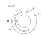
- the drive pin 19 is normally biased to the projected position by a resilient member 50 resiliently movably attached to the bottom face of the disc supporting table 10.
- the half of the outer peripheral portion of the resilient member 50 is made as a movable spring plate 52 separated by an arcuated cut portion 51.
- the lower end portion of the drive pin 19 is inserted into a round hole 53 defined in the movable spring plate 52 and secured thereto.
- the resilient member 50 is fitted to the lower surface of the disc supporting table 10 other than the movable spring plate 52 so that the spring plate 52 can be resiliently moved in the downward direction.
- the top surface 10a of the disc supporting table 10 is projected about 0.1 mm to 0.2 mm from the top surface of the permanent magnet 11 for positioning the disc assembly 2 in the disc drive device.
- the outer cylindrical surface 10b of the disc supporting table 10 serves to center the disc assembly 2 in association with the regulating rib 6 of the disc assembly 2.
- the outer diameter of the disc supporting table 10 is slightly smaller than the inner diameter of the regulating rib 6 and substantially equal to the diameter of the circle X shown in Fig. 5.
- the disc supporting plate 4 is fixedly placed on the top surface 10a of the disc supporting table 10 by the force of the magnet 11 for positioning the disc assembly 2 in the vertical direction. Also the disc assembly 2 is centered by the contact of the cylindrical surface 10b of the disc supporting table 10 with the flat walls 6a and 6b of the regulating rib 6 as shown in Fig. 4.
- the disc drive pin 19 When the disc assembly 2 is mounted on the disc supporting table 10, if the disc drive pin 19 is not inserted in the drive hole 7 of the disc supporting plate 4, the disc drive pin 19 is retracted from the upper surface of the disc supporting table 10 against the force of the resilient member 50. Subsequently when the disc drive pin 19 comes to the disc drive hole 7 upon rotation of the disc drive assembly 8, the disc drive pin 19 is projected into the disc drive hole 7 by the force of the spring plate 52 so that the rotation of the spindle 9 is transferred to the disc assembly 2, which is rotated.
- any engaging member such as a blind recess or projection may be used for engagement between the disc supporting plate 4 and the disc drive assembly 8.
- the drive hole 7 is formed an elongated arcuate shape as shown in Fig. 12a, it is possible to engage the drive pin 19 in the drive hole 7, ensuring to start rotation of the disc assembly 2 rapidly.
- the drive hole 7 may be formed with the length b larger than twice the diameter d of the drive pin 19 as shown in Fig. 12(b).
- the value b/d may be selected 2.0 to 3.0.
- the shape of the drive hole 7 is not limited to a square but may be selected in the desired shape such as a trapezoidal shape.
- the present invention is described with reference to the embodiment of the magnetic recording disc, the present invention can be applied to optical recording disc or the like.
- the permanent magnet is used as the mechanism for clamping the disc assembly 2, any other clamp mechanism may be used.
- a through hole is defined on the upper portion of the disc supporting plate 4 corresponding to the drive shaft insertion hole 12, so that the disc assembly 2 is clamped by a clamping means entered to the disc supporting plate 4 through the through hole.
- the magnetic drawing portion i.e., the permanent magnet 11 in the example shown, can be expanded as large as possible without limitation of the size of the spindle so as to increase the clamping force, thereby enabling to prevent wearing of the flat walls 6a and 6b of the regulating rib 6.
- the outer surface of the disc supporting table 10 is a cylindrical shape, the disc supporting table 10 may have a generally square shape in top plan view.
- the top end portion of the drive pin 19 is projected through the disc supporting plate 4 toward the inner surface of the top half 1a, in case the top half 1a is deformed, there may occur undesired clash of the drive pin'19 with the top half during rotation of the drive pin 19, thereby resulting in bad effects on rotation of the disc assembly 2 and wearing of the case body in addition to occurrence of error of reading and/or writing of the information in the recording disc.
- a spacer may be formed on any of the top half 1a or disc assembly 2 to develop a gap therebetween.
- Figs. 14 through 16 show one embodiment therefore, in which there is formed a projection 20 on the disc supporting plate 4 upside in the central portion.
- the top end of the projection 20 is close to the inner surface of the top half but not contacts thereto when assembled.
- the level of the top end of the projection 20 when assembled is so defined that there can be maintained a space 23 with at least length D between the lower surface of the of the disc supporting plate 4 and the inner surface of the top half 1a so as to prevent clash of the top end of the drive pin 19 with the inner surface of the top half 1a.
- the projection 20 is formed of a hollow semi spherical shape so that only the top end point contacts with the inner surface of the top half 1a even if the top half 1a is deformed for assuring a smooth rotation of the disc assembly 2.
- Fig. 17 shows a modification of the mechanism for preventing clash of the disc supporting plate 4 with the top half 1a in which a projection 21 similar to the projection 11 is formed on the top half 1a downward.
- the vertical length of the projection 21 is so defined that the length D of the space 23 can be maintainedfor preventing engagement of the disc supporting plate 4 with the top half 1a.
- Fig. 18 shows a further modification of the mechanism for preventing the engagement between the disc supporting plate 4 and top half 1a in which a plurality of projections 22 are formed on the upper surface of the disc supporting plate 4 i.e., the surface opposite to the surface on which regulating rib 6, in other word the surface facing to the inner surface of the top half 1a, generally along the line X (see Fig. 5) which corresponds to the circle of the regulating rib 6.
- the projections 22 may be formed independent of the regulating rib 6. However, the projections may be formed integral with the regulating rib 6 by projecting foot portions of the regulating rib 6 toward the opposite side of the disc supporting plate 4 through the openings 4b and 4c provided for securing the rib 6 to the disc supporting plate 4. This method may be effective to simplify the work of making the projections 22.
- the position of the projections 22 may be selected as desired on the upper surface of the disc supporting plate 4. Also the projections may be formed on the inner surface of the top half 1a.
- Fig. 19 shows a further embodiment of the disc cartridge according to the present invention in which the disc assembly 2 is formed in a similar manner as shown in Fig. 1 except for that the recording disc 3 is secured to the lower surface of the disc supporting plate 4 so that the surface of the recording disc 4 coincides with the top surface of the disc supporting table 10.
Landscapes
- Holding Or Fastening Of Disk On Rotational Shaft (AREA)
Applications Claiming Priority (8)
| Application Number | Priority Date | Filing Date | Title |
|---|---|---|---|
| JP60027548A JPS61188773A (ja) | 1985-02-16 | 1985-02-16 | デイスク駆動装置 |
| JP27548/85 | 1985-02-16 | ||
| JP27547/85 | 1985-02-16 | ||
| JP60027547A JPS61188790A (ja) | 1985-02-16 | 1985-02-16 | デイスクカ−トリツジ |
| JP60053297A JPH0740414B2 (ja) | 1985-03-19 | 1985-03-19 | 磁気デイスク体 |
| JP53297/85 | 1985-03-19 | ||
| JP60197748A JPS6258474A (ja) | 1985-09-09 | 1985-09-09 | デイスクカ−トリツジ |
| JP197748/85 | 1985-09-09 |
Publications (3)
| Publication Number | Publication Date |
|---|---|
| EP0192188A2 true EP0192188A2 (de) | 1986-08-27 |
| EP0192188A3 EP0192188A3 (en) | 1988-04-06 |
| EP0192188B1 EP0192188B1 (de) | 1991-05-29 |
Family
ID=27458708
Family Applications (1)
| Application Number | Title | Priority Date | Filing Date |
|---|---|---|---|
| EP86101816A Expired - Lifetime EP0192188B1 (de) | 1985-02-16 | 1986-02-13 | Anordnung zur Positionierung einer in einer Kassette untergebrachten Aufnahmeplatte |
Country Status (4)
| Country | Link |
|---|---|
| US (2) | US4743994A (de) |
| EP (1) | EP0192188B1 (de) |
| KR (1) | KR940009470B1 (de) |
| DE (1) | DE3679416D1 (de) |
Cited By (11)
| Publication number | Priority date | Publication date | Assignee | Title |
|---|---|---|---|---|
| EP0245507A4 (de) * | 1985-10-21 | 1988-06-23 | Seiko Epson Corp | Speicher/regeneratives gerät für plattenpatrone. |
| EP0277809A1 (de) * | 1987-02-02 | 1988-08-10 | Sony Corporation | Plattenkassette |
| EP0278358A1 (de) * | 1987-02-06 | 1988-08-17 | Sony Corporation | Platte für Aufzeichnungs- und/oder Wiedergabegerät mit magnetischer Klemmvorrichtung |
| EP0301866A3 (de) * | 1987-07-31 | 1990-02-28 | Mitsui Petrochemical Industries, Ltd. | Verfahren zur Herstellung einer magnetischen Nabe |
| EP0492651A3 (en) * | 1990-12-28 | 1993-01-20 | Sony Corporation | Optical disk and disk chucking mechanism |
| EP0498608A3 (en) * | 1991-02-05 | 1993-09-01 | Hoechst Celanese Corporation | Flexible magnetic disc cassettes with integrally molded wear button |
| EP0497604A3 (en) * | 1991-01-31 | 1993-10-13 | Sony Corporation | Disc cartridge |
| WO1997005615A1 (en) * | 1995-07-28 | 1997-02-13 | Minnesota Mining And Manufacturing Company | Recording disc cartridge having centrally-located, integral, raised wear-surface |
| US5768253A (en) * | 1992-05-15 | 1998-06-16 | Cd Plant Tecval S.A. | Disc cartridge for accommodating recording discs |
| US6038206A (en) * | 1991-02-07 | 2000-03-14 | Sony Corporation | Disc table for disc recording/reproducing apparatus and method for producing same |
| EP0553034B1 (de) * | 1992-01-24 | 2001-09-26 | Sony Corporation | Plattensteller für Plattenaufzeichnungs-/Wiedergabegerät |
Families Citing this family (10)
| Publication number | Priority date | Publication date | Assignee | Title |
|---|---|---|---|---|
| JPH01227281A (ja) * | 1988-03-08 | 1989-09-11 | Hitachi Maxell Ltd | デイスクカートリツジ及びデイスク駆動装置 |
| EP0449517B1 (de) * | 1990-03-27 | 1996-05-22 | Sony Corporation | Optische Platte |
| US5226033A (en) * | 1990-03-27 | 1993-07-06 | Sony Corporation | Magneto-optical disk hub in which the inner peripheral edge portion of the spindle opening is strengthened and made abrasion resistant |
| JP3498099B2 (ja) * | 1993-04-27 | 2004-02-16 | ソニー株式会社 | 記録媒体ディスク |
| JP3512533B2 (ja) * | 1995-08-30 | 2004-03-29 | 日立マクセル株式会社 | ディスク状記録媒体 |
| US5631792A (en) * | 1995-09-13 | 1997-05-20 | Imation Corp. | Triangle-shaped movable shutter for data storage diskette cartridge |
| USD381643S (en) * | 1995-09-13 | 1997-07-29 | Imation Corp. | Data storage diskette cartridge |
| USD381644S (en) * | 1995-09-13 | 1997-07-29 | Imation Corp. | Triangle-shaped movable shutter for a data storage diskette cartridge |
| JP2004110928A (ja) * | 2002-09-18 | 2004-04-08 | Fuji Photo Film Co Ltd | ディスクカートリッジ |
| EP1598814A4 (de) * | 2003-02-19 | 2006-03-22 | Neomax Co Ltd | Magnetfeldinterne wärmebehandlungseinrichtung |
Family Cites Families (8)
| Publication number | Priority date | Publication date | Assignee | Title |
|---|---|---|---|---|
| US4216511A (en) * | 1977-11-03 | 1980-08-05 | Texas Instruments Incorporated | Flexible magnetic recording disc with cartridge having a latching drive member |
| JPS5736473A (en) * | 1980-08-14 | 1982-02-27 | Sony Corp | Rotating driving device |
| JPS606938Y2 (ja) * | 1980-08-14 | 1985-03-07 | ソニー株式会社 | 記録再生用デイスクカセツト |
| JPS5835181U (ja) * | 1981-08-31 | 1983-03-07 | ソニー株式会社 | ディスクカセット |
| US4480282A (en) * | 1982-02-22 | 1984-10-30 | Verbatim Corporation | Stabilized locating ring for a flexible disk |
| JPS5971487U (ja) * | 1982-10-29 | 1984-05-15 | ソニー株式会社 | 磁気デイスクの回転装着台 |
| DE3415412A1 (de) * | 1983-04-25 | 1984-12-20 | Canon K.K., Tokio/Tokyo | Aufzeichnungs- oder wiedergabevorrichtung |
| JPS60147962A (ja) * | 1984-01-10 | 1985-08-05 | Toshiba Corp | フロツピ−デイスク装置 |
-
1986
- 1986-01-31 KR KR1019860000659A patent/KR940009470B1/ko not_active Expired - Fee Related
- 1986-02-13 DE DE8686101816T patent/DE3679416D1/de not_active Expired - Lifetime
- 1986-02-13 EP EP86101816A patent/EP0192188B1/de not_active Expired - Lifetime
- 1986-02-14 US US06/829,217 patent/US4743994A/en not_active Expired - Lifetime
-
1988
- 1988-01-29 US US07/150,300 patent/US4831478A/en not_active Expired - Lifetime
Cited By (17)
| Publication number | Priority date | Publication date | Assignee | Title |
|---|---|---|---|---|
| EP0245507A4 (de) * | 1985-10-21 | 1988-06-23 | Seiko Epson Corp | Speicher/regeneratives gerät für plattenpatrone. |
| EP0277809A1 (de) * | 1987-02-02 | 1988-08-10 | Sony Corporation | Plattenkassette |
| US4847826A (en) * | 1987-02-02 | 1989-07-11 | Sony Corporation | Disk cartridge |
| EP0278358A1 (de) * | 1987-02-06 | 1988-08-17 | Sony Corporation | Platte für Aufzeichnungs- und/oder Wiedergabegerät mit magnetischer Klemmvorrichtung |
| US4829510A (en) * | 1987-02-06 | 1989-05-09 | Sony Corporation | Disk for recording and/or reproducing apparatus having magnetic chucking device |
| EP0301866A3 (de) * | 1987-07-31 | 1990-02-28 | Mitsui Petrochemical Industries, Ltd. | Verfahren zur Herstellung einer magnetischen Nabe |
| US5020207A (en) * | 1987-07-31 | 1991-06-04 | Mitsui Petrochemical Industries, Ltd. | Process for producing magnetic hub |
| US5666347A (en) * | 1990-12-28 | 1997-09-09 | Sony Corporation | Optical disk and disk chucking mechanism |
| EP0492651A3 (en) * | 1990-12-28 | 1993-01-20 | Sony Corporation | Optical disk and disk chucking mechanism |
| KR100268618B1 (ko) * | 1990-12-28 | 2000-10-16 | 이데이 노부유끼 | 광학디스크 및 디스크 척킹 기구 |
| EP0497604A3 (en) * | 1991-01-31 | 1993-10-13 | Sony Corporation | Disc cartridge |
| EP0498608A3 (en) * | 1991-02-05 | 1993-09-01 | Hoechst Celanese Corporation | Flexible magnetic disc cassettes with integrally molded wear button |
| US6038206A (en) * | 1991-02-07 | 2000-03-14 | Sony Corporation | Disc table for disc recording/reproducing apparatus and method for producing same |
| EP0553034B1 (de) * | 1992-01-24 | 2001-09-26 | Sony Corporation | Plattensteller für Plattenaufzeichnungs-/Wiedergabegerät |
| US5768253A (en) * | 1992-05-15 | 1998-06-16 | Cd Plant Tecval S.A. | Disc cartridge for accommodating recording discs |
| US6125102A (en) * | 1992-05-15 | 2000-09-26 | Cd Plant Tecval S.A. | Disc cartridge with removal protector member |
| WO1997005615A1 (en) * | 1995-07-28 | 1997-02-13 | Minnesota Mining And Manufacturing Company | Recording disc cartridge having centrally-located, integral, raised wear-surface |
Also Published As
| Publication number | Publication date |
|---|---|
| US4831478A (en) | 1989-05-16 |
| EP0192188A3 (en) | 1988-04-06 |
| EP0192188B1 (de) | 1991-05-29 |
| KR860006778A (ko) | 1986-09-15 |
| KR940009470B1 (ko) | 1994-10-13 |
| DE3679416D1 (de) | 1991-07-04 |
| US4743994A (en) | 1988-05-10 |
Similar Documents
| Publication | Publication Date | Title |
|---|---|---|
| US4743994A (en) | Arrangement for positioning a recording disc of a disc cartridge | |
| EP0133541B1 (de) | Kassette für Aufzeichnungsplatte | |
| EP0116471B1 (de) | Flexible Magnetscheiben | |
| CA1190319A (en) | Flexible magnetic disk cassette and a recording and/or reproducing apparatus for the same | |
| EP0097363B1 (de) | Rotierende Platte | |
| EP0499413B1 (de) | Platte und Plattenklemmvorrichtung | |
| CA1284380C (en) | Disk cartridge | |
| EP0226378B1 (de) | Datenspeicherplattengerät | |
| US6160680A (en) | Two-piece media hub and methods of attaching same to a medium | |
| JP2580590B2 (ja) | デイスク回転駆動装置 | |
| US5973893A (en) | Magnetic disk cartridge in which shell halves are accurately positioned and process for producing the same | |
| JP3208806B2 (ja) | 光ディスク | |
| JP3159316B2 (ja) | デイスクカートリツジ | |
| KR0140883B1 (ko) | 자기 디스크의 센터코어 | |
| EP0449517B1 (de) | Optische Platte | |
| JPH064460Y2 (ja) | ディスクカートリッジにおけるディスクハブ | |
| JPH0817163A (ja) | ディスクカートリッジ | |
| JP3512029B2 (ja) | ディスクテーブル及び記録及び/又は再生装置 | |
| KR960004071B1 (ko) | 디스크카트리지 | |
| JPH0349154B2 (de) | ||
| EP0320492A1 (de) | Aufnahme-Plattenkassette | |
| JPS60125979A (ja) | デイスクカ−トリツジ | |
| JPH07130062A (ja) | ディスク状記録媒体のチャッキング機構 | |
| JPH0668870B2 (ja) | デイスクカ−トリツジ | |
| JPH0616332B2 (ja) | 可撓性磁気ディスク |
Legal Events
| Date | Code | Title | Description |
|---|---|---|---|
| PUAI | Public reference made under article 153(3) epc to a published international application that has entered the european phase |
Free format text: ORIGINAL CODE: 0009012 |
|
| AK | Designated contracting states |
Kind code of ref document: A2 Designated state(s): DE GB IT NL |
|
| PUAL | Search report despatched |
Free format text: ORIGINAL CODE: 0009013 |
|
| AK | Designated contracting states |
Kind code of ref document: A3 Designated state(s): DE GB IT NL |
|
| RHK1 | Main classification (correction) |
Ipc: G11B 23/033 |
|
| 17P | Request for examination filed |
Effective date: 19880921 |
|
| 17Q | First examination report despatched |
Effective date: 19891207 |
|
| GRAA | (expected) grant |
Free format text: ORIGINAL CODE: 0009210 |
|
| AK | Designated contracting states |
Kind code of ref document: B1 Designated state(s): DE GB IT NL |
|
| REF | Corresponds to: |
Ref document number: 3679416 Country of ref document: DE Date of ref document: 19910704 |
|
| ITF | It: translation for a ep patent filed | ||
| PLBE | No opposition filed within time limit |
Free format text: ORIGINAL CODE: 0009261 |
|
| STAA | Information on the status of an ep patent application or granted ep patent |
Free format text: STATUS: NO OPPOSITION FILED WITHIN TIME LIMIT |
|
| 26N | No opposition filed | ||
| REG | Reference to a national code |
Ref country code: GB Ref legal event code: IF02 |
|
| PGFP | Annual fee paid to national office [announced via postgrant information from national office to epo] |
Ref country code: GB Payment date: 20030212 Year of fee payment: 18 |
|
| PGFP | Annual fee paid to national office [announced via postgrant information from national office to epo] |
Ref country code: DE Payment date: 20030220 Year of fee payment: 18 |
|
| PGFP | Annual fee paid to national office [announced via postgrant information from national office to epo] |
Ref country code: NL Payment date: 20030226 Year of fee payment: 18 |
|
| PG25 | Lapsed in a contracting state [announced via postgrant information from national office to epo] |
Ref country code: GB Free format text: LAPSE BECAUSE OF NON-PAYMENT OF DUE FEES Effective date: 20040213 |
|
| PG25 | Lapsed in a contracting state [announced via postgrant information from national office to epo] |
Ref country code: NL Free format text: LAPSE BECAUSE OF NON-PAYMENT OF DUE FEES Effective date: 20040901 Ref country code: DE Free format text: LAPSE BECAUSE OF NON-PAYMENT OF DUE FEES Effective date: 20040901 |
|
| GBPC | Gb: european patent ceased through non-payment of renewal fee |
Effective date: 20040213 |
|
| NLV4 | Nl: lapsed or anulled due to non-payment of the annual fee |
Effective date: 20040901 |
|
| PG25 | Lapsed in a contracting state [announced via postgrant information from national office to epo] |
Ref country code: IT Free format text: LAPSE BECAUSE OF NON-PAYMENT OF DUE FEES;WARNING: LAPSES OF ITALIAN PATENTS WITH EFFECTIVE DATE BEFORE 2007 MAY HAVE OCCURRED AT ANY TIME BEFORE 2007. THE CORRECT EFFECTIVE DATE MAY BE DIFFERENT FROM THE ONE RECORDED. Effective date: 20050213 |