EP0198768A1 - Entgratungsmaschine für Stränge - Google Patents
Entgratungsmaschine für Stränge Download PDFInfo
- Publication number
- EP0198768A1 EP0198768A1 EP86400753A EP86400753A EP0198768A1 EP 0198768 A1 EP0198768 A1 EP 0198768A1 EP 86400753 A EP86400753 A EP 86400753A EP 86400753 A EP86400753 A EP 86400753A EP 0198768 A1 EP0198768 A1 EP 0198768A1
- Authority
- EP
- European Patent Office
- Prior art keywords
- rotor
- slab
- machine according
- landing
- axis
- Prior art date
- Legal status (The legal status is an assumption and is not a legal conclusion. Google has not performed a legal analysis and makes no representation as to the accuracy of the status listed.)
- Granted
Links
- 238000001514 detection method Methods 0.000 claims abstract description 7
- 238000009749 continuous casting Methods 0.000 claims abstract description 6
- 238000009434 installation Methods 0.000 claims description 5
- 230000001681 protective effect Effects 0.000 claims description 3
- 238000011144 upstream manufacturing Methods 0.000 claims description 3
- QVGXLLKOCUKJST-UHFFFAOYSA-N atomic oxygen Chemical compound [O] QVGXLLKOCUKJST-UHFFFAOYSA-N 0.000 abstract 1
- 229910052760 oxygen Inorganic materials 0.000 abstract 1
- 239000001301 oxygen Substances 0.000 abstract 1
- 230000008030 elimination Effects 0.000 description 5
- 238000003379 elimination reaction Methods 0.000 description 5
- 230000000694 effects Effects 0.000 description 4
- 229910000831 Steel Inorganic materials 0.000 description 3
- 239000000446 fuel Substances 0.000 description 3
- 239000010959 steel Substances 0.000 description 3
- 230000001627 detrimental effect Effects 0.000 description 2
- 238000005096 rolling process Methods 0.000 description 2
- 230000035939 shock Effects 0.000 description 2
- 241000549194 Euonymus europaeus Species 0.000 description 1
- 230000005540 biological transmission Effects 0.000 description 1
- 238000004140 cleaning Methods 0.000 description 1
- 238000007599 discharging Methods 0.000 description 1
- 239000007789 gas Substances 0.000 description 1
- 239000002245 particle Substances 0.000 description 1
- 230000000284 resting effect Effects 0.000 description 1
- 230000000717 retained effect Effects 0.000 description 1
Images


Classifications
-
- B—PERFORMING OPERATIONS; TRANSPORTING
- B23—MACHINE TOOLS; METAL-WORKING NOT OTHERWISE PROVIDED FOR
- B23C—MILLING
- B23C3/00—Milling particular work; Special milling operations; Machines therefor
- B23C3/12—Trimming or finishing edges, e.g. deburring welded corners
-
- B—PERFORMING OPERATIONS; TRANSPORTING
- B22—CASTING; POWDER METALLURGY
- B22D—CASTING OF METALS; CASTING OF OTHER SUBSTANCES BY THE SAME PROCESSES OR DEVICES
- B22D11/00—Continuous casting of metals, i.e. casting in indefinite lengths
- B22D11/12—Accessories for subsequent treating or working cast stock in situ
- B22D11/126—Accessories for subsequent treating or working cast stock in situ for cutting
- B22D11/1265—Accessories for subsequent treating or working cast stock in situ for cutting having auxiliary devices for deburring
-
- B—PERFORMING OPERATIONS; TRANSPORTING
- B08—CLEANING
- B08B—CLEANING IN GENERAL; PREVENTION OF FOULING IN GENERAL
- B08B7/00—Cleaning by methods not provided for in a single other subclass or a single group in this subclass
- B08B7/02—Cleaning by methods not provided for in a single other subclass or a single group in this subclass by distortion, beating, or vibration of the surface to be cleaned
- B08B7/024—Rotary scalers
-
- Y—GENERAL TAGGING OF NEW TECHNOLOGICAL DEVELOPMENTS; GENERAL TAGGING OF CROSS-SECTIONAL TECHNOLOGIES SPANNING OVER SEVERAL SECTIONS OF THE IPC; TECHNICAL SUBJECTS COVERED BY FORMER USPC CROSS-REFERENCE ART COLLECTIONS [XRACs] AND DIGESTS
- Y10—TECHNICAL SUBJECTS COVERED BY FORMER USPC
- Y10T—TECHNICAL SUBJECTS COVERED BY FORMER US CLASSIFICATION
- Y10T29/00—Metal working
- Y10T29/45—Scale remover or preventor
- Y10T29/4528—Scale remover or preventor with rotary head
-
- Y—GENERAL TAGGING OF NEW TECHNOLOGICAL DEVELOPMENTS; GENERAL TAGGING OF CROSS-SECTIONAL TECHNOLOGIES SPANNING OVER SEVERAL SECTIONS OF THE IPC; TECHNICAL SUBJECTS COVERED BY FORMER USPC CROSS-REFERENCE ART COLLECTIONS [XRACs] AND DIGESTS
- Y10—TECHNICAL SUBJECTS COVERED BY FORMER USPC
- Y10T—TECHNICAL SUBJECTS COVERED BY FORMER US CLASSIFICATION
- Y10T29/00—Metal working
- Y10T29/51—Plural diverse manufacturing apparatus including means for metal shaping or assembling
- Y10T29/5182—Flash remover
-
- Y—GENERAL TAGGING OF NEW TECHNOLOGICAL DEVELOPMENTS; GENERAL TAGGING OF CROSS-SECTIONAL TECHNOLOGIES SPANNING OVER SEVERAL SECTIONS OF THE IPC; TECHNICAL SUBJECTS COVERED BY FORMER USPC CROSS-REFERENCE ART COLLECTIONS [XRACs] AND DIGESTS
- Y10—TECHNICAL SUBJECTS COVERED BY FORMER USPC
- Y10T—TECHNICAL SUBJECTS COVERED BY FORMER US CLASSIFICATION
- Y10T409/00—Gear cutting, milling, or planing
- Y10T409/50—Planing
- Y10T409/501476—Means to remove flash or burr
- Y10T409/50164—Elongated work
- Y10T409/501968—Transverse burr
-
- Y—GENERAL TAGGING OF NEW TECHNOLOGICAL DEVELOPMENTS; GENERAL TAGGING OF CROSS-SECTIONAL TECHNOLOGIES SPANNING OVER SEVERAL SECTIONS OF THE IPC; TECHNICAL SUBJECTS COVERED BY FORMER USPC CROSS-REFERENCE ART COLLECTIONS [XRACs] AND DIGESTS
- Y10—TECHNICAL SUBJECTS COVERED BY FORMER USPC
- Y10T—TECHNICAL SUBJECTS COVERED BY FORMER US CLASSIFICATION
- Y10T409/00—Gear cutting, milling, or planing
- Y10T409/50—Planing
- Y10T409/501476—Means to remove flash or burr
- Y10T409/502132—Flat work
Definitions
- the present invention relates to a deburring machine for slabs of continuous casting cut to length by flame cutting.
- the product from the continuous casting installation is transformed into slabs by flame cutting using a torch which projects its jet perpendicular to the surface of the strip and causes on the face opposite to that receiving the jet from the torch, burrs of molten steel.
- burrs consisting of the oxy-fuel cutting residues are formed due to the disturbance of the evacuation of the cutting residues caused by the expansion of the residual gases at the outlet of the cutting slot. The effect of this phenomenon is to cause sticking of the non-discharged residues on each end edge of the underside of the slab.
- patent FR.2467041 proposes a machine comprising a set of sharp blades carried by a carriage whose translation ' along the longitudinal axis of the slab under the underside of the latter, and after contacting with their edge with this face, cuts the oxy-fuel residues.
- This machine requires a stop of the slab on the roller table for the deburring operation and moreover it is necessary to provide two opposite symmetrical machines, facing the same face of the slab, respectively to eliminate the burrs at the head and at the foot of the slab.
- Rotary devices are also known, as described in patents US-1,984,762 or GB-736,381, which generally aim at cleaning metallic and other surfaces, but whose means for removing unwanted particles such as scale and other roughness are not adapted to the specific problem of eliminating oxy-fuel cutting burrs at the top and bottom of the slab.
- the present invention aims to provide a machine for eliminating these burrs which form on the lower edges of the end faces of the slabs and are detrimental to subsequent rolling operations, such a machine having to further remedy the drawbacks of known installations.
- the invention thus relates to a deburring machine for slabs from a continuous casting installation and cut to length by flame cutting, of the type comprising a rotor mounted horizontally in a frame and carrying at its periphery means of elimination burrs, characterized in that the burr removal means are self-retracting hammers, the head of which describes an envelope which is made substantially tangent to the underside of the slab by means of vertical translation of the rotor carried by the frame, the rotor being driven by a motor shaft whose rotation is controlled in one direction or in opposite direction by a control device according to the detection of the passage of the head or the foot of the slab.
- the retractable hammers are each in the form of an elongated mass of which one of the ends constituting the head is in the form of a dovetail and which comprises, in the vicinity of its other end, a bore of larger diameter than the diameter of a hinge pin on which said hammer is mounted idly, so that one thus obtains, in addition to a possibility of angular erasure, a radial clearance absorbing variations in the height of the slab relative to the rotor axis.
- the rotor comprises a hub on which are fixed landing cheeks regularly spaced in the direction of the longitudinal axis of the shaft, the landing cheeks receiving a set of articulation pins parallel to the axis of the 'shaft, which carry the hammers and are located at equal distance from this axis and regularly spaced at the periphery of the landing cheeks, the hub end journals being received in bearings carried by chocks movable in vertical translation in the frame.
- the deburring machine according to the invention is placed under the main lower face of the slab, the head and foot end edges of which are hemmed with a burr, the axis of the rotor being arranged parallel to the face of the slab and at a distance such that the heads of the hammers driven under the effect of centrifugal force describe a circular envelope tangential to the underside of the slab and thus tear off the burr which protrudes on this face at the edge.
- the axis of the rotor can be arranged so that it makes a relatively small angle with the end face of the slab, which makes it possible to gradually attack the burr. as the slab progresses.
- An essential characteristic of the invention resides in the reversal of the direction of rotation of the rotor between the head and the slab foot, that is to say the ex front end and rear end of the latter in the direction of progression of the slab on the roller table. Indeed, it is optimal for the elimination of burrs that the rotor turns in a clockwise direction to tear off the burrs of the slab head when the latter flows from left to right above the rotor and that this direction rotation is reversed to then remove the slab foot burrs.
- this operating characteristic is made possible by the shape of the head of the hammers and their mounting on the rotor.
- the direction of rotation of the rotor is controlled using infrared cells or other equivalent means which detect the passage and the presence of the hot slab.
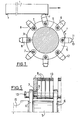
- the deburring machine is represented schematically, under the underside of the slab, by its rotor 4 which comprises a hub 5 on which are fixed landing cheeks 6 regularly spaced in the direction of the longitudinal axis of the hub 5, as well as this appears in Fig. 2.
- the landing cheeks 6 receive a set of articulation pins 7 arranged at equal distance from the axis of the hub 5 and regularly distributed over the periphery of the landing cheeks. In the embodiment shown, eight pins are thus arranged on the landing cheeks, but it is obvious that the number can be varied.
- Hammers 8 are mounted idly on the articulation pins 7. These hammers are in the form of an elongated part, one end of which is pierced with a bore 9 of larger diameter than the diameter of the pins 7, thus achieving a radial clearance between these two elements.
- Fig. 5 showing a detail of the assembly of the hammers 8 between two landing cheeks 6, it can be seen that a group of hammers 8 is mounted on a common spindle 7 passing through all the landing cheeks parallel to a generator of the hub 5.
- all the hammers 8 of each group are identical, but it is possible, according to a variant, to provide for each hammer adjacent to a landing cheek, a part projecting above the landing cheek, so that the set of heads 10 of the hammers covers a complete generator along the length of the machine.
- the heads 10 of the hammers have a dovetail shape so as to have two symmetrical edges 11 and 12 which can be used in one direction of rotation of the shaft or in the other.
- the pins 7 passing through all of the landing cheeks are retained on either side of the end landing cheeks by nuts 13 or by other devices.
- the self-retracting hammers are driven by the hub 5 and under the effect of centrifugal force assume a radial position furthest from the axis of the hub 5.
- the position of the axis of the hub 5 relative to the underside of the slab is adjusted so that during rotation, the envelope of the edges 11, 12 of the heads 9 is substantially tangent to the bottom surface of the slab and intersects the burr.
- the impact of one of the edges 11 or 12 of the head 10 of the hammer on the burr provides the energy necessary to tear off the latter.
- the hammer 8 retracts angularly as indicated, if its energy was not enough to tear off the burr during a first pass, and the next hammer comes to strike the rest of the burr until total elimination of the latter.
- the speed of rotation of the hub 5 is adjusted in order to obtain total elimination of the burr by successive impacts of the hammers on the latter.
- the number of articulation pins 7 supporting the hammers is determined by the speed of rotation of the shaft, the speed of movement of the slab and the number of impacts on the burr necessary to ensure its tearing during its passage through- top of the deburring machine.
- each group of hammers gradually attacks the burr and the energy required upon impact with the latter is much lower, thus reducing the total shock borne by the articulation pins.
- the hammers are in the form of a relatively narrow elongated mass in order to reduce the impact energy which they individually undergo and which is passed on to spindle 7.
- the rotor 4 shown in FIG. 2 in position under a slab 1 is mounted horizontally in a frame consisting of two vertical columns 21, 22 resting on beams 23, 24 themselves supporting the adjacent rollers 31, 32 for discharging the slabs.
- the identical columns 21, 22 consist of two uprights 33, 34 connected at their top by a marquee 35 and delimiting between them a window 36 in which slides a chock 37 carrying the bearing receiving the pin 38 of the rotor 4.
- This chock 37 is integral in translation with the movable rod 39 of a jack 40 mounted on the marquee 35 which allows movement in a vertical direction of the rotor 4.
- This marquee 35 is further provided with two adjustable screw stops 41, 42 which make it possible to adjust the distance separating the axis of the rotor from the underside of the slab.
- the chock 37 is made integral in translation with the rod 39 of the jack by a ball joint 43 fixed to the rod of the jack and whose ball joint is housed in a yoke 44 provided with two orifices 45, 46 in coincidence, in which is threaded an axis 47 passing through the ball joint of the nozzle 43 and fixed to the yoke 44 by a plate stop 48. In the rotor rest position, the chock 37 comes to rest on the stop 49.
- the rotor 4 is rotated by an electric motor 50 which is coupled to it by means of a cardan transmission 51 protected by a gutter 52.
- the axis of the rotor can be inclined at an angleo ⁇ relative to normal to the longitudinal axis of the slab removal table in order to reduce the torque necessary for the elimination of these burrs which are attacked gradually by the same generator of rotor hammers as the slab advances 1.
- the starting of the motor 50, the lifting of the rotor 4 by vertical sliding of the chocks 37 in the frame under the action of the jacks 40, as well as the descent and the reversal of the direction of rotation of the motor 50 are controlled by a device 70 connected to sensors such as infrared cells C1, C2 and C3 placed as shown in FIGS. 3 and 4, laterally and above the slabs whose passage they detect.
- the cells C1 and C2 are placed upstream of the rotor 4 and the cell C3 is placed immediately downstream, although other arrangements can be envisaged to refine the accuracy of the position detection of the slab.
- a logic circuit controls, depending on the presence or absence of the slab opposite each of the sensors C1, C2 and C3, the phases of the deburring operation which takes place as follows: before the arrival of the slab head, moving from right to left as indicated by the arrow A, the rotor is rotated in an anticlockwise direction seen in FIG. 3, during the passage of the slab to the right of the cell Cl, then the rotor is mounted in a tangential position to the underside of the slab when the head of the latter arrives at the right of cell C2. When the slab head arrives at cell C3, the rotor is lowered and stopped.
- the rotor After detection of the passage of the slab foot in C1, the rotor is rotated in opposite direction relative to the slab head, then the detection by C2 of the passage of the slab foot causes the rotor to rise to the deburring position and the detection of the passage of the slab foot at C3 determines the end of the deburring cycle of a slab.
- burrs torn off by the hammers are recovered by a protective cover 60 also including the adjacent rollers 31 and 32 and fall into a hopper 61 then onto a conveyor belt 62 whose longitudinal axis coincides in projection with that of the rotor 4. Burrs are then discharged through a weir 63 onto another conveyor belt 64 and finally stored in a bucket 65 for evacuation.
- the direction of travel of the burrs is illustrated by the arrows B.
Landscapes
- Engineering & Computer Science (AREA)
- Mechanical Engineering (AREA)
- Milling, Broaching, Filing, Reaming, And Others (AREA)
- Milling Processes (AREA)
- Crushing And Pulverization Processes (AREA)
- Percussive Tools And Related Accessories (AREA)
- Grinding And Polishing Of Tertiary Curved Surfaces And Surfaces With Complex Shapes (AREA)
- Mechanical Treatment Of Semiconductor (AREA)
- Processing Of Stones Or Stones Resemblance Materials (AREA)
- Processing And Handling Of Plastics And Other Materials For Molding In General (AREA)
- Punching Or Piercing (AREA)
- Finish Polishing, Edge Sharpening, And Grinding By Specific Grinding Devices (AREA)
- Continuous Casting (AREA)
Priority Applications (1)
| Application Number | Priority Date | Filing Date | Title |
|---|---|---|---|
| AT86400753T ATE36125T1 (de) | 1985-04-12 | 1986-04-08 | Entgratungsmaschine fuer straenge. |
Applications Claiming Priority (2)
| Application Number | Priority Date | Filing Date | Title |
|---|---|---|---|
| FR8505553A FR2580203B1 (fr) | 1985-04-12 | 1985-04-12 | Machine d'ebavurage de brames |
| FR8505553 | 1985-04-12 |
Publications (2)
| Publication Number | Publication Date |
|---|---|
| EP0198768A1 true EP0198768A1 (de) | 1986-10-22 |
| EP0198768B1 EP0198768B1 (de) | 1988-08-03 |
Family
ID=9318185
Family Applications (1)
| Application Number | Title | Priority Date | Filing Date |
|---|---|---|---|
| EP86400753A Expired EP0198768B1 (de) | 1985-04-12 | 1986-04-08 | Entgratungsmaschine für Stränge |
Country Status (12)
| Country | Link |
|---|---|
| US (1) | US4672726A (de) |
| EP (1) | EP0198768B1 (de) |
| JP (1) | JPS61236412A (de) |
| KR (1) | KR940010893B1 (de) |
| CN (1) | CN1004474B (de) |
| AT (1) | ATE36125T1 (de) |
| BR (1) | BR8601655A (de) |
| CA (1) | CA1251626A (de) |
| DE (1) | DE3660443D1 (de) |
| ES (1) | ES8704100A1 (de) |
| FR (1) | FR2580203B1 (de) |
| IN (1) | IN167215B (de) |
Cited By (5)
| Publication number | Priority date | Publication date | Assignee | Title |
|---|---|---|---|---|
| EP0446256A4 (en) * | 1988-12-02 | 1991-09-25 | The Broken Hill Proprietary Company Limited | A deburrer assembly for the removal of burrs and other defects from the surface of castings |
| EP0654313A1 (de) * | 1993-11-18 | 1995-05-24 | Sollac | Vorrichtung zum Entgraten von stranggegossenen Bremmen und Rotor für solche Vorrichtung |
| EP0671230A1 (de) * | 1994-03-11 | 1995-09-13 | HORST K. LOTZ Feuerschutzbaustoffe | Stahlstranggiessanlage mit angeschlossenem oder nachgeschaltetem Entbartungssystem für Sauerstoffschneidbärte und Schneidperlen an Strängen, Brammen und Blöcken |
| US6219894B1 (en) | 1998-08-19 | 2001-04-24 | Gega Corporation | Deburrer for continuous steel casting installation |
| US6277322B1 (en) | 1999-03-08 | 2001-08-21 | Gega Corporation | Deburring apparatus |
Families Citing this family (29)
| Publication number | Priority date | Publication date | Assignee | Title |
|---|---|---|---|---|
| DE9014962U1 (de) * | 1990-10-30 | 1991-01-10 | Plakoma Planungen und Konstruktionen von maschinellen Einrichtungen GmbH, 6638 Dillingen | Vorrichtung zum Entfernen von Brennbärten an Brennschneidkanten von Metallteilen |
| JPH04270044A (ja) * | 1991-02-25 | 1992-09-25 | Nkk Corp | 鋳片のバリ除去方法 |
| DE4321345C1 (de) * | 1993-06-26 | 1994-08-18 | Handtmann A Punkt Automation | Putzwerkzeug |
| DE59407135D1 (de) * | 1994-03-16 | 1998-11-26 | Lotz H K Feuerschutzbaustoffe | Stahlstranggiessanlage mit im Einrichtung zum Entbarten von Strängen oder Strangstücken |
| DE59605139D1 (de) * | 1996-10-26 | 2000-06-08 | Lotz H K Feuerschutzbaustoffe | Entbartereinrichtung und -werkzeuge für Stahlstranggiessanlagen |
| EP0947264A3 (de) | 1997-04-21 | 1999-10-20 | AUTE Gesellschaft für autogene Technik mbH | Stahlstranggiessanlage mit Entbarter |
| EP0947263A1 (de) * | 1998-02-06 | 1999-10-06 | Aute AG Gesellschaft für autogene Technik | Entbarter für durch thermochemisches Trennen unterteilte Knüppel und Brammen, insbesondere in und nach Stahlstranggiessanlagen |
| DE50015372D1 (de) * | 2000-07-15 | 2008-11-06 | Aute Autogene Tech | Mechanischer Schälentbarter zum Entfernen von Sauerstoffschneidbärten und -schneidperlen nach dem thermochemischen Querteilen oder Längsteilen von stählernen Werkstücken wie Brammen, Blöcken und Knüppeln |
| US6473952B1 (en) | 2000-10-13 | 2002-11-05 | Charles J. Gedrich | Deburrer device |
| US7003997B2 (en) * | 2001-04-11 | 2006-02-28 | Solidimension Ltd. | Method and apparatus to reduce deformation in sheets cut by cutting tool |
| US20040093707A1 (en) * | 2002-11-19 | 2004-05-20 | Pro-Line Automation Systems Ltd. | Combination of support post assembly and tools supported thereby |
| JP5071119B2 (ja) * | 2008-01-23 | 2012-11-14 | 住友金属工業株式会社 | 連続鋳造鋳片のバリ除去方法 |
| US20100218354A1 (en) * | 2009-03-02 | 2010-09-02 | Fremstad Gregory E | Method and apparatus for removing slag and burrs from a metal surface |
| AT507912B1 (de) * | 2009-03-11 | 2013-04-15 | Stommel & Voos Marking Technologies Gmbh | Vorrichtung zum entgraten metallischer blöcke |
| ES2400059T3 (es) * | 2010-02-10 | 2013-04-05 | Gega Gmbh | Sistema de remoción de rebabas para la remoción mecánica de rebabas de corte en una pieza de trabajo de fundición contínua |
| AT510876A1 (de) | 2011-01-04 | 2012-07-15 | Numtec Interstahl Gmbh | Vorrichtung für das entgraten von metallteilen |
| CN103619509A (zh) * | 2012-06-21 | 2014-03-05 | GeGa洛茨有限公司 | 用于除去板坯上的毛刺的毛刺去除装置 |
| CN103286288A (zh) * | 2013-06-20 | 2013-09-11 | 北京中远通科技有限公司 | 一种连铸去毛刺机旋转的控制方法 |
| JP6264784B2 (ja) * | 2013-08-30 | 2018-01-24 | 株式会社ジェイテクト | 切削工具 |
| CN103978341A (zh) * | 2014-05-30 | 2014-08-13 | 济钢集团有限公司 | 一种分段式去毛刺辊 |
| CN104368980B (zh) * | 2014-11-27 | 2017-03-01 | 丹阳市腾辉液压机械有限公司 | 一种液压阀底板连续成型加工系列 |
| CN104368981A (zh) * | 2014-11-27 | 2015-02-25 | 丹阳市腾辉液压机械有限公司 | 一种液压阀底板连续加工成型系列的加热除毛刺装置 |
| CN104668496B (zh) * | 2015-02-15 | 2017-05-17 | 江苏联峰能源装备有限公司 | 一种连铸坯料端面割瘤自动精整线 |
| CN105127388B (zh) * | 2015-09-10 | 2017-10-03 | 江苏环信机械工程有限公司 | 去割瘤装置 |
| CN105562830B (zh) * | 2015-12-17 | 2017-08-22 | 马鞍山钢铁股份有限公司 | 毛刺切削设备 |
| CN106002524B (zh) * | 2016-08-08 | 2018-05-18 | 浙江坤博机械制造有限公司 | 一种毛刺检查去除装置 |
| CN111375843B (zh) * | 2020-05-07 | 2023-10-03 | 山东钢铁股份有限公司 | 一种飞铲式钢坯切割端面残渣清除装置 |
| CN114850141B (zh) * | 2022-07-06 | 2022-09-20 | 山东乾通重工科技有限公司 | 一种钢结构焊渣自动清洁设备 |
| CN118744126A (zh) * | 2024-06-25 | 2024-10-08 | 邯郸钢铁集团有限责任公司 | 一种减少机清铸坯表面高棱及漏清的方法 |
Citations (1)
| Publication number | Priority date | Publication date | Assignee | Title |
|---|---|---|---|---|
| US1328034A (en) * | 1918-12-30 | 1920-01-13 | American Brass Co | Means for scalping or overhauling metal |
Family Cites Families (15)
| Publication number | Priority date | Publication date | Assignee | Title |
|---|---|---|---|---|
| US1984762A (en) * | 1933-05-24 | 1934-12-18 | Samuel S Roberts | Descaler |
| US2256559A (en) * | 1939-07-22 | 1941-09-23 | Gen Motors Corp | Flash remover |
| US2664281A (en) * | 1949-08-27 | 1953-12-29 | Tennant Co G H | Machine for cutting, cleaning, grooving, and treating surfaces |
| US2746127A (en) * | 1953-03-06 | 1956-05-22 | Descaling Equipment Co Inc | Descaling wheel |
| US3198081A (en) * | 1963-03-19 | 1965-08-03 | Taylor Wintield Corp | Apparatus for trimming flash from strip |
| SU512001A2 (ru) * | 1973-11-29 | 1976-04-30 | Институт черной металлургии | Устройство дл сн ти грата |
| JPS5939023B2 (ja) * | 1978-11-29 | 1984-09-20 | ワイケ−トレ−デイング株式会社 | 衝打型切削機のカツタ− |
| JPS608882Y2 (ja) * | 1979-10-09 | 1985-03-30 | 日本鋼管株式会社 | 連鋳スラブの切断バリ除去装置 |
| JPS61979Y2 (de) * | 1980-06-16 | 1986-01-14 | ||
| US4372020A (en) * | 1981-05-26 | 1983-02-08 | Anderson Engineers, Inc. | Slag removal apparatus |
| US4443143A (en) * | 1982-03-08 | 1984-04-17 | Kabushiki Kaisha Kobe Seiko Sho | Billet scalper and drive mechanism therefor |
| FR2524355A1 (fr) * | 1982-04-06 | 1983-10-07 | Fives Cail Babcock | Appareil pour enlever les bavures sur un produit de coulee continue |
| US4522540A (en) * | 1982-04-09 | 1985-06-11 | Nippon Kokan Kabushiki Kaisha | Method and apparatus for removing cutting burr sticking to lower surface of slab |
| JPH113389A (ja) * | 1997-06-11 | 1999-01-06 | Yozan:Kk | 重み付加算回路 |
| JPH112593A (ja) * | 1997-06-13 | 1999-01-06 | Kdk Corp | 余剰液除去装置 |
-
1985
- 1985-04-12 FR FR8505553A patent/FR2580203B1/fr not_active Expired
-
1986
- 1986-04-02 IN IN239/MAS/86A patent/IN167215B/en unknown
- 1986-04-07 KR KR1019860002603A patent/KR940010893B1/ko not_active Expired - Lifetime
- 1986-04-08 AT AT86400753T patent/ATE36125T1/de not_active IP Right Cessation
- 1986-04-08 DE DE8686400753T patent/DE3660443D1/de not_active Expired
- 1986-04-08 EP EP86400753A patent/EP0198768B1/de not_active Expired
- 1986-04-08 US US06/849,466 patent/US4672726A/en not_active Expired - Lifetime
- 1986-04-11 JP JP61084006A patent/JPS61236412A/ja active Granted
- 1986-04-11 CA CA000506450A patent/CA1251626A/en not_active Expired
- 1986-04-11 BR BR8601655A patent/BR8601655A/pt not_active IP Right Cessation
- 1986-04-11 CN CN86102455.9A patent/CN1004474B/zh not_active Expired
- 1986-04-11 ES ES554220A patent/ES8704100A1/es not_active Expired
Patent Citations (1)
| Publication number | Priority date | Publication date | Assignee | Title |
|---|---|---|---|---|
| US1328034A (en) * | 1918-12-30 | 1920-01-13 | American Brass Co | Means for scalping or overhauling metal |
Non-Patent Citations (1)
| Title |
|---|
| REVUE DE METALLURGIE-CIT, juin 1983, page 490, Paris, FR; "Information des machines de coulée" * |
Cited By (7)
| Publication number | Priority date | Publication date | Assignee | Title |
|---|---|---|---|---|
| EP0446256A4 (en) * | 1988-12-02 | 1991-09-25 | The Broken Hill Proprietary Company Limited | A deburrer assembly for the removal of burrs and other defects from the surface of castings |
| EP0654313A1 (de) * | 1993-11-18 | 1995-05-24 | Sollac | Vorrichtung zum Entgraten von stranggegossenen Bremmen und Rotor für solche Vorrichtung |
| FR2712518A1 (fr) * | 1993-11-18 | 1995-05-24 | Lorraine Laminage | Machine d'ébavurage de brames issues d'une installation de coulée continue et rotor utilisé dans ce type de machine d'ébavurage. |
| US5520241A (en) * | 1993-11-18 | 1996-05-28 | Sollac | Machine for removing burrs from slabs issuing from a continuous casting installation and rotor employed in this type of burr-removing machine |
| EP0671230A1 (de) * | 1994-03-11 | 1995-09-13 | HORST K. LOTZ Feuerschutzbaustoffe | Stahlstranggiessanlage mit angeschlossenem oder nachgeschaltetem Entbartungssystem für Sauerstoffschneidbärte und Schneidperlen an Strängen, Brammen und Blöcken |
| US6219894B1 (en) | 1998-08-19 | 2001-04-24 | Gega Corporation | Deburrer for continuous steel casting installation |
| US6277322B1 (en) | 1999-03-08 | 2001-08-21 | Gega Corporation | Deburring apparatus |
Also Published As
| Publication number | Publication date |
|---|---|
| ES8704100A1 (es) | 1987-04-01 |
| CA1251626A (en) | 1989-03-28 |
| EP0198768B1 (de) | 1988-08-03 |
| JPH0545362B2 (de) | 1993-07-09 |
| ES554220A0 (es) | 1987-04-01 |
| US4672726A (en) | 1987-06-16 |
| CN86102455A (zh) | 1986-10-08 |
| FR2580203A1 (fr) | 1986-10-17 |
| ATE36125T1 (de) | 1988-08-15 |
| JPS61236412A (ja) | 1986-10-21 |
| FR2580203B1 (fr) | 1987-08-28 |
| DE3660443D1 (en) | 1988-09-08 |
| KR940010893B1 (ko) | 1994-11-19 |
| KR860007986A (ko) | 1986-11-10 |
| CN1004474B (zh) | 1989-06-14 |
| IN167215B (de) | 1990-09-22 |
| BR8601655A (pt) | 1986-12-16 |
Similar Documents
| Publication | Publication Date | Title |
|---|---|---|
| EP0198768B1 (de) | Entgratungsmaschine für Stränge | |
| EP0654313B1 (de) | Vorrichtung zum Entgraten von stranggegossenen Bremmen und Rotor für solche Vorrichtung | |
| EP0388318A1 (de) | Verfahren und Vorrichtung zum Bilden eines neuen Stapels nach dem Abnehmen von einem fertigen Stapel, in einer, insbesondere einem Printer zugeordneten, Stapelbildungsmaschine | |
| EP2964412B1 (de) | Verfahren und anlage zur umwandlung eines flüssigen metalls in ein festes metall | |
| EP3814017B1 (de) | Fensterglassfragmentierungsvorrichtung | |
| EP0276848A2 (de) | Rotierender Brecher mit geschützten Schleuderradschaufeln | |
| FR2537040A1 (fr) | Procede de fabrication de pieces de bois travaillees sur toutes les faces, et dispositif pour la mise en oeuvre de ce procede | |
| FR2595040A1 (fr) | Installation pour parer des endives ou des legumes similaires | |
| EP3222367B1 (de) | Verfahren und vorrichtung zur behandlung von platten | |
| EP0115759B1 (de) | Verfahren und Vorrichtung zum Entfernen des abgesägten Endes eines rohrförmigen Stückes, z.B. eines gusseisernen Rohres | |
| EP1120183B1 (de) | Zwischenplatte zum Einsetzen in einem Schneidschlitz | |
| EP0028220A1 (de) | Transportvorrichtung für mittellange abstände. | |
| EP0894034A1 (de) | Vorrichtung zum beseitigen von brennbärten | |
| FR2811605A1 (fr) | Dispositif pour la separation de produits scies, en sortie d'une deligneuse | |
| EP0104292B1 (de) | Verfahren und Vorrichtung zum Abgeben von thermo-schrumpfbaren Kappen, die auf sich bewegende Behälter fallen | |
| JPH04270043A (ja) | ビームブランク鋳片のトーチダレ除去装置 | |
| FR2531894A1 (fr) | Appareil et procede de nettoyage et d'avance de pieces | |
| EP1277660A1 (de) | Vorrichtung zum Öffnen von Schachteln | |
| FR2512361A1 (fr) | Convoyeur pour l'evacuation de toles cisaillees a l'arriere d'une cisaille guillotine | |
| CA2250762A1 (fr) | Dispositif d'ebavurage de brames | |
| FR2467054A1 (fr) | Installation pour l'ejection laterale de tubes etires en longueur | |
| FR2610218A1 (fr) | Concasseur rotatif a projection | |
| FR2667484A1 (fr) | Procede et machine pour eteter et equeuter des plantes a bulbe allonge, et notamment des echalotes. | |
| BE641695A (de) | ||
| BE891168A (fr) | Appareil pour enlever l'appendice de coupe par fusion sur une brame d'acier obtenue par coulee continue |
Legal Events
| Date | Code | Title | Description |
|---|---|---|---|
| PUAI | Public reference made under article 153(3) epc to a published international application that has entered the european phase |
Free format text: ORIGINAL CODE: 0009012 |
|
| AK | Designated contracting states |
Kind code of ref document: A1 Designated state(s): AT BE CH DE FR GB IT LI LU NL SE |
|
| 17P | Request for examination filed |
Effective date: 19860903 |
|
| 17Q | First examination report despatched |
Effective date: 19870902 |
|
| GRAA | (expected) grant |
Free format text: ORIGINAL CODE: 0009210 |
|
| AK | Designated contracting states |
Kind code of ref document: B1 Designated state(s): AT BE CH DE FR GB IT LI LU NL SE |
|
| REF | Corresponds to: |
Ref document number: 36125 Country of ref document: AT Date of ref document: 19880815 Kind code of ref document: T |
|
| ITF | It: translation for a ep patent filed | ||
| REF | Corresponds to: |
Ref document number: 3660443 Country of ref document: DE Date of ref document: 19880908 |
|
| GBT | Gb: translation of ep patent filed (gb section 77(6)(a)/1977) | ||
| PLBE | No opposition filed within time limit |
Free format text: ORIGINAL CODE: 0009261 |
|
| STAA | Information on the status of an ep patent application or granted ep patent |
Free format text: STATUS: NO OPPOSITION FILED WITHIN TIME LIMIT |
|
| 26N | No opposition filed | ||
| ITTA | It: last paid annual fee | ||
| EPTA | Lu: last paid annual fee | ||
| EAL | Se: european patent in force in sweden |
Ref document number: 86400753.9 |
|
| REG | Reference to a national code |
Ref country code: GB Ref legal event code: IF02 |
|
| PGFP | Annual fee paid to national office [announced via postgrant information from national office to epo] |
Ref country code: CH Payment date: 20050315 Year of fee payment: 20 |
|
| PGFP | Annual fee paid to national office [announced via postgrant information from national office to epo] |
Ref country code: AT Payment date: 20050317 Year of fee payment: 20 |
|
| PGFP | Annual fee paid to national office [announced via postgrant information from national office to epo] |
Ref country code: SE Payment date: 20050318 Year of fee payment: 20 Ref country code: LU Payment date: 20050318 Year of fee payment: 20 |
|
| PGFP | Annual fee paid to national office [announced via postgrant information from national office to epo] |
Ref country code: NL Payment date: 20050322 Year of fee payment: 20 |
|
| PGFP | Annual fee paid to national office [announced via postgrant information from national office to epo] |
Ref country code: GB Payment date: 20050329 Year of fee payment: 20 |
|
| PGFP | Annual fee paid to national office [announced via postgrant information from national office to epo] |
Ref country code: DE Payment date: 20050408 Year of fee payment: 20 |
|
| PGFP | Annual fee paid to national office [announced via postgrant information from national office to epo] |
Ref country code: IT Payment date: 20050418 Year of fee payment: 20 Ref country code: FR Payment date: 20050418 Year of fee payment: 20 |
|
| PGFP | Annual fee paid to national office [announced via postgrant information from national office to epo] |
Ref country code: BE Payment date: 20050429 Year of fee payment: 20 |
|
| REG | Reference to a national code |
Ref country code: GB Ref legal event code: PE20 |
|
| PG25 | Lapsed in a contracting state [announced via postgrant information from national office to epo] |
Ref country code: GB Free format text: LAPSE BECAUSE OF EXPIRATION OF PROTECTION Effective date: 20060407 |
|
| PG25 | Lapsed in a contracting state [announced via postgrant information from national office to epo] |
Ref country code: NL Free format text: LAPSE BECAUSE OF EXPIRATION OF PROTECTION Effective date: 20060408 |
|
| NLV7 | Nl: ceased due to reaching the maximum lifetime of a patent |
Effective date: 20060408 |
|
| EUG | Se: european patent has lapsed | ||
| BE20 | Be: patent expired |
Owner name: *USINOR ACIERS Effective date: 20060408 |