EP0201469B1 - Dispositif de prise par succion pour usage industriel - Google Patents
Dispositif de prise par succion pour usage industriel Download PDFInfo
- Publication number
- EP0201469B1 EP0201469B1 EP86850131A EP86850131A EP0201469B1 EP 0201469 B1 EP0201469 B1 EP 0201469B1 EP 86850131 A EP86850131 A EP 86850131A EP 86850131 A EP86850131 A EP 86850131A EP 0201469 B1 EP0201469 B1 EP 0201469B1
- Authority
- EP
- European Patent Office
- Prior art keywords
- holder
- vacuum
- sealing
- backpiece
- maintaining element
- Prior art date
- Legal status (The legal status is an assumption and is not a legal conclusion. Google has not performed a legal analysis and makes no representation as to the accuracy of the status listed.)
- Expired - Lifetime
Links
Images
Classifications
-
- B—PERFORMING OPERATIONS; TRANSPORTING
- B66—HOISTING; LIFTING; HAULING
- B66C—CRANES; LOAD-ENGAGING ELEMENTS OR DEVICES FOR CRANES, CAPSTANS, WINCHES, OR TACKLES
- B66C1/00—Load-engaging elements or devices attached to lifting or lowering gear of cranes or adapted for connection therewith for transmitting lifting forces to articles or groups of articles
- B66C1/02—Load-engaging elements or devices attached to lifting or lowering gear of cranes or adapted for connection therewith for transmitting lifting forces to articles or groups of articles by suction means
- B66C1/0212—Circular shape
-
- B—PERFORMING OPERATIONS; TRANSPORTING
- B65—CONVEYING; PACKING; STORING; HANDLING THIN OR FILAMENTARY MATERIAL
- B65G—TRANSPORT OR STORAGE DEVICES, e.g. CONVEYORS FOR LOADING OR TIPPING, SHOP CONVEYOR SYSTEMS OR PNEUMATIC TUBE CONVEYORS
- B65G47/00—Article or material-handling devices associated with conveyors; Methods employing such devices
- B65G47/74—Feeding, transfer, or discharging devices of particular kinds or types
- B65G47/90—Devices for picking-up and depositing articles or materials
- B65G47/91—Devices for picking-up and depositing articles or materials incorporating pneumatic, e.g. suction, grippers
-
- B—PERFORMING OPERATIONS; TRANSPORTING
- B66—HOISTING; LIFTING; HAULING
- B66C—CRANES; LOAD-ENGAGING ELEMENTS OR DEVICES FOR CRANES, CAPSTANS, WINCHES, OR TACKLES
- B66C1/00—Load-engaging elements or devices attached to lifting or lowering gear of cranes or adapted for connection therewith for transmitting lifting forces to articles or groups of articles
- B66C1/02—Load-engaging elements or devices attached to lifting or lowering gear of cranes or adapted for connection therewith for transmitting lifting forces to articles or groups of articles by suction means
- B66C1/0231—Special lip configurations
Definitions
- the invention relates to a holder fixed by vacuum for industrial use, of the kind described in the preamble of claim 1 (FR-A 2 249 826).
- suction cups which are rigidly connected to the set-up for carrying out the respective function.
- the suction cups are attached by suction to suitable, preferentially flat or slightly bent, surfaces of the workpiece to be held attached, displaced laterally, or lifted, by means of the negative pressure in the suction cups and in the evacuation system connected to them, and they are effected to loose their hold in that the negative pressure is removed by valve-controlled pressurizing.
- the suction cups presently used for this purpose are of a very simple design such as the arrangement described in FR-A 2 511 921. It consists of a rigid shaft with a centrally located bore extending through its entire length provided with a flexible circumferential sealing element and with a valve located at the front end of the bore which is activated after the sealing lip has made contact with the object to be kept attached.
- the shaft widens conically at its front end and, in attached position, abuts abuts against the object kept fixed.
- the flexible sealing element is not peripherally supported against the shaft when the arragement is in active state.
- FR-A 249 826 Another known arrangement is the suction holder of FR-A 249 826.
- This holder has been specifically designed to allow attachment to objects at high temperatures. It differs, i.a. from the suction cup according to FR-A 2 511 921 in that it has no valve which automatically opens when the holder is becoming attached to an object to be kept fixed.
- the holder is provided with peripherally arranged support means securing attachment of the flexible and radially segmented metal sealing element in a working state.
- valve means in a holder or suction cup preventing air to be sucked into it while in an idle position is a technical drawback in terms of reliability of attachment. It can be overcome by over-dimensioning the means for providing negative pressure but this will increase cost and create excessive noise and, thereby, occupational health problems. It can also be overcome, at extra cost, by arranging actively controlled valve means in the system providing negative pressure or by using at least two independent negative pressure systems.
- suction cups or holders with a circumferential flexible sealing lip of the specific design disclosed in FR-A 2 511 921 not incorporating support means makes them unstable, especially under heavy load.
- suction holder of FR-A 249 826 is provided with such support means, it lacks the valve means of FR-A 2 511 921, and vice versa.
- the object of the invention is a holder fixed by vacuum for industrial use which is self-sealing in an idle state and which allows an object to be kept firmly attached at relatively low negative pressures.
- the object of the invention has now surprisingly been achieved by the design of a holder which comprises these properties and does so without the use of advanced controlling and regulating technology, . and without the need for over-dimensioning of suction pumps.
- the object of the invention has been achieved in form of a holder fixed by vacuum, connected to a vacuum pump or to a vacuum reservoir and which can be permanently or temporarily attached to a lifting arrangement or to an arrangement for lateral displacement or just for keeping fixed, and abutting with its front side against the object to be displaced, lifted, or kept fixed, in the following called workpiece, and which comprises a rigid back- piece and at least partially flexible sealing means, and an essentially rigid central distance-maintaining element, which sealing means comprise a sealing ring ending in a sealing lip, which when fixed at the workpiece abuts against a preferentially flat or moderately curved surface workpiece, so that a volume in communication with the vacuum source and defined by said surface and sealing means is delimited, whereby said distance-maintaining element and said sealing lip are movably arranged relatively to each other under the influence of a resilient force operating through spring means, which strives to separate the distance-maintaining element from a plane defined by the sealing lip, from a working
- a self-sealing holder according to the invention dispenses with the need to use multiple separate systems or over-dimensioned vacuum pumps in order to attain acceptable safety. Holders according to the invention will also operate considerably more silently than systems provided with suction cups according to known technology.
- a minor force is needed for activation. This force is produced by moving the holder with part of the lifting arrangement towards the surface of the workpiece or by adapting its weight or its weight in combination with the part of the lifting arrangement rigidly connected to it, so that activation is achieved by its own weight when it rests against the surface of the workpiece.
- the holder is preferentially attached to flat or moderately curved surfaces.
- the holder is preferentially attached to flat or moderately curved surfaces.
- the sealing ring which ends in a sealing lip in relation to the distance-maintaining element, as well as by curved design of the surface of the distance-maintaining element facing at surface of the object, even objects lacking suitable flat or moderately curved surfaces can be held attached.
- the surface or the distance-maintaining element can be made of or be coated with an elastic resilient material.
- Conduction of vacuum to the holder according to the invention is achieved by means of a flexible vacuum hose, but may of course be done in metal tubes or in channels in the part of the arrangement for lifting or keeping attached which is rigidly connected to the holder.
- the holder may be rigidly or removably connected to an arrangement for lifting, for lateral displacement, for keeping attached only, or to an arrangement combining two or all of these functions.
- the attachment is advantageously carried out in an active way by externally controlled force impact, while disengagement is obtained by putting the holder under pressure by a pressurized air pulse generated in an arrangement of known type, which is arranged between the holder and the vacuum source, and which simultaneously with the pressure pulse temporarily closes the part of the vacuum system facing the vacuum source. If the frequency of repeated working steps does not necessitate such a disengagement effected by a pressure pulse, the arrangement of a simple aeration valve between the holder and the vacuum system suffices, preferentially in combination with an arrangement for temporary closing the part of the conduction system facing the vacuum source.
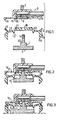
- Figure 1 shows an exploded view of a holder fixed by vacuum consisting of three components.
- Figure 2 shows a cross-sectional view of a holder in an idle position
- Figure 3 shows a cross-sectional view of a holder in an active position, i.e. with the holder attached to the object, which is to be lifted, displaced laterally, or only is to be kept fixed.
- Distance-maintaining element 1 has a surface 4 adapted to the workpiece, in the present case a flat surface. Surface 4 is covered by a thin layer of rubber, not shown in the Figures.
- the outer form of the distance-maintaining element 1 in addition to that is determined by the described cooperation with the other components of the holder, especially with lip 14.
- the distanc-maintaining element 1 has in its part facing backpiece 3 a stem-like part, at the end of which an external thread 5 is arranged fitting into an internal thread 6 located in backpiece 3, whereby element 1 can be secured at the backpiece by screwing on.
- the depth of screw both in backpiece 3 and on stem 5 is adapted to give the correct distance between surface 4 and other parts of the holder, especially sealing lip 13 on ring 9.
- the stem part 5 penetrates a hole 18 in an intermediate element 2, which incorporates i.a. sealing ring 9.
- Backpiece 3 is provided with attachment means 7 in order to be attached to the lifting, transport or attachment arrangement.
- the attachment of hose 8 to backpiece 3 leads to a volume in the upper part of the backpiece, form where there are arranged a number of holes 20 around the part of attachment of the central distance-maintaining element, which holes provide communication of said volume to the surface of backpiece 3 facing intermediate element 2.
- part 1 and 2 are rotationally symmetric. This simplifies manufacture but is not absolutely necessary.
- Part 2 which is made of rubber or some similar elastic material has a relatively rigid outer circular portion 9 with a circumferentially arranged sealing lip 13 which, in an active position, is sealing against the workpiece.
- a relatively rigid outer circular portion 9 with a circumferentially arranged sealing lip 13 which, in an active position, is sealing against the workpiece.
- a second room V 2 defined by the peripheral portion of intermediate element 2, by the portion of the workpiece delimited by ring 9 with sealing lip 13, and by the peripheral part of central distance-maintaining element 1, communicates with the vaccum source via the first volume V i mentioned above. Because by holes 12 are provided in the peripheral part of intermediate element 2, a third volume V 3 will become provided with vacuum, which volum is located between the peripheral portions of intermediate element 2 and backpiece 3, whereby sealing lips 13 and 16 are sealing between backpiece 3 and the surface of the workpiece. Thereby, the configuration shown in Fig. 3 is obtained. From Fig.
- backpiece 3 and ring 9 are functioning as a coherent entity, although an elastic deformational force affects ring 9 in radial direction from backpiece 3 through flange 17, which deformational force however is negligible in comparison with the pneumatic forces.
- a break force affecting the attachment between the suction cup and the surface of the object held attached will result in a deformation of intermediate element 2, until the abutment of lip 13 ceases and air enters. Thereby the holder falls off and flange 14 resiliently moves back, and the position shown in Fig. 2 with the valve seal once again in effect is obtained.
- the surface 4 of the distance-maintaining element 1 in the position shown in Fig. 2 must be inwardly drawn in relation to lip 13 on the ring 9.
- the described embodiment has found to function well. For example, at a negative pressure of 0.1 kp/cm 2 , a prototype with a diameter of 30 mm for ring 9 has been shown to be able to lift a workpiece with flat surfaces weighing 300 g.
- the portions of the intermediate element 2 that must be relatively rigid have to be strengthened e.g. by reinforcements.
- the holder is manufactured in large dimensions, it might be advantageous not to make the intermediate element 2 in one single piece, but rather by assembling several parts which are adapted to each other dimension-wise and with respect to material properties.
- connection between distance-maintaining element 1 and backpiece 3 may also be arranged in form of a press-stud connection or in a similar way, provided that the load affecting the holder is small, and when it is desirable to make the distance-maintaining element 1 and the intermediate element 2 easily exchangeable, e.g. in order to facilitate cleaning.
Landscapes
- Engineering & Computer Science (AREA)
- Mechanical Engineering (AREA)
- Manipulator (AREA)
- Load-Engaging Elements For Cranes (AREA)
- Hooks, Suction Cups, And Attachment By Adhesive Means (AREA)
- Jigs For Machine Tools (AREA)
- Chain Conveyers (AREA)
- Laminated Bodies (AREA)
- Polymers With Sulfur, Phosphorus Or Metals In The Main Chain (AREA)
- Inorganic Insulating Materials (AREA)
- Organic Low-Molecular-Weight Compounds And Preparation Thereof (AREA)
Claims (5)
Priority Applications (1)
| Application Number | Priority Date | Filing Date | Title |
|---|---|---|---|
| AT86850131T ATE49183T1 (de) | 1985-04-26 | 1986-04-15 | Vakuumgreifer fuer industriegebrauch. |
Applications Claiming Priority (2)
| Application Number | Priority Date | Filing Date | Title |
|---|---|---|---|
| SE8502049 | 1985-04-26 | ||
| SE8502049A SE8502049D0 (sv) | 1985-04-26 | 1985-04-26 | Vakuumfixerad hallare for industriellt bruk |
Publications (3)
| Publication Number | Publication Date |
|---|---|
| EP0201469A2 EP0201469A2 (fr) | 1986-12-17 |
| EP0201469A3 EP0201469A3 (en) | 1987-05-06 |
| EP0201469B1 true EP0201469B1 (fr) | 1990-01-03 |
Family
ID=20359992
Family Applications (1)
| Application Number | Title | Priority Date | Filing Date |
|---|---|---|---|
| EP86850131A Expired - Lifetime EP0201469B1 (fr) | 1985-04-26 | 1986-04-15 | Dispositif de prise par succion pour usage industriel |
Country Status (11)
| Country | Link |
|---|---|
| US (1) | US4708381A (fr) |
| EP (1) | EP0201469B1 (fr) |
| JP (1) | JPS61248896A (fr) |
| CN (1) | CN1005031B (fr) |
| AT (1) | ATE49183T1 (fr) |
| BR (1) | BR8601856A (fr) |
| DE (1) | DE3667958D1 (fr) |
| ES (1) | ES8702294A1 (fr) |
| FI (1) | FI861400L (fr) |
| SE (1) | SE8502049D0 (fr) |
| SU (1) | SU1479000A3 (fr) |
Families Citing this family (39)
| Publication number | Priority date | Publication date | Assignee | Title |
|---|---|---|---|---|
| DE3714388A1 (de) * | 1987-04-30 | 1988-11-10 | Festo Kg | Saugnapf |
| GB2248435B (en) * | 1990-09-06 | 1994-06-22 | Smc Kk | Suction pad |
| JP2586261Y2 (ja) * | 1990-11-08 | 1998-12-02 | エスエムシー 株式会社 | 吸着用パッド |
| US5087005A (en) * | 1991-02-12 | 1992-02-11 | Holoff Richard S | Twist-cam suction cup assembly |
| WO1993016633A1 (fr) * | 1992-02-20 | 1993-09-02 | Humanteknik Ab | Dispositif permettant de fixer un objet sur une surface par le vide |
| SE503420C2 (sv) * | 1993-11-16 | 1996-06-10 | Humanteknik Ab | Absorbentenhet för användning i en biomedicinsk elektrod |
| US5485988A (en) * | 1994-05-31 | 1996-01-23 | Nobilec; Leslaw | Clamping means for ski, or the like |
| US5664617A (en) * | 1995-03-24 | 1997-09-09 | Columbia Aluminum Corporation | Sow lifter |
| US5704599A (en) * | 1996-01-18 | 1998-01-06 | Slothower; Stephen G. | Vacuum apparatus for aligning and securely positioning components |
| US5950670A (en) * | 1996-12-05 | 1999-09-14 | Rayco Manufacturing Inc. | Vacuum cup safety device |
| DE19958890C1 (de) * | 1999-12-07 | 2001-02-15 | Bsh Bosch Siemens Hausgeraete | Sicherheitseinrichtung für eine auf einer Fläche beweglichen Vorrichtung |
| US7309089B2 (en) * | 2004-02-04 | 2007-12-18 | Delaware Capital Formation, Inc. | Vacuum cup |
| US7540309B2 (en) * | 2005-07-11 | 2009-06-02 | Delaware Capital Formation, Inc. | Auto-release vacuum device |
| DE102005047809A1 (de) * | 2005-10-05 | 2007-04-12 | Harald Richter | Saugfuß für Geräteträger oder dergleichen |
| DE102006005872B3 (de) * | 2006-02-06 | 2008-01-31 | J. Schmalz Gmbh | Sauggreifer |
| CN101172539B (zh) * | 2006-11-03 | 2011-05-04 | 鸿富锦精密工业(深圳)有限公司 | 吸附拾取装置 |
| US20100117278A1 (en) * | 2008-11-11 | 2010-05-13 | Chang Yu-Chen | Vacuum sucker for workpiece having through holes |
| US20100150743A1 (en) * | 2008-12-12 | 2010-06-17 | Norgren Automotive, Inc. | Single Line Venturi Apparatus |
| NL2002470C2 (nl) | 2009-01-30 | 2010-08-02 | Sijnja Konstruktie B V | Zuignap en inrichting voorzien van zuignappen. |
| US8382174B2 (en) * | 2009-10-08 | 2013-02-26 | University Of Maryland | System, method, and apparatus for suction gripping |
| CN102241014A (zh) * | 2010-05-12 | 2011-11-16 | 鸿富锦精密工业(深圳)有限公司 | 吸嘴及具有该吸嘴的吸取装置 |
| CN104787656A (zh) * | 2014-01-22 | 2015-07-22 | 上海瓦科自动化设备有限公司 | 一种能够减少吸盘更换频率的管吊装置 |
| US9991152B2 (en) * | 2014-03-06 | 2018-06-05 | Cascade Microtech, Inc. | Wafer-handling end effectors with wafer-contacting surfaces and sealing structures |
| KR101469688B1 (ko) | 2014-03-21 | 2014-12-05 | 한국뉴매틱(주) | 진공 시스템용 체크-밸브 어셈블리 |
| CN104029142B (zh) * | 2014-06-16 | 2016-02-10 | 上海交通大学 | 一种管式弹性零件的夹持装置 |
| TWI524012B (zh) * | 2014-07-31 | 2016-03-01 | Gison Machinery Co Ltd | Sucker |
| US9676102B2 (en) * | 2014-10-24 | 2017-06-13 | Gison Machinery Co., Ltd. | Sucker |
| US9623571B2 (en) * | 2014-12-19 | 2017-04-18 | Penn Engineering & Manufacturing Corp. | Pick and place nozzle adaptor |
| US20160214812A1 (en) * | 2015-01-23 | 2016-07-28 | R.A. Pearson Company | End of Arm Tool for Grasping |
| KR102427644B1 (ko) | 2015-11-16 | 2022-08-02 | 삼성전자주식회사 | 광원 모듈, 광원 모듈의 제조방법 및 이를 포함하는 디스플레이 장치 |
| CN107084185A (zh) * | 2017-05-26 | 2017-08-22 | 苏州驱指自动化科技有限公司 | 抓盘 |
| JP7237925B2 (ja) * | 2017-07-31 | 2023-03-13 | ダウ グローバル テクノロジーズ エルエルシー | フィルムの引き裂き分析のためのシステム |
| CN108082590B (zh) * | 2017-12-29 | 2023-07-25 | 内蒙古蒙牛乳业(集团)股份有限公司 | 一种待灌装容器的固定装置及灌装设备 |
| CN108467988A (zh) * | 2018-02-08 | 2018-08-31 | 江西新能源科技职业学院 | 一种组合机械臂 |
| CN108483037B (zh) * | 2018-03-28 | 2019-09-27 | 南京理工大学 | 一种基于颗粒物塑形的真空吸盘 |
| US11884377B2 (en) * | 2018-12-21 | 2024-01-30 | The Boeing Company | High-density robotic system |
| US11584503B2 (en) * | 2018-12-21 | 2023-02-21 | The Boeing Company | High-density robotic system |
| EP3879139B1 (fr) * | 2020-03-12 | 2022-06-08 | Piab Aktiebolag | Ventouse compressible dotée d'un compartiment supplémentaire sous vide, ainsi que lèvre et soufflets associés |
| US12337467B2 (en) | 2022-12-09 | 2025-06-24 | Formfactor, Inc. | Wafer-handling end effectors configured to selectively lift a wafer from an upper surface of the wafer, probe systems that include the wafer-handling end effectors, and methods of utilizing the wafer-handling end effectors |
Family Cites Families (9)
| Publication number | Priority date | Publication date | Assignee | Title |
|---|---|---|---|---|
| US2680994A (en) * | 1951-10-22 | 1954-06-15 | Boeing Co | Suction holding device |
| US3230002A (en) * | 1963-04-22 | 1966-01-18 | Hyster Co | Suction cup construction and apparatus |
| US3602543A (en) * | 1968-12-18 | 1971-08-31 | Munck Int As | Arrangement in suction cup for vacuum lifting |
| US3863969A (en) * | 1973-11-01 | 1975-02-04 | Aluminum Co Of America | Vacuum lifter |
| US4221356A (en) * | 1978-11-09 | 1980-09-09 | Fortune William S | Vacuum operated holding fixture |
| FR2511921A1 (fr) * | 1981-09-01 | 1983-03-04 | Thimon Ets | Procede de prehension d'un objet au moyen d'un dispositif de prehension a ventouse et dispositif pour sa mise en oeuvre |
| SU1016157A1 (ru) * | 1982-02-14 | 1983-05-07 | Ростовский-на-Дону научно-исследовательский институт технологии машиностроения | Захват вакуумный |
| SE454941B (sv) * | 1983-10-28 | 1988-06-13 | Astra Tech Ab | Elektrod, fastsugbar med vacuum, och en elektrodplatta for en elektrod, avsedd for t ex ekg-metningar |
| US4561687A (en) * | 1984-05-30 | 1985-12-31 | Harris Corporation | Vacuum grip device |
-
1985
- 1985-04-26 SE SE8502049A patent/SE8502049D0/xx unknown
-
1986
- 1986-04-01 FI FI861400A patent/FI861400L/fi not_active Application Discontinuation
- 1986-04-04 US US06/849,481 patent/US4708381A/en not_active Expired - Fee Related
- 1986-04-15 DE DE8686850131T patent/DE3667958D1/de not_active Expired - Lifetime
- 1986-04-15 EP EP86850131A patent/EP0201469B1/fr not_active Expired - Lifetime
- 1986-04-15 AT AT86850131T patent/ATE49183T1/de not_active IP Right Cessation
- 1986-04-24 BR BR8601856A patent/BR8601856A/pt not_active IP Right Cessation
- 1986-04-24 ES ES554318A patent/ES8702294A1/es not_active Expired
- 1986-04-25 JP JP61094976A patent/JPS61248896A/ja active Pending
- 1986-04-25 SU SU864027336A patent/SU1479000A3/ru active
- 1986-04-26 CN CN86102911.9A patent/CN1005031B/zh not_active Expired
Also Published As
| Publication number | Publication date |
|---|---|
| US4708381A (en) | 1987-11-24 |
| CN86102911A (zh) | 1986-12-03 |
| DE3667958D1 (de) | 1990-02-08 |
| BR8601856A (pt) | 1986-12-30 |
| EP0201469A2 (fr) | 1986-12-17 |
| FI861400A0 (fi) | 1986-04-01 |
| ATE49183T1 (de) | 1990-01-15 |
| EP0201469A3 (en) | 1987-05-06 |
| SU1479000A3 (ru) | 1989-05-07 |
| JPS61248896A (ja) | 1986-11-06 |
| SE8502049D0 (sv) | 1985-04-26 |
| ES8702294A1 (es) | 1987-01-01 |
| FI861400A7 (fi) | 1986-10-27 |
| ES554318A0 (es) | 1987-01-01 |
| FI861400L (fi) | 1986-10-27 |
| CN1005031B (zh) | 1989-08-23 |
Similar Documents
| Publication | Publication Date | Title |
|---|---|---|
| US4708381A (en) | Holder fixed by vacuum for industrial use | |
| US5263753A (en) | Gripper for a manipulator | |
| EP1088624B1 (fr) | Ventouse avec un arrêt rigide de précision | |
| EP0951944B1 (fr) | Pompe à membrane bombée pour distributeurs de liquide du type à gàchette | |
| US4858976A (en) | Device for handling workpieces | |
| US5192070A (en) | Suction pad | |
| US6308923B1 (en) | Suction support assembly | |
| US5687633A (en) | Insert type member for use in a flexible type pump diaphragm | |
| US5651520A (en) | Suction cup attachment assembly | |
| US3152828A (en) | Vacuum cup units for lifting pads | |
| US12247610B2 (en) | Magnetic-assisted suction cup mounting assembly and method | |
| EP1715514A1 (fr) | Dispositif de support sans contact | |
| CA2389209A1 (fr) | Accelerateur a depression | |
| JPH09506690A (ja) | ブロック防止車両ブレーキシステムにおける作動液送給用ピストンポンプ | |
| JP2761261B2 (ja) | 移動具 | |
| JP2002046090A (ja) | 吸着用パッド | |
| CN101541474A (zh) | 用于工件平面化/抛光的载体头 | |
| CA2117054A1 (fr) | Recipient pour la distribution de mousse obtenue par pompage | |
| AU7855598A (en) | Method of producing ocular lens and holders for holding lens blank during cutting thereof | |
| JP2001315082A (ja) | 吸着パッド | |
| JPH07178691A (ja) | 吸着パッド | |
| JPH08197470A (ja) | 真空吸着カップ | |
| EP0864791A3 (fr) | Soupape d'aspiration en arriére | |
| JP2992494B2 (ja) | 吸排弁 | |
| US3291518A (en) | Valve |
Legal Events
| Date | Code | Title | Description |
|---|---|---|---|
| PUAI | Public reference made under article 153(3) epc to a published international application that has entered the european phase |
Free format text: ORIGINAL CODE: 0009012 |
|
| AK | Designated contracting states |
Kind code of ref document: A2 Designated state(s): AT BE CH DE FR GB IT LI LU NL SE |
|
| PUAB | Information related to the publication of an a document modified or deleted |
Free format text: ORIGINAL CODE: 0009199EPPU |
|
| RA1 | Application published (corrected) |
Date of ref document: 19861217 Kind code of ref document: A2 |
|
| PUAL | Search report despatched |
Free format text: ORIGINAL CODE: 0009013 |
|
| AK | Designated contracting states |
Kind code of ref document: A3 Designated state(s): AT BE CH DE FR GB IT LI LU NL SE |
|
| 17P | Request for examination filed |
Effective date: 19870928 |
|
| 17Q | First examination report despatched |
Effective date: 19881014 |
|
| GRAA | (expected) grant |
Free format text: ORIGINAL CODE: 0009210 |
|
| ITF | It: translation for a ep patent filed | ||
| AK | Designated contracting states |
Kind code of ref document: B1 Designated state(s): AT BE CH DE FR GB IT LI LU NL SE |
|
| REF | Corresponds to: |
Ref document number: 49183 Country of ref document: AT Date of ref document: 19900115 Kind code of ref document: T |
|
| REF | Corresponds to: |
Ref document number: 3667958 Country of ref document: DE Date of ref document: 19900208 |
|
| ET | Fr: translation filed | ||
| PLBE | No opposition filed within time limit |
Free format text: ORIGINAL CODE: 0009261 |
|
| STAA | Information on the status of an ep patent application or granted ep patent |
Free format text: STATUS: NO OPPOSITION FILED WITHIN TIME LIMIT |
|
| 26N | No opposition filed | ||
| PGFP | Annual fee paid to national office [announced via postgrant information from national office to epo] |
Ref country code: LU Payment date: 19920408 Year of fee payment: 7 |
|
| PGFP | Annual fee paid to national office [announced via postgrant information from national office to epo] |
Ref country code: BE Payment date: 19920410 Year of fee payment: 7 |
|
| PGFP | Annual fee paid to national office [announced via postgrant information from national office to epo] |
Ref country code: AT Payment date: 19920427 Year of fee payment: 7 |
|
| PGFP | Annual fee paid to national office [announced via postgrant information from national office to epo] |
Ref country code: NL Payment date: 19920430 Year of fee payment: 7 |
|
| PGFP | Annual fee paid to national office [announced via postgrant information from national office to epo] |
Ref country code: CH Payment date: 19920722 Year of fee payment: 7 |
|
| EPTA | Lu: last paid annual fee | ||
| PG25 | Lapsed in a contracting state [announced via postgrant information from national office to epo] |
Ref country code: LU Free format text: LAPSE BECAUSE OF NON-PAYMENT OF DUE FEES Effective date: 19930415 Ref country code: AT Effective date: 19930415 |
|
| PGFP | Annual fee paid to national office [announced via postgrant information from national office to epo] |
Ref country code: GB Payment date: 19930415 Year of fee payment: 8 |
|
| PGFP | Annual fee paid to national office [announced via postgrant information from national office to epo] |
Ref country code: FR Payment date: 19930416 Year of fee payment: 8 |
|
| PGFP | Annual fee paid to national office [announced via postgrant information from national office to epo] |
Ref country code: SE Payment date: 19930428 Year of fee payment: 8 |
|
| ITTA | It: last paid annual fee | ||
| PG25 | Lapsed in a contracting state [announced via postgrant information from national office to epo] |
Ref country code: LI Effective date: 19930430 Ref country code: CH Effective date: 19930430 Ref country code: BE Effective date: 19930430 |
|
| PGFP | Annual fee paid to national office [announced via postgrant information from national office to epo] |
Ref country code: DE Payment date: 19930526 Year of fee payment: 8 |
|
| BERE | Be: lapsed |
Owner name: ASTRA-TECH A.B. Effective date: 19930430 |
|
| PG25 | Lapsed in a contracting state [announced via postgrant information from national office to epo] |
Ref country code: NL Effective date: 19931101 |
|
| NLV4 | Nl: lapsed or anulled due to non-payment of the annual fee | ||
| REG | Reference to a national code |
Ref country code: CH Ref legal event code: PL |
|
| PG25 | Lapsed in a contracting state [announced via postgrant information from national office to epo] |
Ref country code: GB Effective date: 19940415 |
|
| PG25 | Lapsed in a contracting state [announced via postgrant information from national office to epo] |
Ref country code: SE Effective date: 19940416 |
|
| GBPC | Gb: european patent ceased through non-payment of renewal fee |
Effective date: 19940415 |
|
| PG25 | Lapsed in a contracting state [announced via postgrant information from national office to epo] |
Ref country code: FR Effective date: 19941229 |
|
| PG25 | Lapsed in a contracting state [announced via postgrant information from national office to epo] |
Ref country code: DE Effective date: 19950103 |
|
| EUG | Se: european patent has lapsed |
Ref document number: 86850131.3 Effective date: 19941110 |
|
| REG | Reference to a national code |
Ref country code: FR Ref legal event code: ST |
|
| PG25 | Lapsed in a contracting state [announced via postgrant information from national office to epo] |
Ref country code: IT Free format text: LAPSE BECAUSE OF NON-PAYMENT OF DUE FEES Effective date: 20050415 |