EP0203864A2 - Capteur d'ions et sa méthode de fabrication - Google Patents
Capteur d'ions et sa méthode de fabrication Download PDFInfo
- Publication number
- EP0203864A2 EP0203864A2 EP86401111A EP86401111A EP0203864A2 EP 0203864 A2 EP0203864 A2 EP 0203864A2 EP 86401111 A EP86401111 A EP 86401111A EP 86401111 A EP86401111 A EP 86401111A EP 0203864 A2 EP0203864 A2 EP 0203864A2
- Authority
- EP
- European Patent Office
- Prior art keywords
- ion
- tube
- distal end
- sensitive substrate
- substrate
- Prior art date
- Legal status (The legal status is an assumption and is not a legal conclusion. Google has not performed a legal analysis and makes no representation as to the accuracy of the status listed.)
- Granted
Links
- 238000004519 manufacturing process Methods 0.000 title claims abstract description 25
- 239000000758 substrate Substances 0.000 claims abstract description 93
- 239000012528 membrane Substances 0.000 claims abstract description 88
- 239000000203 mixture Substances 0.000 claims abstract description 44
- 150000002500 ions Chemical class 0.000 claims description 226
- BQCADISMDOOEFD-UHFFFAOYSA-N Silver Chemical compound [Ag] BQCADISMDOOEFD-UHFFFAOYSA-N 0.000 claims description 18
- 229910052709 silver Inorganic materials 0.000 claims description 15
- 239000004332 silver Substances 0.000 claims description 15
- PXHVJJICTQNCMI-UHFFFAOYSA-N Nickel Chemical compound [Ni] PXHVJJICTQNCMI-UHFFFAOYSA-N 0.000 claims description 14
- OKTJSMMVPCPJKN-UHFFFAOYSA-N Carbon Chemical compound [C] OKTJSMMVPCPJKN-UHFFFAOYSA-N 0.000 claims description 13
- 229910052799 carbon Inorganic materials 0.000 claims description 13
- 238000000034 method Methods 0.000 claims description 13
- 239000004033 plastic Substances 0.000 claims description 12
- 229920003023 plastic Polymers 0.000 claims description 12
- 239000011347 resin Substances 0.000 claims description 12
- 229920005989 resin Polymers 0.000 claims description 12
- RYGMFSIKBFXOCR-UHFFFAOYSA-N Copper Chemical compound [Cu] RYGMFSIKBFXOCR-UHFFFAOYSA-N 0.000 claims description 9
- 108010067973 Valinomycin Proteins 0.000 claims description 9
- FCFNRCROJUBPLU-UHFFFAOYSA-N compound M126 Natural products CC(C)C1NC(=O)C(C)OC(=O)C(C(C)C)NC(=O)C(C(C)C)OC(=O)C(C(C)C)NC(=O)C(C)OC(=O)C(C(C)C)NC(=O)C(C(C)C)OC(=O)C(C(C)C)NC(=O)C(C)OC(=O)C(C(C)C)NC(=O)C(C(C)C)OC1=O FCFNRCROJUBPLU-UHFFFAOYSA-N 0.000 claims description 9
- 239000003792 electrolyte Substances 0.000 claims description 9
- FCFNRCROJUBPLU-DNDCDFAISA-N valinomycin Chemical compound CC(C)[C@@H]1NC(=O)[C@H](C)OC(=O)[C@@H](C(C)C)NC(=O)[C@@H](C(C)C)OC(=O)[C@H](C(C)C)NC(=O)[C@H](C)OC(=O)[C@@H](C(C)C)NC(=O)[C@@H](C(C)C)OC(=O)[C@H](C(C)C)NC(=O)[C@H](C)OC(=O)[C@@H](C(C)C)NC(=O)[C@@H](C(C)C)OC1=O FCFNRCROJUBPLU-DNDCDFAISA-N 0.000 claims description 9
- KDLHZDBZIXYQEI-UHFFFAOYSA-N Palladium Chemical compound [Pd] KDLHZDBZIXYQEI-UHFFFAOYSA-N 0.000 claims description 8
- 229910021607 Silver chloride Inorganic materials 0.000 claims description 8
- 229910052802 copper Inorganic materials 0.000 claims description 8
- 239000010949 copper Substances 0.000 claims description 8
- 239000004065 semiconductor Substances 0.000 claims description 8
- HKZLPVFGJNLROG-UHFFFAOYSA-M silver monochloride Chemical compound [Cl-].[Ag+] HKZLPVFGJNLROG-UHFFFAOYSA-M 0.000 claims description 8
- 229910052759 nickel Inorganic materials 0.000 claims description 7
- 229910019142 PO4 Inorganic materials 0.000 claims description 6
- 150000003983 crown ethers Chemical class 0.000 claims description 6
- 238000003780 insertion Methods 0.000 claims description 6
- 230000037431 insertion Effects 0.000 claims description 6
- 230000033116 oxidation-reduction process Effects 0.000 claims description 6
- 239000010452 phosphate Substances 0.000 claims description 6
- 239000000919 ceramic Substances 0.000 claims description 5
- NBIIXXVUZAFLBC-UHFFFAOYSA-K phosphate Chemical compound [O-]P([O-])([O-])=O NBIIXXVUZAFLBC-UHFFFAOYSA-K 0.000 claims description 5
- 125000006850 spacer group Chemical group 0.000 claims description 5
- 229910052763 palladium Inorganic materials 0.000 claims description 4
- 239000012212 insulator Substances 0.000 claims description 3
- 239000000126 substance Substances 0.000 claims description 3
- 150000002148 esters Chemical class 0.000 claims 1
- 229920000642 polymer Polymers 0.000 claims 1
- FKNQFGJONOIPTF-UHFFFAOYSA-N Sodium cation Chemical group [Na+] FKNQFGJONOIPTF-UHFFFAOYSA-N 0.000 description 15
- 229910001415 sodium ion Inorganic materials 0.000 description 15
- 239000007788 liquid Substances 0.000 description 13
- BASFCYQUMIYNBI-UHFFFAOYSA-N platinum Chemical compound [Pt] BASFCYQUMIYNBI-UHFFFAOYSA-N 0.000 description 12
- 229910001414 potassium ion Inorganic materials 0.000 description 8
- NPYPAHLBTDXSSS-UHFFFAOYSA-N Potassium ion Chemical group [K+] NPYPAHLBTDXSSS-UHFFFAOYSA-N 0.000 description 7
- 239000000853 adhesive Substances 0.000 description 7
- 230000001070 adhesive effect Effects 0.000 description 7
- 239000011248 coating agent Substances 0.000 description 5
- 238000000576 coating method Methods 0.000 description 5
- 238000005259 measurement Methods 0.000 description 5
- ZLMJMSJWJFRBEC-UHFFFAOYSA-N Potassium Chemical compound [K] ZLMJMSJWJFRBEC-UHFFFAOYSA-N 0.000 description 4
- 229910052697 platinum Inorganic materials 0.000 description 4
- 239000011591 potassium Substances 0.000 description 4
- 229920001944 Plastisol Polymers 0.000 description 3
- FAPWRFPIFSIZLT-UHFFFAOYSA-M Sodium chloride Chemical class [Na+].[Cl-] FAPWRFPIFSIZLT-UHFFFAOYSA-M 0.000 description 3
- 230000002093 peripheral effect Effects 0.000 description 3
- 239000004999 plastisol Substances 0.000 description 3
- 229920000915 polyvinyl chloride Polymers 0.000 description 3
- 239000004800 polyvinyl chloride Substances 0.000 description 3
- 229910052700 potassium Inorganic materials 0.000 description 3
- 239000004809 Teflon Substances 0.000 description 2
- 229920006362 Teflon® Polymers 0.000 description 2
- 229920005601 base polymer Polymers 0.000 description 2
- 238000007598 dipping method Methods 0.000 description 2
- 239000000463 material Substances 0.000 description 2
- 239000003973 paint Substances 0.000 description 2
- 230000010349 pulsation Effects 0.000 description 2
- NBQXYAJLUDQSNV-UHFFFAOYSA-N 1-[(4-methylphenyl)methyl]-5-oxopyrrolidine-3-carboxylic acid Chemical compound C1=CC(C)=CC=C1CN1C(=O)CC(C(O)=O)C1 NBQXYAJLUDQSNV-UHFFFAOYSA-N 0.000 description 1
- KKFZTQQCJXGAJH-UHFFFAOYSA-N 3-oxo-3-tridecan-2-yloxypropanoic acid Chemical compound CCCCCCCCCCCC(C)OC(=O)CC(O)=O KKFZTQQCJXGAJH-UHFFFAOYSA-N 0.000 description 1
- 239000000654 additive Substances 0.000 description 1
- 230000000996 additive effect Effects 0.000 description 1
- FNEPSTUXZLEUCK-UHFFFAOYSA-N benzo-15-crown-5 Chemical group O1CCOCCOCCOCCOC2=CC=CC=C21 FNEPSTUXZLEUCK-UHFFFAOYSA-N 0.000 description 1
- 229940075397 calomel Drugs 0.000 description 1
- 238000011109 contamination Methods 0.000 description 1
- 238000003745 diagnosis Methods 0.000 description 1
- 238000010586 diagram Methods 0.000 description 1
- ZOMNIUBKTOKEHS-UHFFFAOYSA-L dimercury dichloride Chemical compound Cl[Hg][Hg]Cl ZOMNIUBKTOKEHS-UHFFFAOYSA-L 0.000 description 1
- MIMDHDXOBDPUQW-UHFFFAOYSA-N dioctyl decanedioate Chemical compound CCCCCCCCOC(=O)CCCCCCCCC(=O)OCCCCCCCC MIMDHDXOBDPUQW-UHFFFAOYSA-N 0.000 description 1
- 238000003618 dip coating Methods 0.000 description 1
- 239000006185 dispersion Substances 0.000 description 1
- 238000001035 drying Methods 0.000 description 1
- 230000000694 effects Effects 0.000 description 1
- 239000010439 graphite Substances 0.000 description 1
- 229910002804 graphite Inorganic materials 0.000 description 1
- 238000010438 heat treatment Methods 0.000 description 1
- 229910010272 inorganic material Inorganic materials 0.000 description 1
- 239000011147 inorganic material Substances 0.000 description 1
- 239000011368 organic material Substances 0.000 description 1
- 239000004014 plasticizer Substances 0.000 description 1
- 230000000717 retained effect Effects 0.000 description 1
- 239000011780 sodium chloride Substances 0.000 description 1
- 229910000679 solder Inorganic materials 0.000 description 1
- 238000001228 spectrum Methods 0.000 description 1
Images


Classifications
-
- G—PHYSICS
- G01—MEASURING; TESTING
- G01N—INVESTIGATING OR ANALYSING MATERIALS BY DETERMINING THEIR CHEMICAL OR PHYSICAL PROPERTIES
- G01N27/00—Investigating or analysing materials by the use of electric, electrochemical, or magnetic means
- G01N27/26—Investigating or analysing materials by the use of electric, electrochemical, or magnetic means by investigating electrochemical variables; by using electrolysis or electrophoresis
- G01N27/28—Electrolytic cell components
- G01N27/30—Electrodes, e.g. test electrodes; Half-cells
- G01N27/333—Ion-selective electrodes or membranes
- G01N27/3335—Ion-selective electrodes or membranes the membrane containing at least one organic component
Definitions
- This invention relates to an ion sensor using an ion carrier membrane selectively permeable to an ion of interest.
- a known method of measuring a specific ion concentration in a liquid specimen uses a spectrum based on flame analysis.
- the method is disadvantageous in that it involves an apparatus of large size, cannot be applied for use at the site where the diagnosis is made and requires a long period of time to effect measurement.
- An ion sensor known to be free of these disadvantages is a liquid-membrane electrode which uses a polymeric membrane that supports valinomycin, and which is provided with an internal liquid chamber. Owing to the provision of the internal liquid chamber, however, it is difficult to miniaturize the apparatus, and such problems as leakage and contamination are encountered.
- an ion sensor in which an ion-sensitive substrate is directly coated with an ion carrier membrane has been proposed.
- directly coating the ion-sensitive substrate with the ion carrier membrane uniformly to a desired thickness is not easy.
- a dip-coating method has been contemplated as the general means for obtaining the coating, it is difficult to adjust the viscosity of the dipping solution, the rate at which the substrate is lifted from the dipping solution, and the drying conditions. As a result, a variance tends to occur in membrane thickness.
- Another problem is that the process is troublesome and time consuming.
- An object of the present invention is to provide an ion sensor which has a quick response, which is little affected by coexisting ions in a liquid specimen and by pulsation of the liquid, and which can be made very small in size.
- an ion sensor comprising a tube having at least one open end, an ion-sensitive substrate provided within the tube at a position recessed from the open end of the tube, and an ion carrier membrane selectively permeable to an ion of interest, the ion carrier membrane filling a space between the tube and the ion-sensitive substrate and being directly adhered to and coating a surface of the ion-sensitive substrate on the open-end side of the tube.
- the tube comprises, an ion carrier membrane composition.
- Another object of the present invention is to provide a method of manufacturing an ion sensor, through which an ion-sensitive substrate (internal electrode) can be coated with an ion carrier membrane of any thickness simply and with good reproducibility.
- a further object of the present invention is to provide a method of manufacturing an ion sensor which enables a user to work an ion carrier membrane into any desired thickness after the ion sensor has been manufactured.
- an ion sensor manufacturing method comprising the steps of inserting and retaining an ion-sensitive substrate in a tube having a predetermined inner diameter allowing insertion of the substrate, with the substrate occupying a position within the tube where a distal end of the substrate is recessed within the tube from a distal end thereof, filling a space between the ion-sensitive substrate and the tube, inclusive of a space between the distal end of the ion-sensitive substrate and the distal end of the tube, with a sol-like ion carrier membrane composition containing an ion carrier, an electrolyte and a paste resin, and gelling the sol-like ion carrier membrane composition filling the abovementioned spaces.
- a method of manufacturing an ion sensor comprising the steps of inserting an ion-sensitive substrate into a tube having a predetermined inner diameter allowing insertion of the substrate, deciding the thickness of an ion carrier membrane by adjusting a positional relationship between a distal end ot the substrate and a distal end ot the tube, filling a space between the ion-sensitive substrate and the tube, inclusive of a space between the distal end of the ion-sensitive substrate and the distal end of the tube, with a sol-like ion carrier membrane composition containing an ion carrier, an electrolyte and a paste resin, and gelling the sol-like ion carrier membrane composition filling the above-mentioned spaces.
- a method of manufacturing an ion sensor comprising the steps of inserting and retaining an ion-sensitive substrate in a tube having a predetermined inner diameter allowing insertion of the substrate, with the substrate occupying a position within the tube where a distal end of the substrate is recessed within the tube from a distal end thereof, filling a space between the ion-sensitive substrate and the tube, inclusive of a space between the distal end of the ion-sensitive substrate and the distal end of the tube, with a sol-like ion carrier membrane composition containing an ion carrier, an electrolyte and a paste resin, gelling the sol-like ion carrier membrane composition filling the abovementioned spaces, and deciding the thickness of the gelled ion carrier membrane at the distal end of the ion-sensitive membrane.
- the first step is to prepare an ion-sensitive substrate 13 comprising a platinum wire of 1 mm diameter the surface thereof, with the exception of a bottom surface (ion-sensitive portion) 11, is coated with an insulating paint 12.
- the ion-sensitive substrate 13 is retained within a tube (e.g. of "Teflon") 14 having an inner diameter of 1.5 mm and a length of 50 mm.
- the substrate 13 is maintained at a prescribed positional relationship with respect to the tube 14 and has an upper edge to which a leading wire (e.g. a copper wire) 15 is fixedly secured via an electrically conductive adhesive or solder 16.
- a sol-like ion carrier composition 17 is injected into and fills the space between the lower portion of the tube 14 and the lower portion of the ion-sensitive substrate 13.
- the ion carrier composition is then gelled while being heated at a temperature of e.g. 80 - 200°C. If necessary, this is followed by filling the space between the upper portion of the ion-sensitive substrate 13 and the upper portion of the tube 14 with an insulating adhesive 18, which is then allowed to harden.
- the finished product constitutes an ion sensor.
- a thickness D of the membrane on the bottom surface (sensitive surface) 11 of the ion-sensitive substrate 13 can be controlled to a constant value by adjusting as desired an offset distance d between the open end of the tube 14 and the bottom surface (sensitive surface) 11 of the ion-sensitive substrate 13.
- a thickness L of the membrane extending horizontally from the side surface of the ion-sensitive substrate 13 can be controlled to a constant value by adjusting as desired a difference 1 between the inner diameter of the tube 14 and the outer diameter of the ion-sensitive substrate 13.
- the tube 14 can be suitably selected from an inorganic material such as a ceramic, an organic material such as hard or soft plastic, etc.
- the ion carrier membrane composition can be selected at will from among an ion carrier, an electrolyte, or a paste resin capable of supporting these in the form of a dispersion.
- the ion carrier composition may contain plastic or another additive so long as this does not detract from what is intented by the invention.
- the paste resin is non-expandable and changes but little with time.
- the ion carrier can be suitably selected in dependence upon the type of ion to be measured. For instance, tetradodecylamine, valinomycin, crown ethers, a phosphate and the like can be used as the ion carrier.
- the ion-sensitive substrate 13 which can be selected from among an oxidation-reduction membrane-coated carbon electrode, a silver/silver chloride electrode, a platinum electrode, a silver electrode, a palladium electrode, a copper electrode, a nickel electrode and a semiconductor electrode.
- the thickness D of the sensitive portion 17 of ion-sensitive substrate 13 generally is selected to be between 50 um and 3 mm.
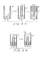
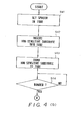
- FIG. 3(a) - (c) A first embodiment of a method of manufacturing the ion sensor is illustrated in Figs. 3(a) - (c) and will now be described in detail with reference to the flowchart of Fig. 4 (a), (b).
- a spacer 19 having the thickness D of the membrane at the sensitive portion 17 is set in the tube 14, as shown at the extreme left of Fig. 3(a).
- the central portion of the spacer 19 is formed to have a recess capable of readily receiving the distal end of the ion-sensitive substrate 13.
- the ion-sensitive substrate 13 is inserted into and set within the tube 14, as shown at the center of Fig. 3(a). This is followd by steps S43, S44, at which the ion-sensitive substrate is secured to the tube 14 by the insulating adhesive 18.
- the distal end of the tube 14 is pointed upward, as shown on the left side in Fig.
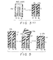
- Fig. 5 is a view for describing a second embodiment of a method of manufacturing an ion sensor according to the present invention.
- steps similar to those shown in Figs. 3(a) - (c) are not illustrated.
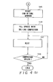
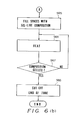
- This second embodiment of the manufacturing method will now be described in detail with reference to the flowchart of Fig. 6 (a), (b).
- the ion-sensitive substrate 13 is inserted into the tube 14 and is recessed from the end of the tube 14 by a sufficient distance X.
- steps S62, S63 the ion-sensitive substrate 13 is secured to the tube 14 by the insulating adhesive 18.
- the distal end of the tube 14 is pointed upward, after which it is filled with the sol-like ion carrier membrane composition 17a at a step S65.
- steps S66, S67 at which the sol-like ion carrier membrane composition 17a is converted into a gelled ion carrier membrane composition 17b by being heated at a temperature 80 - 200 o C.
- steps S68 the distal end of the tube 14 is cut off so that the membrane thickness of the sensitive portion 17 will by the thickness D. This completes the manufacture of the ion sensor 20.
- the method of inserting and setting the ion-sensitive substrate 13 within the tube 14 is not limited to the illustrated embodiments.
- the technique used to coat the ion-sensitive substrate with the ion carrier membrane entails using the tube, inserting the ion-sensitive substrate into the tube, adjusting the positional relationship between them as desired, filling the space between them with the sol-type ion carrier membrane composition, and then gelling the composition. Accordingly, the coating step is simplified, treatment time is shortened and the thickness of the membrane can be readily controlled so that a carrier membrane of a constant thickness can be formed with excellent reproducibility.
- the method is particularly advantageous when manufacturing an ion sensor having an internal electrode of any shape.
- the ion carrier membrane thickness can be set by the user at his discretion.
- Fig. 1 illustrates an ion sensor according to an embodiment of the present invention.
- the ion-sensitive substrate 13 comprises the 1 mm-diameter platinum wire whose peripheral surface is coated with the insulating paint 12.
- the lower-end face 11 (ion-sensitive portion) of the ion-sensitive substrate 13 on the open side of the tube, and the peripheral surface of the lower portion of the ion-sensitive substrate 13, are directly coated with the ion carrier membrane 17 having thicknesses of 2 - 3 mm and 1 mm, respectively.
- the space between the upper portion of the ion-sensitive substrate 13 and the upper portion of the tube 14 is filled with the insulating adhesive (e.g. TB-2067 manufactured by Three Bond Corp.) 18.
- the leading wire e.g. of copper is connected to the upper end of the ion-sensitive substrate 13.
- the following is used as the ion carrier membrane composition, assuming that the ion sensor is for measuring the concentration of potassium ion:
- the valinomycin was dissolved in the o-nitro- phenyloctyl ether, followed by the addition of the dioctylsebacate. Next, the polyvinyl chloride paste resin was added and the mixture was stirred sufficiently. Thereafter, the mixture was defoamed while being stirred for more than 5hr under a pressure lower than 10 -2 mmHg, thereby providing a plastisol-type ion carrier membrane composition. After the plastisol was packed into the electrode end portion 17, heating was effected immediately at a temperature of 140 0 C using an oven, thereby enabling a gell to form in 2 - 5 min.
- the electric potential between the ion sensor and a reference electrode (saturated sodium chloride calomel electrode) 21 was measured, thus providing a measurement of the potassium concentration in a liquid specimen 22.
- a reference electrode saturated sodium chloride calomel electrode
- the potassium concentration in the liquid specimen was changed to 7.5 x 10 -3 M/1, 7.5 x 10 -2 M/l and 7.5 x 10 -1 M/ 1, and the equilibrium potential value was measured for each concentration.
- the equilibrium potentials obtained where 245 mV, 305 mV and 360 mV, respectively, and a straight line (linear relationship) satisfying a Nernst equation was obtained from the correlation among these potential values. From the slope of the straight line, 58 mV/log ([K + ]/mol dm -3 ) was obtained.
- the speed of response time was less than 60 sec.
- An ion sensor was manufactured as in Example 1, the only difference being that a silver wire having a diameter of 1 mm was used in place of the platinum wire.
- the ion sensor with the silver wire was used to measure potassium ion concentration in the manner described above.
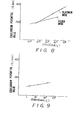
- the results are shown in Figs. 7 and 8.
- the results shown in Fig. 7 are for measurement performed continuously for 10 hr in a 50 ml KCl solution having a concentration of 1.5 x 10⁻⁴ M/ l.
- Fig. 8 shows the results obtained when the potassium ion concentration in the liquid specimen was changed to 2 x 10 4 M/ 1 - 9 x 10 2 M/ l. From the slope of the straight line shown in Fig. 8, 30 mV/log ([K + ]/mol dm -3 ) was obtained.
- a sodium ion sensor using a silver wire having a diameter of 1 mm was manufactured as in Example 2, the only difference being that the wire was coated with a sodium ion carrier membrane, rather than a potassium ion carrier membrane, in which a paste-like polyvinyl chloride was used as a base polymer.
- the ion sensor was used to measure sodium ion concentration in a liquid specimen in the manner described above in connection with Example 2. The results are shown in Fig. 9. In this case, the sodium ion concentration in the liquid specimen was changed to 1 M/1 - 10 3 M/l. From the slope of the straight line shown in Fig. 9, 20mV/decade [Na + ] /mol dm -3 (25°C + 0.1°C) was obtained.
- the sodium ion carrier membrane composition in this example was as follows:
- Basal plane pyrolytic graphite (BPG) having a diameter of 1.3 mm was used in place of the platinum wire of Example 1.
- BPG Basal plane pyrolytic graphite
- This plastisol was gelled by being heated at a temperature of 140°C for 5 min to form a polyvinyl chloride membrane having a thickness of 1 mm.
- One end of the BPG was bonded to the leading wire beforehand by using an electrically conductive adhesive (C-850-6 manufactured by Amicon K.K.).
- the electromotive force of the sensor thus formed was measured at a temperature of 37°C while the potassium concentration in the liquid specimen was changed from 5 x 10 4 to 1 mol/l.
- the electromotive force was linear, as illustrated in Fig. 10, with the slope of the straight line being 57 mV/log [K + ]/mol dm -3 , The time needed for a 95% response was less than 1 min in the range 10 -3 - 10° M.
- Example 5 sodium ion sensor
- plastisol serving as a sodium ion carrier membrane was formed on the surface of the BPG electrode to a thickness of 1 mm under conditions the same as those used in Example 4.
- the sodium ion carrier membrane composition was as follows:
- the electromotive force of this electrode was measured at a temperature of 37°C while the sodium ion concentration was changed using a 1 mM - 1 M NaCl solution. As a result, good linearity was obtained between the electromotive force and the sodium ion concentration, and the slope of the straight line was 57 mV/log [Na + ]/mol dm -3 . The time needed for 90% response was less than 1 min.
- the ion carrier membrane thickness of the sensitive portion of the ion-sensitive substrate is taken as being 2 - 3 mm. In general, however, the membrane thickness can be selected within the range 50 um - 3 mm.
- the ion-sensitive substrate is not limited to that mentioned above but can be a member comprising silver/silver chloride or palladium, a carbon electrode whose surface is coated with these substances, a semiconductor (Sn0 2 , In 2 0 3 , SiC, etc.) or a carbon electrode.
- the ions measured are not limited to potassium and sodium ion; concentrations of other ions can be measured by suitably selecting the ion carrier membrane.
- the tube (designated at numeral 14 in Fig. 1) covering the ion carrier membrane is preferred in view of improving the durability and stability of the ion sensor, the tube can be deleted depending upon the circumstances.
- the ion sensor of the present invention is adapted to measure an ion of interest via a comparatively thick ion carrier membrane selectively permeable to the particular ion, measurement is influenced neither by coexisting ions in the liquid specimen nor by pulsation of the liquid specimen. In addition, a quick response to the ion of interest is obtained.
- the apparatus can be made very small in size and improved in durability, and there is not danger of leakage since, unlike the prior art, the sensor does not require an internal chamber.
- the ion sensor of the present invention can also be used upon beinq incorporated in various ion meters.
Landscapes
- Chemical & Material Sciences (AREA)
- Life Sciences & Earth Sciences (AREA)
- Health & Medical Sciences (AREA)
- Biochemistry (AREA)
- Chemical Kinetics & Catalysis (AREA)
- Electrochemistry (AREA)
- Physics & Mathematics (AREA)
- Analytical Chemistry (AREA)
- Molecular Biology (AREA)
- General Health & Medical Sciences (AREA)
- General Physics & Mathematics (AREA)
- Immunology (AREA)
- Pathology (AREA)
- Investigating Or Analyzing Materials By The Use Of Fluid Adsorption Or Reactions (AREA)
- Measurement Of The Respiration, Hearing Ability, Form, And Blood Characteristics Of Living Organisms (AREA)
- Other Investigation Or Analysis Of Materials By Electrical Means (AREA)
Applications Claiming Priority (4)
| Application Number | Priority Date | Filing Date | Title |
|---|---|---|---|
| JP113667/85 | 1985-05-27 | ||
| JP11366785 | 1985-05-27 | ||
| JP12566585 | 1985-06-10 | ||
| JP125665/85 | 1985-06-10 |
Publications (3)
| Publication Number | Publication Date |
|---|---|
| EP0203864A2 true EP0203864A2 (fr) | 1986-12-03 |
| EP0203864A3 EP0203864A3 (en) | 1987-08-05 |
| EP0203864B1 EP0203864B1 (fr) | 1990-05-23 |
Family
ID=26452611
Family Applications (1)
| Application Number | Title | Priority Date | Filing Date |
|---|---|---|---|
| EP86401111A Expired - Lifetime EP0203864B1 (fr) | 1985-05-27 | 1986-05-27 | Capteur d'ions et sa méthode de fabrication |
Country Status (5)
| Country | Link |
|---|---|
| US (1) | US4753719A (fr) |
| EP (1) | EP0203864B1 (fr) |
| JP (1) | JPH0668478B2 (fr) |
| KR (1) | KR900008847B1 (fr) |
| DE (1) | DE3671530D1 (fr) |
Cited By (5)
| Publication number | Priority date | Publication date | Assignee | Title |
|---|---|---|---|---|
| EP0306802A1 (fr) * | 1987-09-10 | 1989-03-15 | Miles Inc. | Ethers couronnes chiraux |
| EP0270751A3 (fr) * | 1986-12-11 | 1989-10-04 | Horiba, Ltd. | Solution d'électrolyte pour usage dans des électrodes pour la mesure d'ions et son procédé de fabrication |
| EP0393184A4 (en) * | 1987-03-27 | 1991-03-20 | Terumo Kabushiki Kaisha | Ion sensor |
| WO1995022052A1 (fr) * | 1994-02-11 | 1995-08-17 | Ecossensors Limited | Detection de la presence de plomb dans le sang |
| WO1996024840A1 (fr) * | 1995-02-10 | 1996-08-15 | Ecossensors Limited | Mesure des ions metal dans une solution |
Families Citing this family (14)
| Publication number | Priority date | Publication date | Assignee | Title |
|---|---|---|---|---|
| WO1988000700A1 (fr) * | 1986-07-10 | 1988-01-28 | Terumo Kabushiki Kaisha | Electrode de reference |
| JPS63131056A (ja) * | 1986-11-20 | 1988-06-03 | Terumo Corp | Fet電極 |
| CA1315927C (fr) * | 1986-12-10 | 1993-04-13 | Terumo Kabushiki Kaisha | Membrane ionique et chambre d'ionisation comportant cette membrane |
| US5156728A (en) * | 1987-02-12 | 1992-10-20 | Terumo Kabushiki Kaisha | Ion sensor |
| JP2672561B2 (ja) * | 1988-01-29 | 1997-11-05 | テルモ株式会社 | 膜被履センサ |
| JPH01272957A (ja) * | 1988-04-25 | 1989-10-31 | Terumo Corp | イオン感応膜、その製造方法及びイオンセンサ |
| US5066383A (en) * | 1988-10-27 | 1991-11-19 | Terumo Kabushiki Kaisha | Reference electrode, ion sensor and method of manufacturing the same |
| US5213675A (en) * | 1988-10-27 | 1993-05-25 | Terumo Kabushiki Kaisha | Reference electrode, ion sensor and method of manufacturing the same |
| US5401377A (en) * | 1993-08-06 | 1995-03-28 | Biomedix, Inc. | Ion-selective sensor with polymeric membrane having phospholipid dispersed therein |
| US5626331A (en) * | 1996-01-03 | 1997-05-06 | Erwin Industries, Inc. | Composite spindle |
| FR2752380B1 (fr) * | 1996-08-14 | 1998-10-30 | Dow Corning Sa | Procede de fabrication d'un dispositif a liberation controlee |
| US7695601B2 (en) * | 2006-05-09 | 2010-04-13 | The United States Of America As Represented By The Secretary Of The Army | Electrochemical test apparatus and method for its use |
| GB2441784A (en) * | 2006-09-13 | 2008-03-19 | Rtc North Ltd | Device for obtaining and analysing a biological fluid |
| US20120223457A1 (en) * | 2011-03-01 | 2012-09-06 | General Electric Company | Method to manufacture a sensor |
Family Cites Families (15)
| Publication number | Priority date | Publication date | Assignee | Title |
|---|---|---|---|---|
| US3926764A (en) * | 1971-05-19 | 1975-12-16 | Radiometer As | Electrode for potentiometric measurements |
| US3957612A (en) * | 1974-07-24 | 1976-05-18 | General Electric Company | In vivo specific ion sensor |
| US3957613A (en) * | 1974-11-01 | 1976-05-18 | General Electric Company | Miniature probe having multifunctional electrodes for sensing ions and gases |
| US4052285A (en) * | 1975-03-20 | 1977-10-04 | National Research Development Corporation | Ion selective electrodes |
| US4214968A (en) * | 1978-04-05 | 1980-07-29 | Eastman Kodak Company | Ion-selective electrode |
| JPS57142356U (fr) * | 1981-02-28 | 1982-09-07 | ||
| JPS57196116A (en) * | 1981-05-27 | 1982-12-02 | Kamachiyou Seikou Kk | Measuring device |
| US4563263A (en) * | 1982-01-15 | 1986-01-07 | Terumo Corporation | Selectively permeable film and ion sensor |
| JPS599550A (ja) * | 1982-07-09 | 1984-01-18 | Toshiba Corp | イオン選択性電極 |
| JPS5916987A (ja) * | 1982-07-20 | 1984-01-28 | Olympus Optical Co Ltd | クロ−ルイオン選択性電極の製造方法 |
| JPS5957156A (ja) * | 1982-09-28 | 1984-04-02 | Toshiba Corp | イオン選択性電極 |
| JPS607357A (ja) * | 1983-06-28 | 1985-01-16 | Tokuyama Soda Co Ltd | 電極用膜 |
| US4549951A (en) * | 1984-09-11 | 1985-10-29 | Sentech Medical Corporation | Ion selective electrode |
| EP0186210B1 (fr) * | 1984-12-28 | 1992-04-22 | TERUMO KABUSHIKI KAISHA trading as TERUMO CORPORATION | Senseur d'ions |
| CN1366796A (zh) * | 2000-02-10 | 2002-08-28 | 皇家菲利浦电子有限公司 | 切换式调暗镇流器 |
-
1986
- 1986-05-26 KR KR1019860004112A patent/KR900008847B1/ko not_active Expired
- 1986-05-27 EP EP86401111A patent/EP0203864B1/fr not_active Expired - Lifetime
- 1986-05-27 DE DE8686401111T patent/DE3671530D1/de not_active Expired - Fee Related
- 1986-05-27 JP JP61120179A patent/JPH0668478B2/ja not_active Expired - Fee Related
- 1986-05-27 US US06/866,738 patent/US4753719A/en not_active Expired - Lifetime
Cited By (6)
| Publication number | Priority date | Publication date | Assignee | Title |
|---|---|---|---|---|
| EP0270751A3 (fr) * | 1986-12-11 | 1989-10-04 | Horiba, Ltd. | Solution d'électrolyte pour usage dans des électrodes pour la mesure d'ions et son procédé de fabrication |
| EP0393184A4 (en) * | 1987-03-27 | 1991-03-20 | Terumo Kabushiki Kaisha | Ion sensor |
| EP0306802A1 (fr) * | 1987-09-10 | 1989-03-15 | Miles Inc. | Ethers couronnes chiraux |
| WO1995022052A1 (fr) * | 1994-02-11 | 1995-08-17 | Ecossensors Limited | Detection de la presence de plomb dans le sang |
| US5814205A (en) * | 1994-02-11 | 1998-09-29 | Palintest Limited | Detection of lead in blood |
| WO1996024840A1 (fr) * | 1995-02-10 | 1996-08-15 | Ecossensors Limited | Mesure des ions metal dans une solution |
Also Published As
| Publication number | Publication date |
|---|---|
| JPH0668478B2 (ja) | 1994-08-31 |
| US4753719A (en) | 1988-06-28 |
| EP0203864A3 (en) | 1987-08-05 |
| KR900008847B1 (ko) | 1990-11-30 |
| DE3671530D1 (de) | 1990-06-28 |
| KR860009304A (ko) | 1986-12-22 |
| EP0203864B1 (fr) | 1990-05-23 |
| JPS6290531A (ja) | 1987-04-25 |
Similar Documents
| Publication | Publication Date | Title |
|---|---|---|
| EP0203864A2 (fr) | Capteur d'ions et sa méthode de fabrication | |
| Hill et al. | Flexible valinomycin electrodes for on-line determination of intravascular and myocardial K+ | |
| US4214968A (en) | Ion-selective electrode | |
| EP0125807B1 (fr) | Appareil sensible au PH et au C02 | |
| EP0551769B1 (fr) | Electrodes solides à sélectivité ionique à base de graphite avec membrane polymère | |
| EP0247941B1 (fr) | Capteur de gaz | |
| US5401377A (en) | Ion-selective sensor with polymeric membrane having phospholipid dispersed therein | |
| JPS6020700B2 (ja) | 電極の対を支持するフレ−ム | |
| JPS584981B2 (ja) | イオン選択性電極 | |
| JP2003533694A (ja) | イオン選択的固体状態ポリマー膜電極 | |
| US5078856A (en) | Ion carrier membrane, and ion sensor having same | |
| JP2003525450A (ja) | 固体状態参照系を持つ電極デバイス | |
| US7384523B2 (en) | Chloride ion selective membrane and sensor | |
| AU639005B2 (en) | Electrochemical cell, reference electrode and electrochemical method | |
| GB1565988A (en) | Nitrate ion-containing selective electrode | |
| JP2001514760A (ja) | サブミニアチュアスルーホールを備えたワイアリングサブストレートの製造方法 | |
| EP0683390A1 (fr) | Electrode ampèrométrique sélective à l'égard des ions | |
| US20020038762A1 (en) | Solid-state ion selective electrodes and methods of producing the same | |
| CA1116696A (fr) | Electrode a selection ionique | |
| Lemke et al. | Coated film electrodes | |
| KR0155038B1 (ko) | 이온 선택성 막 및 그 제조방법 | |
| JP2599819Y2 (ja) | 測定電極 | |
| JPH0328928B2 (fr) | ||
| EP0358761B1 (fr) | Electrode | |
| JPH03172751A (ja) | 銀・銀化合物電極およびその製造方法 |
Legal Events
| Date | Code | Title | Description |
|---|---|---|---|
| PUAI | Public reference made under article 153(3) epc to a published international application that has entered the european phase |
Free format text: ORIGINAL CODE: 0009012 |
|
| 17P | Request for examination filed |
Effective date: 19860729 |
|
| AK | Designated contracting states |
Kind code of ref document: A2 Designated state(s): BE DE FR GB NL SE |
|
| RIN1 | Information on inventor provided before grant (corrected) |
Inventor name: USHIZAWA, NORIHIKO Inventor name: SHIMOMURA, TAKESHI Inventor name: YAMAGUCHI, SHUICHIRO |
|
| PUAL | Search report despatched |
Free format text: ORIGINAL CODE: 0009013 |
|
| RAP1 | Party data changed (applicant data changed or rights of an application transferred) |
Owner name: TERUMO KABUSHIKI KAISHA TRADING AS TERUMO CORPORAT |
|
| AK | Designated contracting states |
Kind code of ref document: A3 Designated state(s): BE DE FR GB NL SE |
|
| 17Q | First examination report despatched |
Effective date: 19880325 |
|
| GRAA | (expected) grant |
Free format text: ORIGINAL CODE: 0009210 |
|
| AK | Designated contracting states |
Kind code of ref document: B1 Designated state(s): BE DE FR GB NL SE |
|
| REF | Corresponds to: |
Ref document number: 3671530 Country of ref document: DE Date of ref document: 19900628 |
|
| ET | Fr: translation filed | ||
| PLBE | No opposition filed within time limit |
Free format text: ORIGINAL CODE: 0009261 |
|
| STAA | Information on the status of an ep patent application or granted ep patent |
Free format text: STATUS: NO OPPOSITION FILED WITHIN TIME LIMIT |
|
| 26N | No opposition filed | ||
| EAL | Se: european patent in force in sweden |
Ref document number: 86401111.9 |
|
| REG | Reference to a national code |
Ref country code: GB Ref legal event code: IF02 |
|
| PGFP | Annual fee paid to national office [announced via postgrant information from national office to epo] |
Ref country code: SE Payment date: 20030507 Year of fee payment: 18 |
|
| PGFP | Annual fee paid to national office [announced via postgrant information from national office to epo] |
Ref country code: FR Payment date: 20030508 Year of fee payment: 18 |
|
| PGFP | Annual fee paid to national office [announced via postgrant information from national office to epo] |
Ref country code: GB Payment date: 20030519 Year of fee payment: 18 |
|
| PGFP | Annual fee paid to national office [announced via postgrant information from national office to epo] |
Ref country code: NL Payment date: 20030530 Year of fee payment: 18 |
|
| PGFP | Annual fee paid to national office [announced via postgrant information from national office to epo] |
Ref country code: DE Payment date: 20030605 Year of fee payment: 18 |
|
| PGFP | Annual fee paid to national office [announced via postgrant information from national office to epo] |
Ref country code: BE Payment date: 20030725 Year of fee payment: 18 |
|
| PG25 | Lapsed in a contracting state [announced via postgrant information from national office to epo] |
Ref country code: GB Free format text: LAPSE BECAUSE OF NON-PAYMENT OF DUE FEES Effective date: 20040527 |
|
| PG25 | Lapsed in a contracting state [announced via postgrant information from national office to epo] |
Ref country code: SE Free format text: LAPSE BECAUSE OF NON-PAYMENT OF DUE FEES Effective date: 20040528 |
|
| PG25 | Lapsed in a contracting state [announced via postgrant information from national office to epo] |
Ref country code: BE Free format text: LAPSE BECAUSE OF NON-PAYMENT OF DUE FEES Effective date: 20040531 |
|
| BERE | Be: lapsed |
Owner name: *TERUMO K.K. TRADING AS TERUMO CORP. Effective date: 20040531 |
|
| PG25 | Lapsed in a contracting state [announced via postgrant information from national office to epo] |
Ref country code: NL Free format text: LAPSE BECAUSE OF NON-PAYMENT OF DUE FEES Effective date: 20041201 Ref country code: DE Free format text: LAPSE BECAUSE OF NON-PAYMENT OF DUE FEES Effective date: 20041201 |
|
| EUG | Se: european patent has lapsed | ||
| GBPC | Gb: european patent ceased through non-payment of renewal fee | ||
| PG25 | Lapsed in a contracting state [announced via postgrant information from national office to epo] |
Ref country code: FR Free format text: LAPSE BECAUSE OF NON-PAYMENT OF DUE FEES Effective date: 20050131 |
|
| NLV4 | Nl: lapsed or anulled due to non-payment of the annual fee |
Effective date: 20041201 |
|
| REG | Reference to a national code |
Ref country code: FR Ref legal event code: ST |