EP0205975A2 - Robot industriel programmable avec un bras commandé par un moteur avec un activateur variable - Google Patents
Robot industriel programmable avec un bras commandé par un moteur avec un activateur variable Download PDFInfo
- Publication number
- EP0205975A2 EP0205975A2 EP86107276A EP86107276A EP0205975A2 EP 0205975 A2 EP0205975 A2 EP 0205975A2 EP 86107276 A EP86107276 A EP 86107276A EP 86107276 A EP86107276 A EP 86107276A EP 0205975 A2 EP0205975 A2 EP 0205975A2
- Authority
- EP
- European Patent Office
- Prior art keywords
- memory
- arm
- during
- signal
- mode
- Prior art date
- Legal status (The legal status is an assumption and is not a legal conclusion. Google has not performed a legal analysis and makes no representation as to the accuracy of the status listed.)
- Granted
Links
Images



Classifications
-
- B—PERFORMING OPERATIONS; TRANSPORTING
- B25—HAND TOOLS; PORTABLE POWER-DRIVEN TOOLS; MANIPULATORS
- B25J—MANIPULATORS; CHAMBERS PROVIDED WITH MANIPULATION DEVICES
- B25J9/00—Program-controlled manipulators
- B25J9/06—Program-controlled manipulators characterised by multi-articulated arms
-
- G—PHYSICS
- G05—CONTROLLING; REGULATING
- G05B—CONTROL OR REGULATING SYSTEMS IN GENERAL; FUNCTIONAL ELEMENTS OF SUCH SYSTEMS; MONITORING OR TESTING ARRANGEMENTS FOR SUCH SYSTEMS OR ELEMENTS
- G05B19/00—Program-control systems
- G05B19/02—Program-control systems electric
- G05B19/42—Recording and playback systems, i.e. in which the program is recorded from a cycle of operations, e.g. the cycle of operations being manually controlled, after which this record is played back on the same machine
- G05B19/423—Teaching successive positions by walk-through, i.e. the tool head or end effector being grasped and guided directly, with or without servo-assistance, to follow a path
-
- B—PERFORMING OPERATIONS; TRANSPORTING
- B25—HAND TOOLS; PORTABLE POWER-DRIVEN TOOLS; MANIPULATORS
- B25J—MANIPULATORS; CHAMBERS PROVIDED WITH MANIPULATION DEVICES
- B25J13/00—Controls for manipulators
- B25J13/06—Control stands, e.g. consoles, switchboards
-
- B—PERFORMING OPERATIONS; TRANSPORTING
- B25—HAND TOOLS; PORTABLE POWER-DRIVEN TOOLS; MANIPULATORS
- B25J—MANIPULATORS; CHAMBERS PROVIDED WITH MANIPULATION DEVICES
- B25J9/00—Program-controlled manipulators
- B25J9/02—Program-controlled manipulators characterised by movement of the arms, e.g. cartesian coordinate type
- B25J9/04—Program-controlled manipulators characterised by movement of the arms, e.g. cartesian coordinate type by rotating at least one arm, excluding the head movement itself, e.g. cylindrical coordinate type or polar coordinate type
- B25J9/041—Cylindrical coordinate type
- B25J9/042—Cylindrical coordinate type comprising an articulated arm
-
- B—PERFORMING OPERATIONS; TRANSPORTING
- B25—HAND TOOLS; PORTABLE POWER-DRIVEN TOOLS; MANIPULATORS
- B25J—MANIPULATORS; CHAMBERS PROVIDED WITH MANIPULATION DEVICES
- B25J9/00—Program-controlled manipulators
- B25J9/10—Program-controlled manipulators characterised by positioning means for manipulator elements
- B25J9/106—Program-controlled manipulators characterised by positioning means for manipulator elements with articulated links
- B25J9/1065—Program-controlled manipulators characterised by positioning means for manipulator elements with articulated links with parallelograms
- B25J9/107—Program-controlled manipulators characterised by positioning means for manipulator elements with articulated links with parallelograms of the froglegs type
-
- G—PHYSICS
- G05—CONTROLLING; REGULATING
- G05B—CONTROL OR REGULATING SYSTEMS IN GENERAL; FUNCTIONAL ELEMENTS OF SUCH SYSTEMS; MONITORING OR TESTING ARRANGEMENTS FOR SUCH SYSTEMS OR ELEMENTS
- G05B19/00—Program-control systems
- G05B19/02—Program-control systems electric
- G05B19/42—Recording and playback systems, i.e. in which the program is recorded from a cycle of operations, e.g. the cycle of operations being manually controlled, after which this record is played back on the same machine
-
- G—PHYSICS
- G05—CONTROLLING; REGULATING
- G05B—CONTROL OR REGULATING SYSTEMS IN GENERAL; FUNCTIONAL ELEMENTS OF SUCH SYSTEMS; MONITORING OR TESTING ARRANGEMENTS FOR SUCH SYSTEMS OR ELEMENTS
- G05B2219/00—Program-control systems
- G05B2219/30—Nc systems
- G05B2219/36—Nc in input of data, input key till input tape
- G05B2219/36159—Detachable or portable programming unit, display, pc, pda
-
- G—PHYSICS
- G05—CONTROLLING; REGULATING
- G05B—CONTROL OR REGULATING SYSTEMS IN GENERAL; FUNCTIONAL ELEMENTS OF SUCH SYSTEMS; MONITORING OR TESTING ARRANGEMENTS FOR SUCH SYSTEMS OR ELEMENTS
- G05B2219/00—Program-control systems
- G05B2219/30—Nc systems
- G05B2219/36—Nc in input of data, input key till input tape
- G05B2219/36422—During teaching shut off, disable motor to move arm easy
-
- G—PHYSICS
- G05—CONTROLLING; REGULATING
- G05B—CONTROL OR REGULATING SYSTEMS IN GENERAL; FUNCTIONAL ELEMENTS OF SUCH SYSTEMS; MONITORING OR TESTING ARRANGEMENTS FOR SUCH SYSTEMS OR ELEMENTS
- G05B2219/00—Program-control systems
- G05B2219/30—Nc systems
- G05B2219/36—Nc in input of data, input key till input tape
- G05B2219/36429—Power assisted positioning
-
- G—PHYSICS
- G05—CONTROLLING; REGULATING
- G05B—CONTROL OR REGULATING SYSTEMS IN GENERAL; FUNCTIONAL ELEMENTS OF SUCH SYSTEMS; MONITORING OR TESTING ARRANGEMENTS FOR SUCH SYSTEMS OR ELEMENTS
- G05B2219/00—Program-control systems
- G05B2219/30—Nc systems
- G05B2219/36—Nc in input of data, input key till input tape
- G05B2219/36472—During teaching low servo power, during playback high servo power
-
- Y—GENERAL TAGGING OF NEW TECHNOLOGICAL DEVELOPMENTS; GENERAL TAGGING OF CROSS-SECTIONAL TECHNOLOGIES SPANNING OVER SEVERAL SECTIONS OF THE IPC; TECHNICAL SUBJECTS COVERED BY FORMER USPC CROSS-REFERENCE ART COLLECTIONS [XRACs] AND DIGESTS
- Y10—TECHNICAL SUBJECTS COVERED BY FORMER USPC
- Y10S—TECHNICAL SUBJECTS COVERED BY FORMER USPC CROSS-REFERENCE ART COLLECTIONS [XRACs] AND DIGESTS
- Y10S700/00—Data processing: generic control systems or specific applications
- Y10S700/90—Special robot structural element
Definitions
- the present invention relates generally to industrial robots, and more particularly to an industrial robot which allows its arms to be manipulated with a minimum of effort and precision.
- a prior art industrial robot as shown and described in Japanese Utility Model 59-41033, has a hydraulically operated, vertically swingable arm with a spray gun attached to it to perform paint spray operations in accordance with instructions stored in a memory.
- the instructions are initially taught by manipulating the robot arm so that the spray gun is located exactly in positions where paint is applied and translating the robot arm into position data for storage into the memory.
- the memory is addressed to successively read the stored position data to modulate the hydraulic pressure to move the robot arm along the intended path.
- Another prior art industrial robot which is a more recent and general type of industrial robot, employs an electric motor which directly drives the robot arm and a servo-control system which controls the motor in accordance with a difference which exists between a target position and the actual position of the arm.
- the servo-control system is designed to operate at all times and therefore it causes the robot arm to present a substantial amount of resistance to manual effort when it is desired to move it to a teaching position. As a result, it is difficult to achieve precision teaching control.
- This object is attained by reducing the servo-control output to an appropriate value during teaching modes and increasing the servo-control output during playback modes.
- the industrial robot of the invention comprises a position encoder for generating an actual position signal representative of the actual position of the arm, a memory and a manually controlled position entry device operable during a teaching mode.
- a memory controller is responsive to operation of the position entry device when the arm is manually moved to a desired position for storing the actual position signal into the memory as a target position signal indicating the desired position and reading the stored signal during a playback mode.
- a servo-control system responds to the actual position signal from the encoder and the target position signal from the memory by controlling the motor so that the actual position of the arm approaches the desired position during the playback mode.
- the output of the servo-control system is decreased during the teaching mode to render the arm manually movable to the desired position and is increased during the playback mode.
- the servo-control system is disabled during the teaching mode to render the arm manually movabel to the desired position.
- an industrial robot according to a first preferred embodiment of the invention comprises an upper motor 2a mounted on an arm portion of a stand A and a lower motor 2b on the base of the stand.
- Motor 2a has a rotary cylinder 2c connected to it for rotation therewith and motor 2b has a rotary cylinder 2d connected thereto for rotation therewith in coaxial relationship with the upper cylinder.
- An arm la extends horizontally from the upper cylinder 2c and is articulated with an arm lb by means of a roller bearing le, the arm lb being jointed to an arm lc with a roller bearing lf.
- Arm 1c is in turn articulated by a bearing lg with an arm ld which extends from the lower cylinder 2d. It is seen that arms la, lb, lc and Id form a pantograph.
- a robot hand lh which is vertically movable by means of a linear motor li.
- a position encoder 3 is connected to the motor 2a to detect the angular position of arm lb..
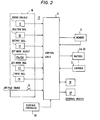
- a teaching device 16 which is connected by a cable 17 to a control unit 6 for entry of instruction data thereinto.
- Teaching device 16 includes plural command controls including servo-unlock command 9, position registration command 10, output signal registration command 11, external mode select command 12, external mode registration command 13, and timer control command 14.
- Teaching device 16 further includes a servo-output control command 15 through which a voltage is supplied to control unit 6.
- Control unit 6 processes the input command data and stores its results into a memory 5 and controls motors 2a, 2b in accordance with the stored data.
- the voltage supplied to motors 2a, 2b is controlled at high or low voltage depending on the operation of the servo-control command 15.
- External devices 18 and 19 are connected to the control unit 6 to receive command signals therefrom.
- Device 18 is of an interactive type which supplies a signal to the control unit indicating its operating mode, whereas device 19 provides no mode signal.
- a playback controller 30 is coupled to the control unit 6 to cause it to operate the robot in a playback mode in which the arm 1 is moved along instructed paths in accordance with a stored program in a manner well known in the art.
- the teaching device 16 is of a generally L-shaped construction with a hand-grip portion 23 on which the servo-unlock command 9 is located for ease of manipulation. All the command controls except command switch 9 are arranged on top of the device 16 within the reach of an operator's finger while holding the grip-portion 23. This permits the robot arms to be moved by a single hand while holding the teaching device with the other hand, giving a freedom to teaching operation.
- Teaching device 16 is detachably mounted by a pair of couplers 20 to the arm 1. Cable 17 is detachably connected by a connector 21 on the arm 1 to the control unit 6. Connector 21 serves the function of on-off command 15. Indicator lamps 22 are provided for indicating the operating conditions of mode select commands 12a and 12b. Teaching device 16 is dismantled from the robot before it is played back in accordance with registered information to reduce the load on the robot arms and prevents unauthorized personnel from entering false information into the teachig device.
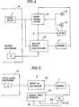
- control unit 6 includes a servo control circuit 6a which receives inputs from memory 5 and position encoder 3 and controls the motors 2a and 2b in accordance with the difference between the actual position of arm lb and a target position represented by the data read out of memory 5 through a closed servo-control loop.
- the servo-control loop is disabled in response to an output from the servo-unlock command 9 to deactivate the motors 2a and 2b. This allows the operator to manipulate the robot arms with a minimum of effort.
- a position signal registration circuit 6b is enabled by the position signal registration command 10 to discriminate the output of the servo-unlock command 9 and characterizes the position signal from encoder 3 depending on whether the servo-unlock command 9 is operated or not in a manner as will be detailed later.
- the characterized position signal is stored into memory 5.
- various control data can be advantageously stored into memory 5 as follows.
- an output signal registration circuit 6d is responsive to the output signal registration command 11 to store control data neccesary for the operation of external device 18.
- the command data is retrieved from memory 5 into an external device controller 6e which in turn supplies a control signal on lead 18a to external device 18 for the execution of a specified function.
- External device 18 returns a response on lead 18b to the external device controller 6e, whereupon it proceeds to retrieve the control signal for the execution of the next function.
- the control unit 6 includes an external mode registration circuit 6f connected to the external mode registration command 13 and an external device controller 6g connected to the outputs of external mode select commands 12a and 12b.
- external device controller 6g causes the external device 19 to change operating positions according to the selected external mode.
- External mode registration circuit 6f responds to the operation of external mode registration command 13 by transferring the same mode control data as supplied to the external device 19 to memory 5. In playback, the mode control data is retrieved from memory 5 into the external device controller 6g which controls the device 19 in accordance with the retrieved data.
- a timer registration circuit 6g measures the length of time during which the timer command 14 is depressed and stores the measured time length signal into memory 5. This teaching operation is effected so that on playback there is a time delay between specified operations.
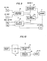
- a coincidence detector 6i is responsive to the position signal registration command 10 and to the output signal registration command 11 to determine whether these command controls are operated individually or simultaneously. If these commands are simultaneously operated, the coincidence detector 6i directs a position signal registration circuit 6j to characterize the output of position encoder 3 in a manner as described in connection with Fig. 4 and store the characterized position signal into memory 5. Immediately after the registration of the characterized position signal, detector 6i directs an output signal registration circuit 6k to store an external device control data into a storage location of memory 5 which is adjacent the location into which the characterized position signal has been registered.
- detector 6i directs the position signal registration circuit 6j exclusively to store characterized position signal into memory 5, and if the output signal registration command 11 is operated exclusively, detector 6i exclusively directs the output signal registration circuit 6k to store the external device control data into memory 5.
- Fig. 8 is modified as shown in Fig. 9 in which a coincidence detector 6 1 is responsive to the position signal registration command 10 and the mode signal registration command 13 to determine if these commands are operated individually or simultaneously.
- simultaneous operation of commands 10 and 13 causes the detector 6 1 to sequentially direct the position signal registration circuit 6j to store its output into memory 5 and enables an external mode registration circuit 6m for registration of an external mode into memory 5.
- an external device controller 6n detects the indication given by one of the mode select commands 12a and 12b which is operated and directs the external mode registration circuit 6m to store the information given by the operated command 12 into memory 5.
- individual operation of commands 10 and 13 causes the detector 6l to respectively directs the associated registration circuits.
- the control unit 6 includes a servo-voltage controller 6 0 which is connected to voltage source via on-off command 15, or connector 21, to detect whether the teaching device 16 is connected to the control unit 6 by connector 21. If the connector 21 is connected, the voltage at the input of controller 6o is high and controller 6 0 directs the servo-control system 6a to operate the motors 2a, 2b at a low voltage. This allows the robot arms to be moved smoothly by the operator's hand. The robot can thus be taught with precision without the possibility of hazard to the operator. If the connector 21 is removed from the robot, the input of controller 60 is low and the latter directs the servo-control system 6a to switch the operating voltage of motors 2a, 2b to normal, high voltage level for playback operations.
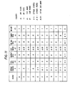
- Teaching mode A is initiated by operation of servo-unlock command 9 (see Fig. 4). Motors 2a, 2b are unlocked from the serve-control system and robot arms la-ld are manually moved until the robot hand lh comes precisely to a desired point. With the robot arms being moved to the desired position, restoration of servo-unlock command 9 will cause the teaching mode to switch to mode B during which the servo-control system 6a is again rendered active, so that motors 2a, 2b are energized with high voltage to keep the robot hand in the desired point.
- a teaching mode C is initiated in which the position signal registration citcuit 6b reads the output of position encoder 3 and for purposes of storage into memory 5 it characterizes the position signal with a signifying code which indicates that the point given by the position signal is a point located on a path traced by the robot hand.
- a teaching mode D is effected.
- the position signal registration circuit 6b interprets the output of encoder 3 that the position it indicates is a point at which the robot hand is to be stopped and characterizes it with an appropriate signifying code for storage into memory 5.
- the amount of positional information stored in memory 5 can be reduced advantageously for efficient use of memory 5.
- the reduction of such information also results in the reduction of time for processing the positional information during playback.
- a further advantage of the characterization is that it allows the positional information to be readily classified advantageously for editing purposes.
- output signal registration command 11 initiates a teaching mode E in which the output signal registration circuit 6d, Fi g . 5, responds to the output of command 11 by generating data for controlling external device 18 and storing it into memory 5.
- Such output-signal registration commands and their associated registration circuits may be provided as many as desired for operating a plurality of external devices. With the servo-control system 6a being unlocked, such registration commands 11 can selectively be operated for instant registration of external device control data while manipulating the robot arms for registration of positional data using position registration command 10.
- Switching operation of external mode select command 12 initiates a teaching mode F in which the external device controller 6g, Fig. 6, selects one of operating positions of the external device 19 in accordance with the switched position of command 12 and supplies it with a selected operating signal to cause it to change operating states. By doing so, it is possible for the operator to test to see if the operating position of the selected external device 19 is optimum for the robot arms. If the operating position of the external device 19 is not optimum for the robot arms, the select command 12 is switched to the next to seek an optimum operating position. The operating signal is also applied to external mode registration circuit 6f for storing the selected position signal into memory 5 in response to operation of registration command 13 when the optimum position is finally determined (mode G). In playback, the stored external mode signal is read from memory 5 into external device 19 through controller 19.
- the external mode teaching operation can therefore be performed simultaneously with ease while the robot arms are manipulated in a manner described above.
- Operation of the timer command 14 initiates a teaching mode H in which the timer registration circuit 6h, Fig. 7, measures the length of time the timer command 14 is manually pressed down and registers a time-length code into memory 5.
- Teaching mode H is advantageously performed between successive command operations during teaching modes E, F and 3, so that, in playback, external device 18 or 19 is taught to perform operations with delays between successive novements.
- Simultaneous operation of position signal registration command 10 and output signal registration command 11 initiates a teaching mode I in which the coincidence detector 6i, Fig. 8, sequentially controls the position signal registration circuit 6j and output signal registration circuit 6k to store the respective outputs into memory 5.
- the robot arms are moved to the position specified by the registration command 10, whereupon the output signal registration circuit 6k reads the stored output signal from memory 5 into external device 18 to cause it to perform the specified operation.
- Robot arms may or may not continue to move after reaching the specified position.
- an extra command switch may be provided on the teaching device 16 to simultaneously operate command keys 10 and 11.
- Teaching mode I can also be performed simultaneously with the manipulation of robot arms.
- a teaching mode K is initiated in which the servo-voltage controller 6o directs the servo-control system 6a to supply a high voltage to motors 2a, 2b.
- the controller 6o directs the servo-control system 6a to supply a low voltage to the motors. This ensures easy movement of the robot arms and safety against possible erratic movements of the robot arms beyond calculated bounds which might occur during teaching modes.
- plural power cut-off switches may be provided in parallel with each other, so that the motors are operated with high voltage only when these switches are open at the same time.
- Fig. 12 is an illustration of a modified form of the teaching device 16 in which parts corresponding to those in Fig. 3 are marked with the same numerals as used in Fig. 3.
- a horizontal extension plate 24 extends from a side wall of robot arm lb.
- Teaching device 16 has a hand-grip portion 26 which is coupled by a joint 27 which permits the teaching device to rotate about the vertical axis of the grip portion 26.
- a connector mount 28 is attached to a side wall of the extension plate 24 to temporarily hold the connector 21 when it is disconnected from the socket 21a.
- Rotary joint 27 advantageously allows the controls of teaching device 16 to orient toward the operator at all times while the orientation of the arm lb is changed to teach the robot.
Landscapes
- Engineering & Computer Science (AREA)
- Robotics (AREA)
- Mechanical Engineering (AREA)
- Physics & Mathematics (AREA)
- General Physics & Mathematics (AREA)
- Automation & Control Theory (AREA)
- Manipulator (AREA)
- Numerical Control (AREA)
Applications Claiming Priority (2)
| Application Number | Priority Date | Filing Date | Title |
|---|---|---|---|
| JP60116921A JPS621004A (ja) | 1985-05-30 | 1985-05-30 | ロボツト |
| JP116921/85 | 1985-05-30 |
Publications (3)
| Publication Number | Publication Date |
|---|---|
| EP0205975A2 true EP0205975A2 (fr) | 1986-12-30 |
| EP0205975A3 EP0205975A3 (en) | 1987-11-19 |
| EP0205975B1 EP0205975B1 (fr) | 1991-07-31 |
Family
ID=14698964
Family Applications (1)
| Application Number | Title | Priority Date | Filing Date |
|---|---|---|---|
| EP86107276A Expired - Lifetime EP0205975B1 (fr) | 1985-05-30 | 1986-05-28 | Robot industriel programmable avec un bras commandé par un moteur avec un activateur variable |
Country Status (5)
| Country | Link |
|---|---|
| US (1) | US4737697A (fr) |
| EP (1) | EP0205975B1 (fr) |
| JP (1) | JPS621004A (fr) |
| KR (1) | KR890000716B1 (fr) |
| DE (1) | DE3680591D1 (fr) |
Cited By (7)
| Publication number | Priority date | Publication date | Assignee | Title |
|---|---|---|---|---|
| EP0298427A1 (fr) * | 1987-07-09 | 1989-01-11 | Kabushiki Kaisha Yaskawa Denki Seisakusho | Bras de robot à barres parallèles |
| EP0391216A1 (fr) * | 1989-04-03 | 1990-10-10 | Mitsubishi Jukogyo Kabushiki Kaisha | Robot de type à apprentissage direct |
| EP0333874A4 (en) * | 1987-09-22 | 1992-06-17 | Fanuc Ltd | Apparatus for controlling industrial robot |
| EP0473927A3 (en) * | 1990-09-06 | 1992-10-21 | Maschinenfabrik Reichenbacher Gmbh | Sculpture copying machine |
| EP0442772A3 (en) * | 1990-02-16 | 1994-06-08 | Mitsubishi Heavy Ind Ltd | Direct teaching type robot |
| WO1997002515A1 (fr) * | 1995-07-03 | 1997-01-23 | Nsm Aktiengesellschaft | Procede et appareil de positionnement d'un moteur pas-a-pas pour un appareil de reproduction, d'enregistrement et/ou d'extraction de disques |
| WO2014071989A1 (fr) * | 2012-11-09 | 2014-05-15 | Abb Technology Ltd | Commande de robot ayant une plus grande sécurité |
Families Citing this family (29)
| Publication number | Priority date | Publication date | Assignee | Title |
|---|---|---|---|---|
| JPH02277102A (ja) * | 1989-04-18 | 1990-11-13 | Toshiba Mach Co Ltd | 数値制御工作機械における加工プログラムティーチング方式 |
| US5122720A (en) * | 1989-12-01 | 1992-06-16 | Martinsound Technologies, Inc. | Automated fader system |
| JPH03190688A (ja) * | 1989-12-19 | 1991-08-20 | Fanuc Ltd | ロボット非常停止回路 |
| US5425133A (en) * | 1990-01-24 | 1995-06-13 | Canon Kabushiki Kaisha | Robot apparatus with an electrical driver for controlling a detachable rotor hand |
| US5086400A (en) * | 1990-05-11 | 1992-02-04 | The United States Of America As Represented The The Administrator Of The National Aeronautics And Space Administration | Bilevel shared control for teleoperators |
| US5101472A (en) * | 1990-10-04 | 1992-03-31 | Repperger Daniel W | Military robotic controller with majorizing function and nonlinear torque capability |
| DE69229670T2 (de) * | 1992-04-01 | 2000-01-27 | Penguin Wax Co. Ltd., Osaka | Bodenbehandlungsmaschine |
| JPH06332538A (ja) * | 1993-05-19 | 1994-12-02 | Fanuc Ltd | 柔軟なサーボ制御方法 |
| JP3283650B2 (ja) * | 1993-07-05 | 2002-05-20 | ファナック株式会社 | ロボット制御装置 |
| JP3804994B2 (ja) * | 1994-07-15 | 2006-08-02 | ファナック株式会社 | ロボットの教示方法 |
| IL120889A (en) | 1997-05-22 | 1998-10-30 | Eshed Robotec 1982 Ltd | Method and facility for direct learning of vending machines |
| KR20040007502A (ko) * | 2001-04-22 | 2004-01-24 | 뉴로닉스 악티엔 게젤샤프트 | 벤딩 암 로벗 |
| US20050053909A1 (en) * | 2003-09-08 | 2005-03-10 | Chan Kwok Hung | Learn-and-play programming method for motorized toys and domestic appliances |
| US7366773B2 (en) * | 2006-01-30 | 2008-04-29 | Dgi Creations, Llc | Alternative communications paths for data sent over power line carrier |
| US20100188034A1 (en) * | 2009-01-23 | 2010-07-29 | Derek Young | Trainable Robot and Method of Training |
| WO2010088959A1 (fr) * | 2009-02-06 | 2010-08-12 | Abb Technology Ab | Procédé de programmation manuelle d'un robot industriel |
| US8204623B1 (en) * | 2009-02-13 | 2012-06-19 | Hrl Laboratories, Llc | Planning approach for obstacle avoidance in complex environment using articulated redundant robot arm |
| WO2011018117A1 (fr) * | 2009-08-14 | 2011-02-17 | Abb Technology Ab | Robot industriel et procédé pour ajuster un programme de robot |
| JP6527655B2 (ja) * | 2013-03-25 | 2019-06-05 | 株式会社デンソーウェーブ | アームの操作方法及び操作装置 |
| TWD172241S (zh) * | 2014-10-10 | 2015-12-01 | 鴻海精密工業股份有限公司 | 機器人 |
| US9804593B1 (en) * | 2014-12-12 | 2017-10-31 | X Development Llc | Methods and systems for teaching positions to components of devices |
| DE102015117213B4 (de) * | 2015-10-08 | 2020-10-29 | Kastanienbaum GmbH | Roboterarm |
| CN108340351B (zh) * | 2018-01-31 | 2023-05-05 | 广东工业大学 | 一种机器人示教装置、方法及示教机器人 |
| JP6698733B2 (ja) * | 2018-04-06 | 2020-05-27 | ファナック株式会社 | モータエンコーダ及びセンサを用いて学習制御を行うロボットシステム |
| JP7567534B2 (ja) * | 2021-02-10 | 2024-10-16 | セイコーエプソン株式会社 | ロボットシステム |
| JP7595491B2 (ja) * | 2021-03-15 | 2024-12-06 | 株式会社ジャノメ | 卓上ロボット |
| US20230122989A1 (en) * | 2021-10-19 | 2023-04-20 | Techman Robot Inc. | Safety system and method for teaching a robot |
| EP4523053A1 (fr) | 2022-05-13 | 2025-03-19 | Abb Schweiz Ag | Fonctions de sécurité dans un robot industriel |
| USD997223S1 (en) * | 2023-06-07 | 2023-08-29 | Primate Robot Hong Kong Co., Limited | Robot |
Family Cites Families (10)
| Publication number | Priority date | Publication date | Assignee | Title |
|---|---|---|---|---|
| NO131906C (fr) * | 1973-02-13 | 1975-08-20 | Trallfa Nils Underhaug As | |
| GB1418710A (en) * | 1973-12-19 | 1975-12-24 | Pye Ltd | Automatic manipulating apparatus |
| FR2464803A1 (fr) * | 1979-09-14 | 1981-03-20 | Devilbiss Toussaint | Procede pour la programmation de robots par action volontaire sur leurs organes mobiles et application aux robots pour la mise en oeuvre dudit procede |
| US4283764A (en) * | 1979-10-12 | 1981-08-11 | Nordson Corporation | Manually programmable robot with power-assisted motion during programming |
| NO810726L (no) * | 1980-03-05 | 1981-09-07 | Thermwood Corp | Industrirobot. |
| CH639584A5 (fr) * | 1980-10-10 | 1983-11-30 | Microbo Sa | Automate susceptible d'apprentissage. |
| US4442387A (en) * | 1981-11-25 | 1984-04-10 | Unimation, Inc. | Safe programming system for industrial robots |
| JPH0248923B2 (ja) * | 1982-11-26 | 1990-10-26 | Kobe Steel Ltd | Dairekutoteiichingugatarobotsutonoseigyosochi |
| JPS59157715A (ja) * | 1983-02-25 | 1984-09-07 | Hitachi Ltd | ロボツトの直接教示方法 |
| JPS6029292A (ja) * | 1983-07-29 | 1985-02-14 | 株式会社日立製作所 | ロボツトの腕制御方式 |
-
1985
- 1985-05-30 JP JP60116921A patent/JPS621004A/ja active Pending
-
1986
- 1986-05-07 KR KR1019860003539A patent/KR890000716B1/ko not_active Expired
- 1986-05-28 EP EP86107276A patent/EP0205975B1/fr not_active Expired - Lifetime
- 1986-05-28 DE DE8686107276T patent/DE3680591D1/de not_active Expired - Lifetime
- 1986-05-29 US US06/868,654 patent/US4737697A/en not_active Expired - Fee Related
Cited By (13)
| Publication number | Priority date | Publication date | Assignee | Title |
|---|---|---|---|---|
| EP0298427A1 (fr) * | 1987-07-09 | 1989-01-11 | Kabushiki Kaisha Yaskawa Denki Seisakusho | Bras de robot à barres parallèles |
| US4946337A (en) * | 1987-07-09 | 1990-08-07 | Kabushiki Kaisha Yaskawa Denki Seisakusho | Parallel link robot arm |
| EP0333874A4 (en) * | 1987-09-22 | 1992-06-17 | Fanuc Ltd | Apparatus for controlling industrial robot |
| EP0391216A1 (fr) * | 1989-04-03 | 1990-10-10 | Mitsubishi Jukogyo Kabushiki Kaisha | Robot de type à apprentissage direct |
| US5051675A (en) * | 1989-04-03 | 1991-09-24 | Mitsubishi Jukogyo Kabushiki Kaisha | Direct teaching type robot |
| EP0442772A3 (en) * | 1990-02-16 | 1994-06-08 | Mitsubishi Heavy Ind Ltd | Direct teaching type robot |
| EP0473927A3 (en) * | 1990-09-06 | 1992-10-21 | Maschinenfabrik Reichenbacher Gmbh | Sculpture copying machine |
| WO1997002515A1 (fr) * | 1995-07-03 | 1997-01-23 | Nsm Aktiengesellschaft | Procede et appareil de positionnement d'un moteur pas-a-pas pour un appareil de reproduction, d'enregistrement et/ou d'extraction de disques |
| US6020705A (en) * | 1995-07-03 | 2000-02-01 | Nsm Aktiengesellschaft | Process and equipment for positioning a step motor for a disk playback, recording and/or extracting machine |
| WO2014071989A1 (fr) * | 2012-11-09 | 2014-05-15 | Abb Technology Ltd | Commande de robot ayant une plus grande sécurité |
| CN104755233A (zh) * | 2012-11-09 | 2015-07-01 | Abb技术有限公司 | 具有提高的安全性的机器人控制 |
| CN104755233B (zh) * | 2012-11-09 | 2017-04-05 | Abb技术有限公司 | 用于控制机器人的方法和机器人驱动单元 |
| US9914216B2 (en) | 2012-11-09 | 2018-03-13 | Abb Schweiz Ag | Robot control with improved safety |
Also Published As
| Publication number | Publication date |
|---|---|
| JPS621004A (ja) | 1987-01-07 |
| EP0205975A3 (en) | 1987-11-19 |
| EP0205975B1 (fr) | 1991-07-31 |
| KR890000716B1 (ko) | 1989-03-30 |
| DE3680591D1 (de) | 1991-09-05 |
| US4737697A (en) | 1988-04-12 |
| KR860008841A (ko) | 1986-12-18 |
Similar Documents
| Publication | Publication Date | Title |
|---|---|---|
| US4737697A (en) | Industrial robot having a device for teaching a motor-driven arm with variable servo-control | |
| KR100449429B1 (ko) | 로봇의교시장치 | |
| GB2232505A (en) | Robot control system | |
| JPH0127442B2 (fr) | ||
| JPH06187023A (ja) | マニピュレータの安全操作システム及びロボットの安全操作システム | |
| JPH048802B2 (fr) | ||
| JPH11231925A (ja) | ダイレクトティーチング用ロボットの手先 | |
| JPH06250728A (ja) | ロボットの直接教示装置 | |
| CA1338745C (fr) | Methode d'enregistrement et de lecture de donnees d'instructions pour robot | |
| US5191538A (en) | Apparatus for displaying operation sequence of numerically controlled machine tool | |
| JPH077305B2 (ja) | ロボットの直接教示装置及び直接教示方法 | |
| JP2827097B2 (ja) | ロボット溶接ガンの打点位置ティーチング方法 | |
| CN106017535A (zh) | 一种电机驱动阀位置传感器标定装置和方法 | |
| JPS6114442B2 (fr) | ||
| JPH10202568A (ja) | 産業用ロボットおよびその教示方法 | |
| JP3243009B2 (ja) | ロボットの可動部の制御方法及び制御装置 | |
| JPS6033608A (ja) | 遠隔操作形ロボット | |
| JPH03123908A (ja) | ロボットの位置と姿勢の直接教示装置及び直接教示方法 | |
| JPH0133296B2 (fr) | ||
| JPH05237784A (ja) | 多関節ロボットの直接教示装置 | |
| JPS60156113A (ja) | ロボツトの操作・教示方式 | |
| JP2760125B2 (ja) | ロボット制御装置 | |
| JPS6022212A (ja) | ロボツト制御装置 | |
| JPH07117403B2 (ja) | ロボットの視覚座標校正方法およびシステム | |
| JPH0236085A (ja) | ロボットのダイレクトティーチング装置 |
Legal Events
| Date | Code | Title | Description |
|---|---|---|---|
| PUAI | Public reference made under article 153(3) epc to a published international application that has entered the european phase |
Free format text: ORIGINAL CODE: 0009012 |
|
| AK | Designated contracting states |
Kind code of ref document: A2 Designated state(s): DE FR GB |
|
| PUAL | Search report despatched |
Free format text: ORIGINAL CODE: 0009013 |
|
| AK | Designated contracting states |
Kind code of ref document: A3 Designated state(s): DE FR GB |
|
| 17P | Request for examination filed |
Effective date: 19871223 |
|
| 17Q | First examination report despatched |
Effective date: 19880216 |
|
| GRAA | (expected) grant |
Free format text: ORIGINAL CODE: 0009210 |
|
| AK | Designated contracting states |
Kind code of ref document: B1 Designated state(s): DE FR GB |
|
| ET | Fr: translation filed | ||
| REF | Corresponds to: |
Ref document number: 3680591 Country of ref document: DE Date of ref document: 19910905 |
|
| PLBE | No opposition filed within time limit |
Free format text: ORIGINAL CODE: 0009261 |
|
| STAA | Information on the status of an ep patent application or granted ep patent |
Free format text: STATUS: NO OPPOSITION FILED WITHIN TIME LIMIT |
|
| 26N | No opposition filed | ||
| PGFP | Annual fee paid to national office [announced via postgrant information from national office to epo] |
Ref country code: FR Payment date: 19950510 Year of fee payment: 10 |
|
| PGFP | Annual fee paid to national office [announced via postgrant information from national office to epo] |
Ref country code: GB Payment date: 19950517 Year of fee payment: 10 |
|
| PGFP | Annual fee paid to national office [announced via postgrant information from national office to epo] |
Ref country code: DE Payment date: 19950523 Year of fee payment: 10 |
|
| PG25 | Lapsed in a contracting state [announced via postgrant information from national office to epo] |
Ref country code: GB Effective date: 19960528 |
|
| GBPC | Gb: european patent ceased through non-payment of renewal fee |
Effective date: 19960528 |
|
| PG25 | Lapsed in a contracting state [announced via postgrant information from national office to epo] |
Ref country code: FR Effective date: 19970131 |
|
| PG25 | Lapsed in a contracting state [announced via postgrant information from national office to epo] |
Ref country code: DE Effective date: 19970201 |
|
| REG | Reference to a national code |
Ref country code: FR Ref legal event code: ST |