EP0206196B1 - Dispositif de contrôle pour les fils doubles dans les noueuses de chaîne - Google Patents
Dispositif de contrôle pour les fils doubles dans les noueuses de chaîne Download PDFInfo
- Publication number
- EP0206196B1 EP0206196B1 EP86108183A EP86108183A EP0206196B1 EP 0206196 B1 EP0206196 B1 EP 0206196B1 EP 86108183 A EP86108183 A EP 86108183A EP 86108183 A EP86108183 A EP 86108183A EP 0206196 B1 EP0206196 B1 EP 0206196B1
- Authority
- EP
- European Patent Office
- Prior art keywords
- thread
- warp
- measuring
- monitoring device
- threads
- Prior art date
- Legal status (The legal status is an assumption and is not a legal conclusion. Google has not performed a legal analysis and makes no representation as to the accuracy of the status listed.)
- Expired - Lifetime
Links
Images

Classifications
-
- D—TEXTILES; PAPER
- D03—WEAVING
- D03J—AUXILIARY WEAVING APPARATUS; WEAVERS' TOOLS; SHUTTLES
- D03J1/00—Auxiliary apparatus combined with or associated with looms
- D03J1/16—Apparatus for joining warp ends
Definitions
- Measuring the thread dimension optically involves a certain amount of uncertainty due to the known dusting problems in yarn processing.
- the arrangement of the measuring device after the knot organ is also not ideal, because it cannot prevent the production of a tripod knot.
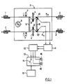
- the object is achieved according to the invention in that the warp threads of each of the two warp thread groups to be linked are guided in the area between the compartment member and a clamp via a thread guide, around which the edge warp thread is deflected when it is moved out of the warp thread plane, in that one of these is in the area of the thread guide assigned measuring element for measuring the force acting through a deflected warp thread on the deflection point or on the compartment element, and that the measurement signal obtained thereby forms the criterion for the presence of a double thread.
- the thread groups K a and K n are guided through the knitting area of a knotting machine 3.
- the knotting machine 3 is attached to one of the two side edges of the thread coulters K a and K n and then moved transversely to these, whereby a thread of the old and the new weaving chain K a and K n are always linked to one another.
- the knotting process essentially proceeds in such a way that a dividing member 4, 4 'for the two sets of threads K a , K n divides the respective edge warp thread from the thread set and presents a feeder 5, 5', which feeds the thread to a knitting organ 6.
- Each of the two threads is gripped by a thread clamp (not shown) and then the thread ends are cut off by scissors 7, 7 ', which are arranged between the feeders 5, 5' and the knotting organ 6.
- a thread guide 8 and 9 is arranged on each side of the compartment members 4, 4 ', on which the threads of the two sets of threads K a and K n rest.
- the mutual distance between these thread guides is relatively small and is only a few millimeters.
- the threads between the thread guides 8 and 9 assume the position shown in dashed lines and the compartment members 4, 4 'are located above the upper thread family K a and below the lower thread family K n with their ends facing the thread families.
- the sensors 10, 10 'could just as well be arranged on the thread guide 9 facing the knotting organ 6, or they could even each be arranged on one of the two thread guides 8, 9. Likewise, the sensors 10, 10 'could be arranged on the compartment members 4, 4', for example at their bearing points.
- the compartment member 4 in the direction of arrow A downwards when the compartment member 4 in the direction of arrow A downwards is moved, it divides the edge warp thread K r and deflects it out of the plane of the thread family K a . Subsequently, the compartment organ 4 is moved to the right in the direction of arrow B and pulls the divided edge warp thread K r away from the thread family K a via the swivel part 18 on which it slides. So that the warp threads cannot slip into the gap between the rigid part 17 and the swivel part 18, lateral guides (not shown) are arranged in its area.
- Another variant of the measurement of the contact force of the edge warp thread consists in using a piezoelectric transducer for this measurement instead of a strain gauge.
- a suitable deflecting element for the edge warp thread slightly above its support surface is arranged laterally next to the thread guide 8.
- Such a deflecting element can, for example, be bow-shaped or flat and of one be supported on the piezoelectric transducer contacting carrier axis.
- the separated edge warp thread is pushed on its deflection element when it moves away from its thread array and the contact force causes a force in the longitudinal direction of the carrier axis on the piezoelectric transducer.
Landscapes
- Engineering & Computer Science (AREA)
- Textile Engineering (AREA)
- Looms (AREA)
- Auxiliary Weaving Apparatuses, Weavers' Tools, And Shuttles (AREA)
- Yarns And Mechanical Finishing Of Yarns Or Ropes (AREA)
- Filamentary Materials, Packages, And Safety Devices Therefor (AREA)
- Spinning Or Twisting Of Yarns (AREA)
- Preliminary Treatment Of Fibers (AREA)
- Knitting Machines (AREA)
- Warping, Beaming, Or Leasing (AREA)
Claims (12)
- Dispositif de surveillance pour fils doubles sur des machines noueuses de chaîne de tissage, lesquelles comportent un organe de nouage, des pinces pour les nappes de fils de chaîne à nouer entre elles ainsi qu'un organe pour la séparation du fil de chaîne de lisière respectif et pour son déplacement hors du plan des fils de chaîne, caractérisé en ce que les fils de chaîne des deux nappes de fils de chaîne (Ka, Kn) à nouer passent dans la zone entre l'organe séparateur (4, 4') et une pince (2, 2') sur un guidage de fil (8) autour duquel le fil de chaîne de lisière (Kr) est dévié lors du mouvement hors du plan des fils de chaîne, en ce qu'au voisinage du guidage de fil (8) est disposé un organe de mesure (10, 10') associé à celui-ci pour la mesure de la force agissant par un fil de chaîne dévié sur l'emplacement de déviation ou sur l'organe séparateur et en ce que le signal de mesure ainsi obtenu constitue le critère pour la présence d'un fil double.
- Dispositif de surveillance selon la revendication 1, caractérisé en ce que le guidage de fil (8) comporte, dans la zone à côté de la nappe de fils de chaîne (Ka, Kn) , un élément déplaçable ou déformable par un fil de chaîne de lisière (Kr) dévié, par-dessus lequel le fil de chaîne de lisière séparé est déplacé et en ce que l'organe de mesure (10, 10') est monté au voisinage de cet élément.
- Dispositif de surveillance selon la revendication 2, caractérisé en ce que le guidage de fil (8) se compose d'un élément rigide (17) et d'un élément pivotant (18) monté sur celui-ci, lequel forme l'élément déplaçable ou déformable cité et en ce que l'organe de mesure (10, 10') est réalisé pour la détection du déplacement de cet élément pivotant par un fil de chaîne de lisière (Kr) séparé.
- Dispositif de surveillance selon la revendication 3, caractérisé en ce que l'élément pivotant (18) est monté unilatéralement par un ressort à lame (19) sur l'élément rigide (17) et en ce que l'organe de mesure (10, 10') est constitué par deux jauges de contrainte extensométriques fixées à des faces mutuellement opposées de ce ressort à lame ou par un détecteur piézo-électrique sensible à la flexion.
- Dispositif de surveillance selon la revendication 2, caractérisé en ce que le guidage de fil (8) est réalisé, au voisinage de l'élément déplaçable ou déformable, de façon à être flexible par un fil de chaîne de lisière (Kr) séparé et en ce que l'organe de mesure (10, 10') est constitué par une jauge de contrainte extensométrique (20) encastrée entre l'élément flexible et l'élément rigide (17) du guidage de fil ou par un détecteur piézo-électrique sensible à la flexion.
- Dispositif de surveillance selon la revendication 5, caractérisé en ce que la jauge de contrainte extensométrique (20') est appliquée sur un support (23) en matière synthétique élastique.
- Dispositif de surveillance selon la revendication 6, caractérisé en ce que la jauge de contrainte extensométrique (20') est noyée, de préférence incorporée par coulée dans un support (23) en matière synthétique élastique.
- Dispositif de surveillance selon la revendication 2, caractérisé en ce que le guidage de fil (8) comporte , au voisinage de l'élément déplaçable ou déformable, un élément relié à un transformateur piézo-électrique et dont la force sur le transformateur est proportionnelle à la force d'appui d'un fil de chaîne de lisière (Kr) séparé.
- Dispositif de surveillance selon la revendication 8, caractérisé en ce que l'élément cité est réalisé en forme d'étrier ou de façon plane et porté par un axe orienté en direction de la force d'appui et en contact avec le convertisseur piézo-électrique.
- Dispositif de surveillance selon l'une des revendications 1 à 9, caractérisé en ce que le signal de mesure de chaque organe de mesure (10, 10') est amené, par l'intermédiaire d'un amplificateur (11) et d'un étage d'interprétation (12), à l'unité de commande (13) de la machine noueuse (3).
- Dispositif de surveillance selon la revendication 10, caractérisé en ce que l'étage d'interprétation (12) comporte un détecteur de valeur de seuil pour les signaux de mesure, dont la valeur de seuil est réglée de telle façon qu'un signal de mesure, excédant celle-ci, indique la séparation d'un fil double.
- Dispositif de surveillance selon la revendication 11 , caractérisé en ce que l'unité de commande (13) de la machine noueuse (3) comporte un interrupteur (14) établissant ou interrompant la liaison avec son moteur d'entraînement (15) ainsi que des indicateurs séparés (16, 16') pour l'apparition d'un fil double dans l'une des deux nappes de fils de chaîne (Ka, Kn) et en ce que l'interrupteur et les indicateurs sont pilotés par le signal de sortie de l'étage d'interprétation (12).
Priority Applications (1)
| Application Number | Priority Date | Filing Date | Title |
|---|---|---|---|
| AT86108183T ATE66501T1 (de) | 1985-06-26 | 1986-06-16 | Ueberwachungsvorrichtung fuer doppelfaeden an webkettenknuepfmaschinen. |
Applications Claiming Priority (2)
| Application Number | Priority Date | Filing Date | Title |
|---|---|---|---|
| CH2716/85 | 1985-06-26 | ||
| CH2716/85A CH668277A5 (de) | 1985-06-26 | 1985-06-26 | Ueberwachungsvorrichtung fuer doppelfaeden an webkettenknuepfmaschinen. |
Publications (3)
| Publication Number | Publication Date |
|---|---|
| EP0206196A2 EP0206196A2 (fr) | 1986-12-30 |
| EP0206196A3 EP0206196A3 (en) | 1989-04-05 |
| EP0206196B1 true EP0206196B1 (fr) | 1991-08-21 |
Family
ID=4239988
Family Applications (1)
| Application Number | Title | Priority Date | Filing Date |
|---|---|---|---|
| EP86108183A Expired - Lifetime EP0206196B1 (fr) | 1985-06-26 | 1986-06-16 | Dispositif de contrôle pour les fils doubles dans les noueuses de chaîne |
Country Status (6)
| Country | Link |
|---|---|
| US (1) | US4805276A (fr) |
| EP (1) | EP0206196B1 (fr) |
| JP (1) | JPH0718077B2 (fr) |
| AT (1) | ATE66501T1 (fr) |
| CH (1) | CH668277A5 (fr) |
| DE (1) | DE3680957D1 (fr) |
Families Citing this family (11)
| Publication number | Priority date | Publication date | Assignee | Title |
|---|---|---|---|---|
| BE1000900A4 (nl) * | 1987-09-02 | 1989-05-09 | Picanol Nv | Meet-en detektie-inrichting voor het bepalen van de plaats van een breuk in een kettingdraad bij weefmachines. |
| JPH07101795B2 (ja) * | 1990-03-26 | 1995-11-01 | 日本たばこ産業株式会社 | ワーク搬送方法 |
| KR930004078B1 (ko) * | 1990-03-28 | 1993-05-20 | 쯔다고마 고오교오 가부시끼가이샤 | 수복(修腹)후의 경사의 처리방법 |
| CH687540A5 (de) * | 1992-02-07 | 1996-12-31 | Staeubli Ag | Verfahren und Vorrichtung zur Bestimmung von Festigkeitseigenschaften der Kettfaeden einer Webkette. |
| CH685635A5 (de) * | 1992-06-17 | 1995-08-31 | Zellweger Uster Ag | Anordnung zur Kontrolle des Vorhandenseins von Fäden einer aufgespannten Fadenschicht an einer Textilmaschine. |
| EP1870501A1 (fr) * | 2006-06-23 | 2007-12-26 | Stäubli AG Pfäffikon | Dispositif de séparation de fils d'une couche de fils, procédé pour opérer le dit dispositif et utilisation du dit dispositif |
| EP1908866A1 (fr) * | 2006-10-06 | 2008-04-09 | Stäubli AG Pfäffikon | Dispositif et procédé pour lier des fils d'une première couche des fils avec des fils d'une deuxième couche des fils |
| CN104114473B (zh) * | 2012-01-24 | 2017-03-15 | 耐克创新有限合伙公司 | 间歇编织接合器 |
| CN104126041B (zh) | 2012-01-24 | 2017-10-10 | 耐克创新有限合伙公司 | 多层编织 |
| CN106995971A (zh) * | 2017-04-22 | 2017-08-01 | 诸暨市凯利纺织机械有限公司 | 具有规则分线功能的结经机 |
| CN112357687A (zh) * | 2020-09-22 | 2021-02-12 | 夏西明 | 一种接经机的自动控制系统 |
Family Cites Families (17)
| Publication number | Priority date | Publication date | Assignee | Title |
|---|---|---|---|---|
| US2369536A (en) * | 1943-11-13 | 1945-02-13 | Barber Colman Co | Warp tying machine |
| DE875029C (de) * | 1950-07-06 | 1953-04-30 | Guido Herrmann Maschf | Einrichtung zum UEberfuehren der zu vereinigenden Faeden von der Abteilvorrichtung zu den Knuepfwerkzeugen bei Fadenanknuepfmaschinen, z. B. Webkettenanknuepfmaschinen |
| CH348937A (de) * | 1956-07-10 | 1960-09-15 | Zellweger Uster Ag | Vorrichtung zum Abteilen von kreuzeingelesenen Kettfäden |
| DE1118109B (de) * | 1957-04-18 | 1961-11-23 | Knotex Maschb G M B H | Webkettenknuepfmaschine |
| US2928159A (en) * | 1958-01-18 | 1960-03-15 | Zellweger Uster Ag | Machine for separating the outside thread of a warp |
| DE1560548B2 (de) * | 1963-09-21 | 1977-01-20 | Reiners, Walter, Dr.-Ing., 4050 Mönchengladbach | Spulmaschine mit automatischer knotvorrichtung und einer ueberwachungsvorrichtung fuer die knotung von doppelfaeden |
| US3280623A (en) * | 1964-04-10 | 1966-10-25 | Erwin J Saxl | Load cell for measurement of low forces |
| CH415488A (de) * | 1964-05-08 | 1966-06-15 | Zellweger Uster Ag | Vorrichtung zur Auslösung einer Abstellvorrichtung an einer Webkettenvorbereitungsmaschine beim Versagen eines Fadenabtrennorgans |
| US3526130A (en) * | 1968-04-08 | 1970-09-01 | Owens Corning Fiberglass Corp | Apparatus and method for measuring tension in linear material |
| BE787621A (fr) * | 1971-08-16 | 1973-02-16 | Sandoz Sa | Procede de preparation de composes disazoiques reactifs utilisables notamment pour la teinture de fibres cellulosiques |
| US3840951A (en) * | 1971-08-23 | 1974-10-15 | Barber Colman Co | Double thread detector |
| US3765777A (en) * | 1972-02-22 | 1973-10-16 | Monsanto Co | Device for locating and identifying threadline defects |
| SU506656A1 (ru) * | 1973-12-24 | 1976-03-15 | Коломенский Завод Текстильного Машиностроения | Механизм отбора нитей основы к узлов зальной машине |
| CH619011A5 (fr) * | 1977-06-24 | 1980-08-29 | Zellweger Uster Ag | |
| US4233837A (en) * | 1979-02-08 | 1980-11-18 | Owens-Corning Fiberglas Corporation | Apparatus for measuring tension in a linear material |
| EP0023583B1 (fr) * | 1979-08-03 | 1982-11-17 | Akzo GmbH | Procédé et dispositif pour constater les différences de tension de fil |
| GB2080552B (en) * | 1980-07-12 | 1984-11-21 | Rubery Owen Group Services Ltd | Measuring loads |
-
1985
- 1985-06-26 CH CH2716/85A patent/CH668277A5/de not_active IP Right Cessation
-
1986
- 1986-06-16 DE DE8686108183T patent/DE3680957D1/de not_active Expired - Lifetime
- 1986-06-16 AT AT86108183T patent/ATE66501T1/de not_active IP Right Cessation
- 1986-06-16 EP EP86108183A patent/EP0206196B1/fr not_active Expired - Lifetime
- 1986-06-24 US US06/878,005 patent/US4805276A/en not_active Expired - Lifetime
- 1986-06-24 JP JP61146322A patent/JPH0718077B2/ja not_active Expired - Fee Related
Also Published As
| Publication number | Publication date |
|---|---|
| CH668277A5 (de) | 1988-12-15 |
| EP0206196A2 (fr) | 1986-12-30 |
| EP0206196A3 (en) | 1989-04-05 |
| DE3680957D1 (de) | 1991-09-26 |
| JPS626945A (ja) | 1987-01-13 |
| ATE66501T1 (de) | 1991-09-15 |
| JPH0718077B2 (ja) | 1995-03-01 |
| US4805276A (en) | 1989-02-21 |
Similar Documents
| Publication | Publication Date | Title |
|---|---|---|
| EP0206196B1 (fr) | Dispositif de contrôle pour les fils doubles dans les noueuses de chaîne | |
| EP0385061B1 (fr) | Dispositif de machine à tisser, pour la mesure de la tension de châine | |
| DE2727211C2 (de) | Schußfadenfühler für Webmaschinen | |
| DE2704045B2 (de) | Vorrichtung zum Verhindern von Doppelabzügen | |
| EP0023583B1 (fr) | Procédé et dispositif pour constater les différences de tension de fil | |
| EP0769581B1 (fr) | Dispositif pour réduire la charge d'un fil de trame devant être inséré dans la foule d'un métier à tisser | |
| DE19501186A1 (de) | Bogenabfühlschuh, Dickenabtastkopf und Dickenmeßsystem | |
| EP0906461B1 (fr) | Pince de transfert pour une machine a tisser a rapieres | |
| DE3833969A1 (de) | Garnzufuhreinrichtung | |
| CH687540A5 (de) | Verfahren und Vorrichtung zur Bestimmung von Festigkeitseigenschaften der Kettfaeden einer Webkette. | |
| EP0816545B1 (fr) | Dispositif de détection d'une insertion de trame défecteueuse sur un métier à tisser à griffes | |
| EP0498203B1 (fr) | Dispositif pour fixer les cordelettes pour machines à broder | |
| DE3003105C2 (fr) | ||
| DE2105559A1 (en) | Weft thread detector - fitted to air jet shuttless looms | |
| DE69911214T2 (de) | Verschlingungsschutz für einen fadenlieferspeicher | |
| EP2837281A1 (fr) | Dispositif de noeuds pour une presse à balles | |
| CH711314A2 (de) | Schiffchenstickmaschine mit Messvorrichtung zur Überwachung der Fadenspannung des Nadelfadens und Verfahren hierzu. | |
| DE2705080C2 (de) | Fadentastvorrichtung für Kreuzspulautomaten | |
| EP0460442A1 (fr) | Dispositif de mesure de l'épaisseur et/ou de l'inégalite de rubans de fibres | |
| DE69717368T2 (de) | Schussfadenbremse insbesondere für Luftdüsenwebmaschinen | |
| CH651812A5 (de) | Vorrichtung zum abziehen von garnenden an textilspulen. | |
| EP0495229B1 (fr) | Détecteur de fil | |
| DE102007053466A1 (de) | Vorrichtung zum Spannen eines längsbewegten Fadens | |
| CH646470A5 (de) | Duesenwebmaschine. | |
| CH677480A5 (en) | Counting of printed sheets - using data on edges of sheets accessible by change in feed direction of sheets on conveyor |
Legal Events
| Date | Code | Title | Description |
|---|---|---|---|
| PUAI | Public reference made under article 153(3) epc to a published international application that has entered the european phase |
Free format text: ORIGINAL CODE: 0009012 |
|
| 17P | Request for examination filed |
Effective date: 19860616 |
|
| AK | Designated contracting states |
Kind code of ref document: A2 Designated state(s): AT BE DE FR GB IT LU NL SE |
|
| PUAL | Search report despatched |
Free format text: ORIGINAL CODE: 0009013 |
|
| AK | Designated contracting states |
Kind code of ref document: A3 Designated state(s): AT BE DE FR GB IT LU NL SE |
|
| RHK1 | Main classification (correction) |
Ipc: D03J 1/18 |
|
| 17Q | First examination report despatched |
Effective date: 19900829 |
|
| ITF | It: translation for a ep patent filed | ||
| GRAA | (expected) grant |
Free format text: ORIGINAL CODE: 0009210 |
|
| AK | Designated contracting states |
Kind code of ref document: B1 Designated state(s): AT BE DE FR GB IT LU NL SE |
|
| REF | Corresponds to: |
Ref document number: 66501 Country of ref document: AT Date of ref document: 19910915 Kind code of ref document: T |
|
| REF | Corresponds to: |
Ref document number: 3680957 Country of ref document: DE Date of ref document: 19910926 |
|
| GBT | Gb: translation of ep patent filed (gb section 77(6)(a)/1977) | ||
| ET | Fr: translation filed | ||
| PLBE | No opposition filed within time limit |
Free format text: ORIGINAL CODE: 0009261 |
|
| STAA | Information on the status of an ep patent application or granted ep patent |
Free format text: STATUS: NO OPPOSITION FILED WITHIN TIME LIMIT |
|
| 26N | No opposition filed | ||
| EPTA | Lu: last paid annual fee | ||
| EAL | Se: european patent in force in sweden |
Ref document number: 86108183.4 |
|
| PGFP | Annual fee paid to national office [announced via postgrant information from national office to epo] |
Ref country code: LU Payment date: 19950701 Year of fee payment: 10 |
|
| PG25 | Lapsed in a contracting state [announced via postgrant information from national office to epo] |
Ref country code: LU Free format text: LAPSE BECAUSE OF NON-PAYMENT OF DUE FEES Effective date: 19960616 |
|
| PGFP | Annual fee paid to national office [announced via postgrant information from national office to epo] |
Ref country code: GB Payment date: 19981127 Year of fee payment: 13 |
|
| PG25 | Lapsed in a contracting state [announced via postgrant information from national office to epo] |
Ref country code: GB Free format text: LAPSE BECAUSE OF NON-PAYMENT OF DUE FEES Effective date: 19990616 |
|
| PGFP | Annual fee paid to national office [announced via postgrant information from national office to epo] |
Ref country code: SE Payment date: 19991124 Year of fee payment: 14 |
|
| PGFP | Annual fee paid to national office [announced via postgrant information from national office to epo] |
Ref country code: AT Payment date: 19991125 Year of fee payment: 14 |
|
| PGFP | Annual fee paid to national office [announced via postgrant information from national office to epo] |
Ref country code: NL Payment date: 19991130 Year of fee payment: 14 |
|
| GBPC | Gb: european patent ceased through non-payment of renewal fee |
Effective date: 19990616 |
|
| PG25 | Lapsed in a contracting state [announced via postgrant information from national office to epo] |
Ref country code: AT Free format text: LAPSE BECAUSE OF NON-PAYMENT OF DUE FEES Effective date: 20000616 |
|
| PG25 | Lapsed in a contracting state [announced via postgrant information from national office to epo] |
Ref country code: SE Free format text: LAPSE BECAUSE OF NON-PAYMENT OF DUE FEES Effective date: 20000617 |
|
| PG25 | Lapsed in a contracting state [announced via postgrant information from national office to epo] |
Ref country code: NL Free format text: LAPSE BECAUSE OF NON-PAYMENT OF DUE FEES Effective date: 20010101 |
|
| EUG | Se: european patent has lapsed |
Ref document number: 86108183.4 |
|
| NLV4 | Nl: lapsed or anulled due to non-payment of the annual fee |
Effective date: 20010101 |
|
| PGFP | Annual fee paid to national office [announced via postgrant information from national office to epo] |
Ref country code: FR Payment date: 20050610 Year of fee payment: 20 |
|
| PGFP | Annual fee paid to national office [announced via postgrant information from national office to epo] |
Ref country code: DE Payment date: 20050613 Year of fee payment: 20 |
|
| PGFP | Annual fee paid to national office [announced via postgrant information from national office to epo] |
Ref country code: IT Payment date: 20050621 Year of fee payment: 20 |
|
| PGFP | Annual fee paid to national office [announced via postgrant information from national office to epo] |
Ref country code: BE Payment date: 20050704 Year of fee payment: 20 |
|
| BE20 | Be: patent expired |
Owner name: *ZELLWEGER USTER A.G. Effective date: 20060616 |